[Transcriber’s note: Image sizes are limited to the browser
window size. To expand an image, right click on the image and
select “view image” or “open image in new tab”. Then click
on the new image to see it full size. You could also just
use you favorite image viewer directly.
Many projects are of contemporary interest—magic, kites and
boomerangs for example. Try a
“Querl” for starters.
There are many projects of purely historical interest, such as
chemical photography, phonographs, and devices for coal
furnaces.
Another class of projects illustrate the caviler attitude toward
environment and health in 1913. These projects involve items
such as
asbestos, gunpowder, acetylene, hydrogen, lead, mercury, sulfuric
acid, nitric acid, cadmium, potassium sulfate, potassium cyanide,
potassium ferrocyanide, copper sulfate, and hydrochloric acid.
Many references to these have been highlighted in red.
Projects requiring extra skill and care that involve
high voltage, melting metals, or other hazards, have the title
highlighted.
Please view these as snapshots of culture and attitude, not as
suggestions for contemporary activity.
Be careful and have fun, or simply read and enjoy a trip into
yesterday.]
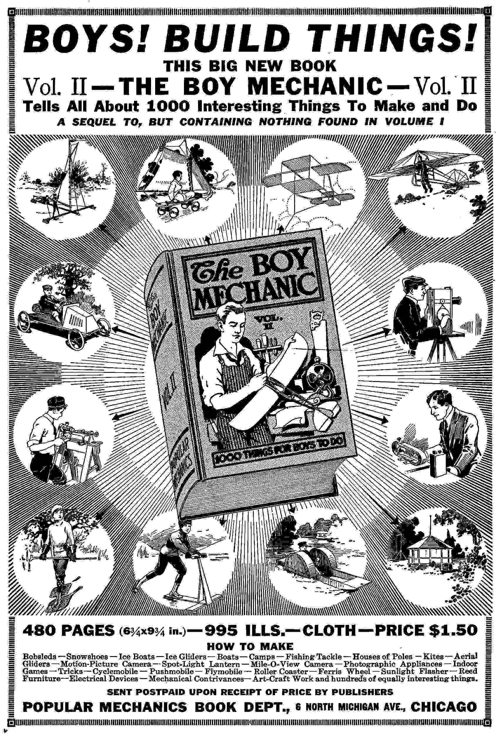
The Boy Mechanic
Vol. 1
700 Things for Boys to Do
800 Illustrations Showing How
The Boy Mechanic
Vol. 1
Index
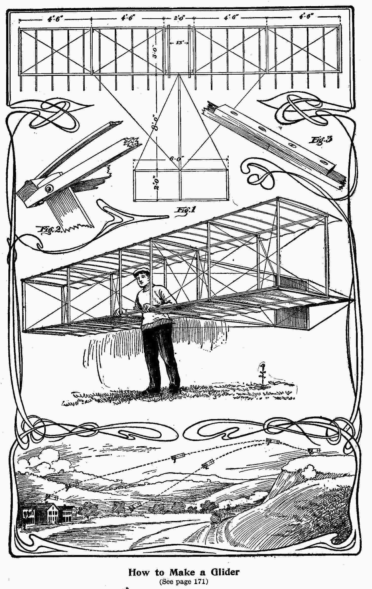
How to Make a Glider
(See page 171)
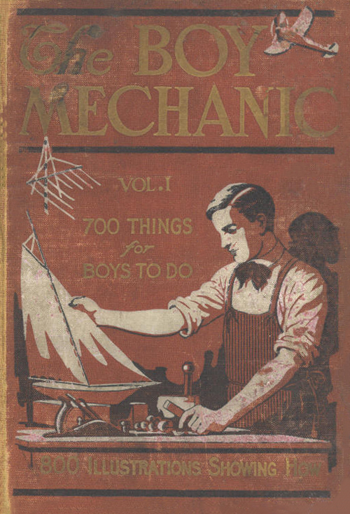
The Boy Mechanic
Volume I
700 Things For Boys To Do
How To Construct
Wireless Outfits, Boats, Camp Equipment,
Aerial Gliders, Kites,
Self-propelled Vehicles Engines, Motors,
Electrical Apparatus, Cameras
And
Hundreds Of Other Things Which Delight Every Boy
With 800 Illustrations
Copyrighted, 1913, By H. H. Windsor
Chicago
Popular Mechanics Co.
Publishers
A Model Steam Engine
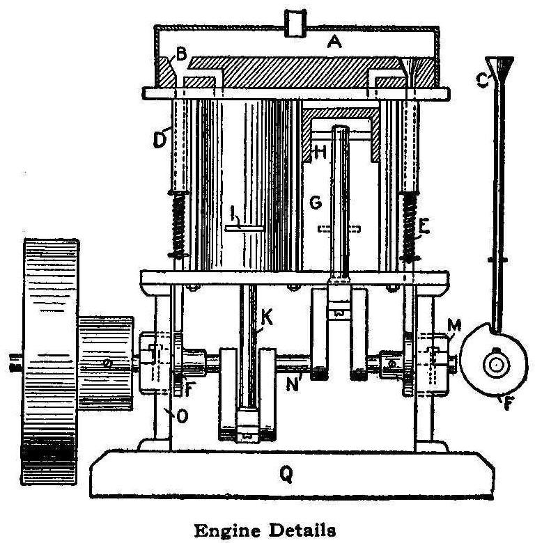
Engine Details
The accompanying sketch illustrates a two-cylinder single-acting,
poppet valve steam engine of home construction.
The entire engine, excepting the flywheel, shaft, valve cams,
pistons and bracing rods connecting the upper and lower plates of
the frame proper, is of brass, the other parts named being of
cast iron and bar steel.
The cylinders, G, are of seamless brass tubing, 1-1/2 in. outside
diameter; the pistons, H, are ordinary 1-1/2 in. pipe caps turned
to a plug fit, and ground into the cylinders with oil and emery.
This operation also finishes the inside of the cylinders.
The upright rods binding the top and bottom plates are of steel
rod about 1/8-in. in diameter, threaded into the top plate and
passing through holes in the bottom plate with hexagonal brass
nuts beneath.
The valves, C, and their seats, B, bored with a countersink bit,
are plainly shown. The valves were made by threading a copper
washer, 3/8 in. in diameter, and screwing it on the end of the
valve rod, then wiping on roughly a tapered mass of solder and
grinding it into the seats B with emery and oil.
The valve rods operate in guides, D, made of 1/4-in. brass
tubing, which passes through the top plate and into the heavy
brass bar containing the valve seats and steam passages at the
top, into which they are plug-fitted and soldered.
The
location and arrangement of the valve seats and steam passages
are shown in the sketch, the flat bar containing them being
soldered to the top plate.
The steam chest, A, over the valve mechanism is constructed of
1-in. square brass tubing, one side being sawed out and the open
ends fitted with pieces of 1/16 in. sheet brass and soldered in.
The steam inlet is a gasoline pipe connection such as used on
automobiles.
The valve-operating cams,
F, are made of the metal ends of an old typewriter platen, one
being finished to shape and then firmly fastened face to face to
the other, and used as a pattern in filing the other to shape.
Attachment to the shaft, N, is by means of setscrews which pass
through the sleeves.
The main bearings, M, on the supports, O, and the crank-end
bearings of the connecting rods, K, are split and held in
position by machine screws with provision for taking them up when
worn.
The exhausting of spent steam is accomplished by means of slots,
I, sawed into the fronts of the cylinders at about 1/8 in. above
the lowest position of the piston’s top at the end of the stroke,
at which position of the piston the valve rod drops into the
cutout portion of the cam and allows the valve to seat.
All the work on this engine, save turning the pistons, which was
done in a machine shop for a small sum, and making the flywheel,
this being taken from an old dismantled model, was accomplished
with a hacksaw, bench drill, carborundum wheel, files, taps and
dies. The base, Q, is made of a heavy piece of brass.
The action is smooth and the speed high. Steam is supplied by a
sheet brass boiler of about 3 pt. capacity, heated with a Bunsen
burner.
Contributed by Harry F. Lowe, Washington, D. C.
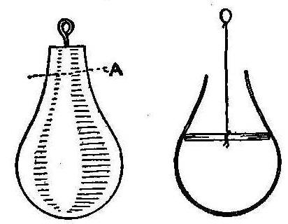
Magic Spirit Hand
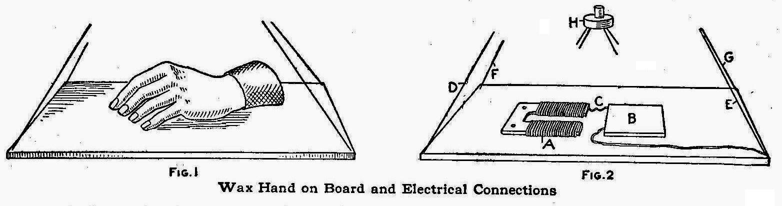
Wax Hand on Board and Electrical Connections
The magic hand made of wax is given to the audience for
examination, also a board which is suspended by four pieces of
common picture-frame wire. The hand is placed upon the board and
answers, by rapping, any question asked by members of the
audience. The hand and the board may be examined at any time and
yet the rapping can be continued, though surrounded by the
audience.
The Magic Wand, London, gives the secret of this spirit hand as
follows: The hand is prepared by concealing in the wrist a few
soft iron plates, the wrist being afterwards bound with black
velvet as shown in Fig. 1. The board is hollow, the top being
made of thin veneer (Fig. 2). A small magnet, A, is connected to
a small flat pocket lamp battery, B. The board is suspended by
four lengths of picture-frame wire one of which, E, is connected
to the battery and another, D, to the magnet. The other wires, F
and G, are only holding wires. All the wires are fastened to a
small ornamental switch, H, which is fitted with a connecting
plug at the top. The plug can be taken out or put in as desired.
The top of the board must be made to open or slide off so that
when the battery is exhausted a new one can be installed.
Everything must be firmly fixed to the board and the hollow space
filled in with wax, which will make the board sound solid when
tapped.
In presenting the trick, the performer gives the hand and board
with wires and switch for examination, keeping the plug concealed
in his right hand. When receiving the board back, the plug is
secretly pushed into the switch, which is held in the right hand.
The hand is then placed on the board over the magnet. When the
performer wishes the hand to move he pushes the plug in, which
turns on the current and causes the magnet to attract the iron in
the wrist, and will, therefore, make the hand rap. The switch can
be made similar to an ordinary push button so the rapping may be
easily controlled without detection by the audience.
Making Skis and Toboggans
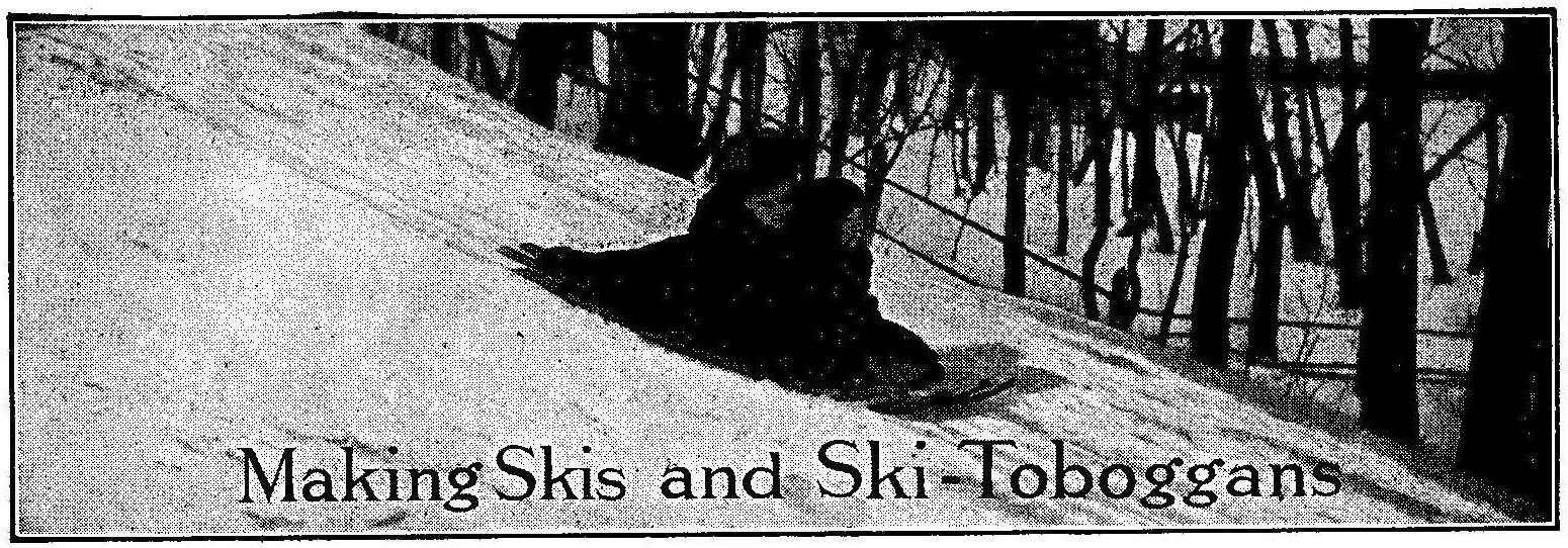
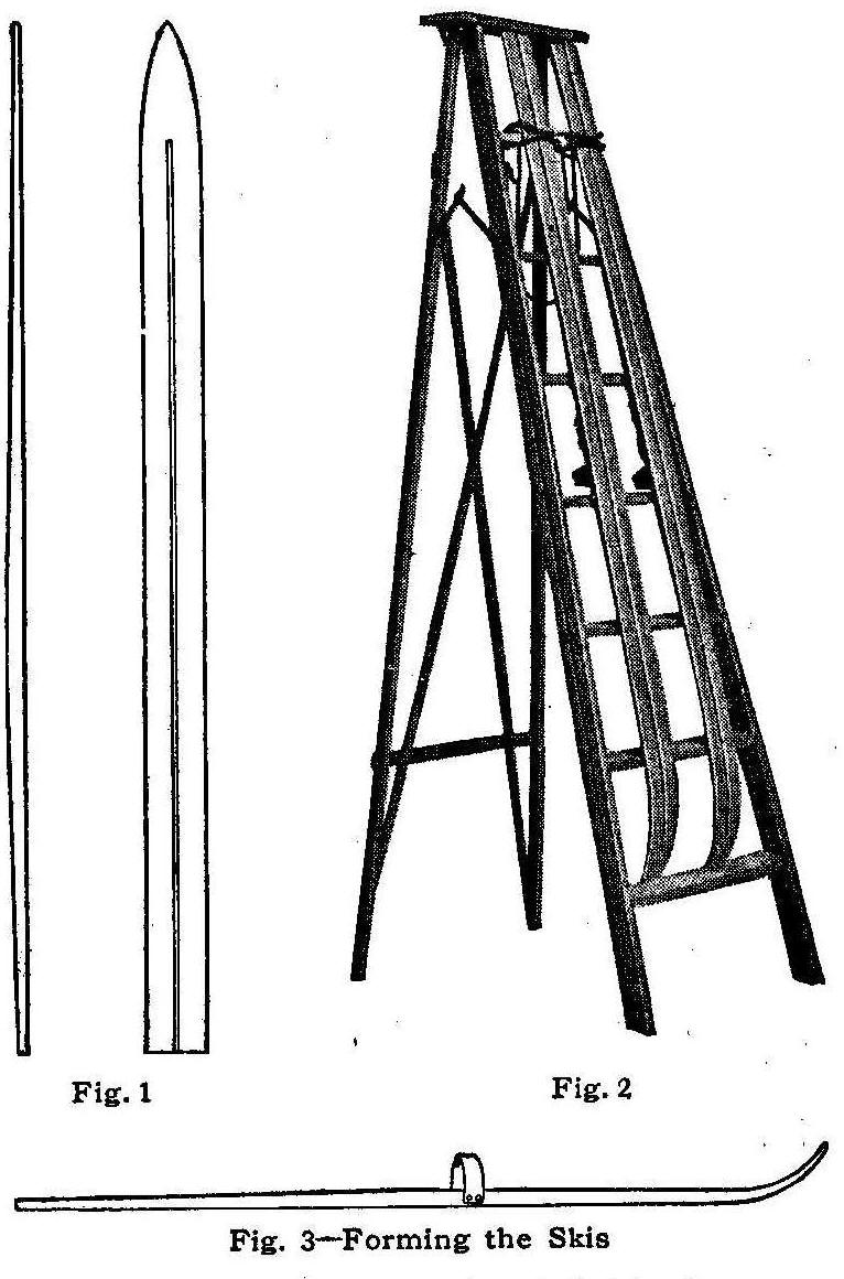
Fig.1, 2, 3—Forming the skis
During the winter months everyone is thinking of skating,
coasting or ski running and jumping. Those too timid to run down
a hill standing upright on skis must take their pleasure in
coasting or skating.
The ordinary ski can be made into a coasting ski-toboggan by
joining two pairs together with bars without injury to their use
for running and jumping. The ordinary factory-made skis cost from
$2.50 per pair up, but any boy can make an excellent pair for 50
cents.
In making a pair of skis, select two strips of Norway pine free
from knots, 1 in. thick, 4 in. wide and 7 or 8 ft. long. Try to
procure as fine and straight a grain as possible. The pieces are
dressed thin at both ends leaving about 1 ft. in the center the
full thickness of 1 in., and gradually thinning to a scant 1/2
in. at the ends. One end of each piece is tapered to a point
beginning 12 in. from the end. A groove is cut on the under side,
about 1/4 in. wide and 1/8 in. deep, and running almost the full
length of the ski. This will make it track straight and tends to
prevent side slipping. The shape of each piece for a ski, as it
appears before bending, is shown in Fig. 1.
The pointed end of each piece is placed in boiling water for at
least 1 hour, after which the pieces are ready for bending. The
bend is made on an ordinary stepladder. The pointed ends are
stuck under the back of one step and the other end securely tied
to the ladder, as shown in Fig. 2. They should remain tied to the
ladder 48 hours in a moderate temperature, after which they will
hold their shape permanently.
The two straps, Fig. 3, are nailed an a little forward of the
center of gravity so that when the foot is lifted, the front of
the ski will be raised. Tack on a piece of sheepskin or deer hide
where the foot rests, Fig. 4.
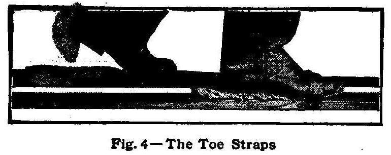
Fig. 4—The Toe Straps
The best finish for skis is boiled linseed oil. After two or
three applications the under side will take a polish like glass
from the contact with the snow.
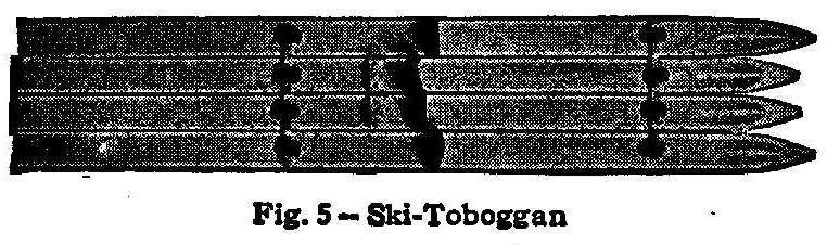
Fig. 5—Ski-Toboggan
The ski-toboggan is made by placing two pairs of skis together
side by side and fastening them with two bars across the top. The
bars are held with V-shaped metal clips as shown in Fig. 5.
Contributed by Frank Scobie, Sleepy Eye, Minn.
Homemade Life Preserver
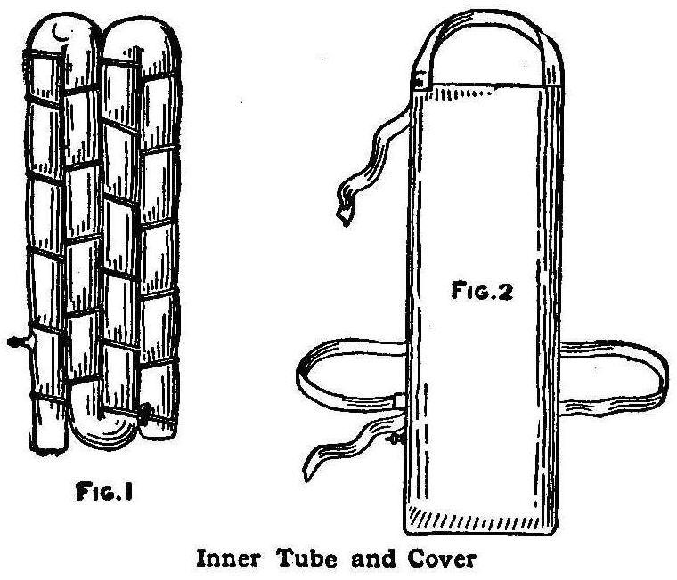
Fig. 1, Fig. 2—Inner Tube and Cover
Procure an inner tube of a bicycle tire, the closed-end kind, and
fold it in four alternate sections, as shown in Fig. 1. Cut or
tear a piece of cloth into strips about 1/2 in. wide, and knot
them together. Fasten this long strip of cloth to the folded tube
and weave it alternately in and out, having each run of the cloth
about 4 in. apart, until it is bound as shown in Fig. 1. Make a
case of canvas that will snugly fit the folded tube when
inflated. The straps that hold the preserver to the body may be
made of old suspender straps. They are sewed to the case at one
end and fastened at the other with clasps such as used on overall
straps. The tube can be easily inflated by blowing into the
valve, at the same time holding the valve stem down with the
teeth. The finished preserver is shown in Fig. 2.
How to Make Boomerangs
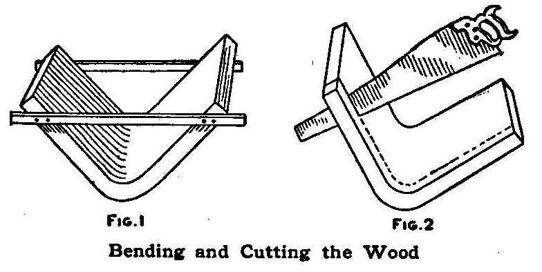
Bending and Cutting the Wood
When the ice is too thin for skating and the snow is not right
for skis, about the only thing to do is to stay in the house. A
boomerang club will help to fill in between and also furnishes
good exercise for the muscles of the arm. A boomerang can be made
of a piece of well seasoned hickory plank. The plank is well
steamed in a wash boiler or other large kettle and then bent to a
nice curve, as shown in Fig. 1. It is held in this curve until
dry, with two pieces nailed on the sides as shown.
After the piece is thoroughly dried out, remove the side pieces
and cut it into sections with a saw, as shown in Fig. 2. The
pieces are then dressed round. A piece of plank 12 in. wide and 2
ft. long will make six boomerangs. To throw a boomerang, grasp it
and hold the same as a club, with the hollow side away from you.
Practice first at some object about 25 ft. distant, and in a
short time the thrower will be able to hit the mark over 100 ft.
away. Any worker in wood can turn out a great number of
boomerangs cheaply.
Contributed by J. E. Noble, Toronto, Ontario.
How to Make an Eskimo Snow House
By George E. Walsh
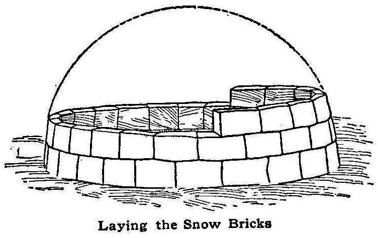
Laying the Snow Bricks
Playing in the snow can be raised to a fine art if boys and girls
will build their creations with some attempt at architectural
skill and not content themselves with mere rough work. Working in
snow and ice opens a wide field for an expression of taste and
invention, but the construction of houses and forts out of this
plastic material provides the greatest amount of pleasure to the
normally healthy boy or girl.
The snow house of the Eskimo is probably the unhealthiest of
buildings made by any savage to live in, but it makes an
excellent playhouse in winter, and represents at the same time a
most ingenious employment of the arch system in building. The
Eskimos build their snow houses without the aid of any
scaffolding or interior false work, and while there is a keystone
at the top of the dome, it is not essential to the support of the
walls. These are self-supporting from the time the first snow
blocks are put down until the last course is laid.
The snow house is of the beehive shape and the ground plan is
that of a circle. The circle is first laid out on the ground and
a space cleared for it. Then a row of snow blocks is laid on the
ground and another course of similar blocks placed on top. The
snow blocks are not exactly square in shape, but about 12 in.
long, 6 in. high and 4 or 5 in. thick. Larger or smaller blocks
can be used, according to size of the house and thickness of the
walls.
First, the snow blocks must be packed and pressed firmly into
position out of moist snow that will pack. A very light, dry snow
will not pack easily, and it may be necessary to use a little
water. If the snow is of the right consistency, there will be no
trouble in packing and working with it. As most of the blocks are
to be of the same size throughout, it will pay to make a mold for
them by forming a box of old boards nailed together, minus the
top, and with a movable bottom, or rather no bottom at all. Place
the four sided box on a flat board and ram snow in it, forcing it
down closely. Then by lifting the box up and tapping the box from
above, the block will drop out. In this way blocks of uniform
size are formed, which makes the building simpler and easier.
While one boy makes the blocks another can shave them off at the
edges and two others can build the house, one inside of the
circle and the other outside. The Eskimos build their snow houses
in this way, and the man inside stays there until he is
completely walled in. Then the door and a window are cut through
the wall.
Each layer of snow blocks must have a slight slant at the top
toward the center so that the walls will constantly curve inward.
This slant at the top is obtained better by slicing off the lower
surfaces of each block before putting it in its course. The top
will then have a uniform inward slant.
The first course of the snow house should be thicker than the
others, and the thickness of the walls gradually decreases toward
the top. A wall, however, made of 6-in. blocks throughout will
hold up a snow house perfectly, if its top is no more than 6 or 7
ft. above the ground. If a higher house is needed the walls
should be thicker at the base and well up toward the middle.
The builder has no mortar for binding the blocks together, and
therefore he must make his joints smooth and even and force in
loose snow to fill up the crevices. A little experience will
enable one to do this work well, and the construction of the
house will proceed rapidly. The Eskimos build additions to their
houses by adding various dome-shaped structures to one side, and
the young architect can imitate them. Such dome-shaped
structures are shown in one of the illustrations.
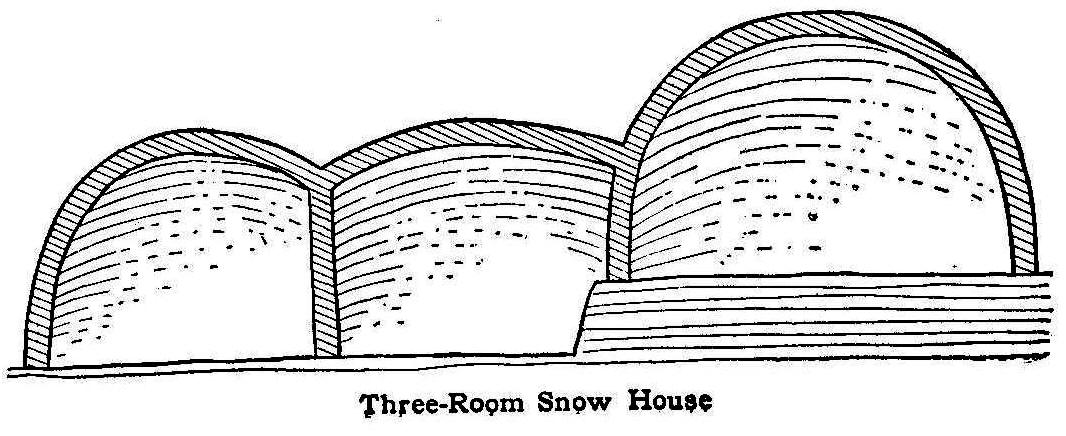
Three-Room Snow House
A fact not well understood and appreciated is that the Eskimo
beehive snow house represents true arch building. It requires no
scaffolding in building and it exerts no outward thrust. In the
ordinary keystone arch used by builders, a, temporary structure
must be erected to hold the walls up until the keystone is fitted
in position, and the base must be buttressed against an outward
thrust. The Eskimo does not have to consider these points. There
is no outward thrust, and the top keystone is not necessary to
hold the structure up. It is doubtful whether such an arch could
be built of brick or stone without scaffolding, but with the snow
blocks it is a simple matter.
Secret Door Lock
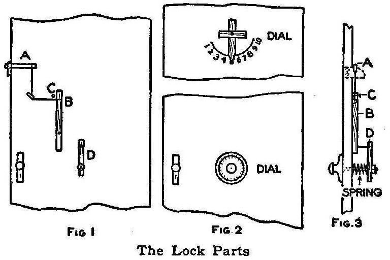
Fig. 1, Fig. 2, Fig. 3—The Lock Parts
The sketch shows the construction of a lock I have on a door
which is quite a mystery to those who do not know how it
operates. It also keeps them out. The parts of the lock on the
inside of the door are shown in Fig. 1. These parts can be
covered so that no one can see them.
The ordinary latch and catch A are attached to the door in the
usual manner. The latch is lifted with a stick of wood B, which
is about 1 ft. long and 1 in. wide, and pivoted about two-thirds
of the way from the top as shown. The latch A is connected to the
stick B with a strong cord run through a staple to secure a
right-angle pull between the pieces. A nail, C, keeps the stick B
from falling over to the left. The piece of wood, D, is 6 or 8
in. long and attached to a bolt that runs through the door, the
opposite end being fastened to the combination dial. Two kinds of
dials are shown in Fig. 2. The piece D is fastened on the bolt an
inch or two from the surface of the door to permit placing a
spiral spring of medium strength in between as shown in Fig. 3.
The opposite end of the bolt may be screwed into the dial, which
can be made of wood, or an old safe dial will do. A nail is
driven through the outer end of the piece D and the end cut off
so that it will pass over the piece B when the dial is turned.
When the dial is pulled out slightly and then turned toward the
right, the nail will catch on the piece B and open the latch.
Contributed by Geo. Goodbrod, Union, Ore.
A Convenient Hot-Dish Holder
Holders in a Convenient Place
When taking hot dishes from the stove, it is very convenient to
have holders handy for use. For this purpose I screwed two screw
eyes into the ceiling, one in front of the stove directly above
the place where the holder should hang, and the other back of the
stove and out of the way. I next ran a strong cord through the
two eyes. To one end of the cord I attached a weight made of a
clean lump of coal. The cord is just long enough to let the
weight hang a few inches above the floor and pass through both
screw eyes. I fastened a small ring to the other end to keep the
cord from slipping back by the pull of the weight. I then
fastened two pieces of string to the ring at the end of the cord
and attached an iron holder to the end of each string. The
strings should be just long enough to keep the holders just over
the stove where they are always ready for use, as the weight
always draws them back to place.
Contributed by R. S. Merrill, Syracuse, New York.
Magic-Box Escape
Box with Hinges and Lock.
The things required to make this trick are a heavy packing box
with cover, one pair of special hinges, one or two hasps for as
many padlocks and a small buttonhook, says the Sphinx. The hinges
must be the kind for attaching inside of the box. If ordinary
butts are used, the cover of the box must be cut as much short as
the thickness of the end board. The hinges should have pins that
will slip easily through the parts.
Before entering the box the performer conceals the buttonhook on
his person, and as soon as the cover is closed and locked, and
the box placed in a cabinet or behind a screen, he pushes the pin
or bolt of the hinge out far enough to engage the knob end with
the buttonhook which is used to pull the pin from the hinge. Both
hinges are treated in this manner and the cover pushed up,
allowing the performer to get out and unlock the padlocks with a
duplicate key. The bolts are replaced in the hinges, the box
locked and the performer steps out in view.
A Flour Sifter
When sifting flour in an ordinary sieve I hasten the process and
avoid the disagreeable necessity of keeping my hands in the flour
by taking the top from a small tin lard can and placing it on top
of the flour with its sharp edges down. When the sieve is shaken,
the can top will round up the flour and press it through quickly.
Contributed by L. Alberta Norrell, Augusta, Ga.
A Funnel
An automobile horn with the bulb and reed detached makes a good
funnel. It must be thoroughly cleaned and dried after using as a
funnel.
How to Make Corner Pieces for a Blotter Pad
Manner of Forming the Plates
To protect the corners of blotting pads such as will be found on
almost every writing desk, proceed as follows:
First, make a design of a size proportionate to the size of the
pad and make a right-angled triangle, as shown in Fig. 1, on
drawing paper. Leave a small margin all around the edge and then
place some decorative form therein. Make allowance for flaps on
two sides, as shown, which may later be turned back and folded
under when the metal is worked. It should be noted that the
corners of the design are to be clipped slightly. Also note the
slight overrun at the top with the resulting V-shaped
indentation.
To make a design similar to the one shown, draw one-half of it,
then fold along the center line and rub the back of the paper
with a knife handle or some other hard, smooth surface, and the
other half of the design will be traced on the second side. With
the metal shears, cut out four pieces of copper or brass of No.
22 gauge and with carbon paper trace the shape and decorative
design on the metal. Then cut out the outline and file the edges
smooth.
Cover the metal over with two coats of black asphaltum varnish,
allowing each coat time to dry. Cover the back and all the face
except the white background. Immerse in a solution of 3 parts
water, 1 part nitric acid and 1 part sulphuric acid. When the
metal has been etched to the desired depth, about 1-32 of an
inch, remove it and clean off the asphaltum with turpentine. Use
a stick with a rag tied on the end for this purpose so as to keep
the solution off the hands and clothes. The four pieces should be
worked at the same time, one for each corner.
It remains to bend the flaps. Place the piece in a vise, as shown
in Fig. 2, and bend the flap sharply to a right angle. Next place
a piece of metal of a thickness equal to that of the blotter pad
at the bend and with the mallet bring the flap down parallel to
the face of the corner piece, Fig. 3. If the measuring has been
done properly, the flaps ought to meet snugly at the corner. If
they do not, it may be necessary to bend them back and either
remove some metal with the shears or to work the metal over
farther. All the edges should be left smooth, a metal file and
emery paper being used for this purpose.
If a touch of color is desired, it may be had by filling the
etched parts with enamel tinted by the addition of oil colors,
such as are used for enameling bathtubs. After this has dried,
smooth it off with pumice stone and water. To keep the metal from
tarnishing, cover it with banana-oil lacquer.
Boring Holes in Cork
The following hints will be found useful when boring holes in
cork. In boring through rubber corks, a little household ammonia
applied to the bit enables one to make a much smoother hole and
one that is nearly the same size at both openings. The common
cork, if rolled under the shoe sole, can be punctured easily and
a hole can be bored straighter. The boring is made easier by
boiling the cork, and this operation insures a hole that will he
the desired size and remain the size of the punch or bit used.
Self-Lighting Arc Searchlight
Arc in a Large Can
A practical and easily constructed self-lighting arc searchlight
can be made in the following manner: Procure a large can, about 6
in. in diameter, and cut three holes in its side about 2 in. from
the back end, and in the positions shown in the sketch. Two of
the holes are cut large enough to hold a short section of a
garden hose tightly, as shown at AA. A piece of porcelain tube,
B, used for insulation, is fitted tightly in the third hole. The
hose insulation A should hold the carbon F rigidly, while the
carbon E should rest loosely in its insulation.
The inner end of the carbon E is supported by a piece of No. 25
German-silver wire, C, which is about 6 in. long. This wire runs
through the porcelain tube to the binding post D. The binding
post is fastened to a wood plug in the end of the tube. The tube
B is adjusted so that the end of the carbon E is pressing against
the carbon F. The electric wires are connected to the carbon F
and the binding post D. A resistance, R, should be in the line.
The current, in passing through the lamp, heats the strip of
German-silver wire, causing it to expand. This expansion lowers
the end of the carbon E, separating the points of the two carbons
and thus providing a space between them for the formation of an
arc. When the current is turned off, the German-silver wire
contracts and draws the two carbon ends together ready for
lighting again. The feed can be adjusted by sliding the carbon F
through its insulation.
A resistance for the arc may be made by running the current
through a water rheostat or through 15 ft. of No. 25 gauge
German-silver wire.
Contributed by R. H. Galbreath, Denver, Colo.
A Traveler’s Shaving Mug
Take an ordinary collapsible drinking cup and place a cake of
shaving soap in the bottom ring. This will provide a shaving mug
always ready for the traveler and one that will occupy very
little space in the grip.
Homemade Snowshoes
Made from Barrel Staves
Secure four light barrel staves and sandpaper the outside smooth.
Take two old shoes that are extra large and cut off the tops and
heels so as to leave only the toe covering fastened to the sole.
Purchase two long book straps, cut them in two in the middle and
fasten the ends on the toe covering, as shown in Fig. 1. The
straps are used to attach the snowshoe to the regular shoe. When
buckling up the straps be sure to leave them loose enough for the
foot to work freely, Fig. 2. Fasten the barrel staves in pairs,
leaving a space of 4 in. between them as shown in Fig. 3, with
thin strips of wood. Nail the old shoe soles to crosspieces
placed one-third of the way from one end as shown.
Contributed by David Brown, Kansas City, Mo.
Fish Signal for Fishing through Ice
Bell and Battery in a Box
Watching a fish line set in a hole cut in the ice on a cold day
is very disagreeable, and the usual method is to have some kind
of a device to signal the fisherman when a fish is hooked. The
“tip ups” and the “jumping jacks” serve their purpose nicely, but
a more elaborate device is the electric signal. A complete
electric outfit can be installed in a box and carried as
conveniently as tackle.
An ordinary electric bell, A, Fig. 1, having a gong 2-1/2 in. in
diameter, and a pocket battery, B are mounted on the bottom of
the box. The electric connection to the bell is plainly shown.
Two strips of brass, C, are mounted on the outside of the box.
The brass strips are shaped in such a way as to form a circuit
when the ends are pulled together. The box is opened and set on
the ice near the fishing hole. The fish line is hung over a round
stick placed across the hole and then tied to the inside strip of
brass. When the fish is hooked the line will pull the brass
points into contact and close the electric circuit.
Homemade Floor Polisher
A floor polisher is something that one does not use but two or
three times a year. Manufactured polishers come in two sizes, one
weighing 15 lb., which is the right weight for family use, and
one weighing 25 lb.
A polisher can be made at home that will do the work just as
well. Procure a wooden box such as cocoa tins or starch packages
are shipped in and stretch several thicknesses of flannel or
carpet over the bottom, allowing the edges to extend well up the
sides, and tack smoothly. Make a handle of two stout strips of
wood, 36 in. long, by joining their upper ends to a shorter
crosspiece and nail it to the box. Place three paving bricks
inside of the box, and the polisher will weigh about 16 lb., just
the right weight for a woman to use. The polisher is used by
rubbing with the grain of the wood.
Contributed by Katharine D. Morse, Syracuse, N. Y.
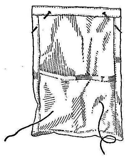
Tying Paper Bag to Make a Carrying Handle
Stages in Tying a Bag
In tying the ordinary paper bag, the string can be placed in the
paper in such a way that it will form a handle to carry the
package, and also prevent any leakage of the contents. The bag
must be long enough for the end to fold over as shown in Fig. 1.
The folds are made over the string, as in Fig. 2. The string is
then tied, Fig. 3, to form a handle, Fig. 4.
Contributed by James M. Kane, Doylestown, Pa.
Equilibrator for Model Aeroplanes
Warping the Aeroplane Wings
On one of my model aeroplanes I placed an equilibrator to keep it
balanced. The device was attached to a crosspiece fastened just
below the propeller between the main frame uprights. A stick was
made to swing on a bolt in the center of the crosspiece to which
was attached a weight at the lower end and two lines connecting
the ends of the planes at the upper end. These are shown in Fig.
1. When the aeroplane tips, as shown in Fig. 2, the weight draws
the lines to warp the plane so it will right itself
automatically.
Contributed by Louis J. Day, Floral Park, N. Y.
Repairing Christmas-Tree Decorations
Small glass ornaments for Christmas tree decorations are very
easily broken on the line shown in the sketch. These can be
easily repaired by inserting in the neck a piece of match,
toothpick or splinter of wood and tying the hanging string to it.
Homemade Scroll Saw
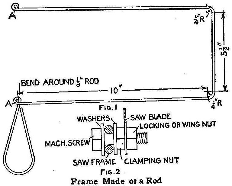
Frame Made of a Rod
A scroll saw, if once used, becomes indispensable in any home
carpenter chest, yet it is safe to say that not one in ten
contains it. A scroll saw is much more useful than a keyhole saw
for sawing small and irregular holes, and many fancy
knick-knacks, such as brackets, bookracks and shelves can be made
with one.
A simple yet serviceable scroll saw frame can be made from a
piece of cold-rolled steel rod, 3/32 or 1/4 in. in diameter, two
1/8-in. machine screws, four washers and four square nuts. The
rod should be 36 or 38 in. long, bent as shown in Fig. 1. Place
one washer on each screw and put the screws through the eyelets,
AA, then place other washers on and fasten in place by screwing
one nut on each screw, clamping the washers against the frame as
tightly as possible. The saw, which can be purchased at a local
hardware store, is fastened between the clamping nut and another
nut as shown in Fig. 2.
If two wing nuts having the same number and size of threads are
available, use them in place of the outside nuts. They are easier
to turn when inserting a saw blade in a hole or when removing
broken blades.
Contributed by W. A. Scranton, Detroit, Michigan.
How to Make a Watch Fob
Watch Fob
The fixtures for the watch fob shown—half size—may be made of
either brass, copper, or silver. Silver is the most desirable
but, of course, the most expensive. The buckle is to be
purchased. The connection is to be of leather of a color to
harmonize with that of the fixtures. The body of the fob may be
of leather of suitable color or of silk. Of the leathers, green
and browns are the most popular, though almost any color may be
obtained.
Make full size drawings of the outline and design of the
fixtures. With carbon paper trace these on the metal. Pierce the
metal of the parts that are to be removed with a small hand drill
to make a place for the leather or silk. With a small metal saw
cut out these parts and smooth up the edges, rounding them
slightly so they will not cut the leather or silk. Next cut out
the outlines with the metal shears. File these edges, rounding
and smoothing with emery paper. The best way of handling the
decorative design is to etch it and, if copper or brass, treat it
with color.
For etching, first cover the metal with black asphaltum varnish,
on the back and all the parts that are not to be touched with the
acid. In the design shown, the unshaded parts should not be
etched and should, therefore, be covered the same as the back.
Apply two coats, allowing each time to dry, after which immerse
the metal in a solution prepared as follows: 3 parts water, 1
part nitric acid,
1 part sulphuric acid. Allow the metal to
remain in this until the acid has eaten to a depth of 1/32 in.,
then remove it and clean in a turpentine bath, using a swab and
an old stiff brush. The amount of time required to do the etching
will depend upon the strength of the liquid, as well as the depth
of etching desired.
For coloring silver, as well as brass and copper, cover the metal
with a solution of the following: 1/2 pt. of water in which
dissolve, after breaking up, five cents worth of sulphureted
potassium. Put a teaspoonful of this into a tin with 2 qt. of
water. Polish a piece of scrap metal and dip it in the solution.
If it colors the metal red, it has the correct strength. Drying
will cause this to change to purple. Rub off the highlights,
leaving them the natural color of the metal and apply a coat of
banana-oil lacquer.
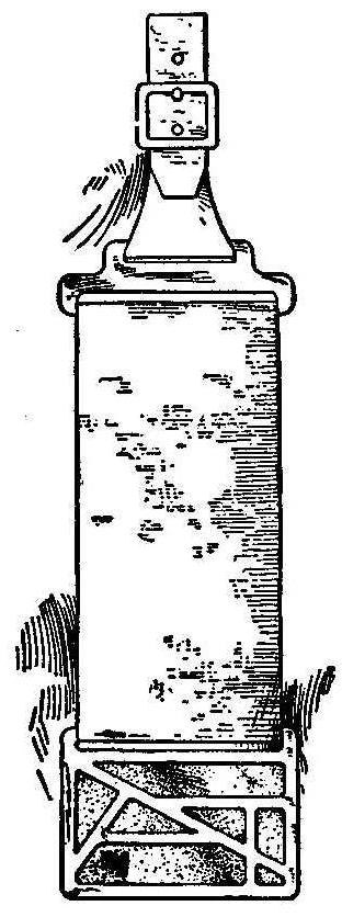
An Austrian Top
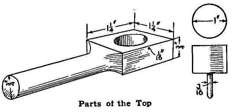
Parts of the Top
All parts of the top are of wood and they are simple to make. The
handle is a piece of pine, 5-1/4 in. long, 1-1/4 in. wide and 3/4
in. thick. A handle, 3/4 in. in diameter, is formed on one end,
allowing only 1-1/4 in. of the other end to remain rectangular in
shape. Bore a 3/4-in. hole in this end for the top. A 1/16-in.
hole is bored in the edge to enter the large hole as shown. The
top can be cut from a broom handle or a round stick of hardwood.
To spin the top, take a piece of stout cord about 2 ft. long,
pass one end through the 1/16-in. hole and wind it on the small
part of the top in the usual way, starting at the bottom and
winding upward. When the shank is covered, set the top in the
3/4-in. hole. Take hold of the handle with the left hand and the end
of the cord with the right hand, give a good quick pull on the
cord and the top will jump clear of the handle and spin
vigorously.
Contributed by J.F. Tholl, Ypsilanti, Michigan.
Pockets for Spools of Thread
Pockets for Thread
A detachable pocket for holding thread when sewing is shown
herewith. The dimensions may be varied to admit any number or
size of spools. Each pocket is made to take a certain size spool,
the end of the thread being run through the cloth front for
obtaining the length for threading a needle. This will keep the
thread from becoming tangled and enable it always to be readily
drawn out to the required length.
Contributed by Miss L. Alberta Norrell, Augusta, Ga.
Cleaning Leather on Furniture
Beat up the whites of three eggs carefully and use a piece of
flannel to rub it well into the leather which will become clean
and lustrous. For black leathers, some lampblack may be added and
the mixture applied in the same way.
A Baking Pan
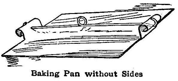
Baking Pan without Sides
When making cookies, tarts or similar pastry, the housewife often
wishes for something by which to lift the baked articles from the
pan. The baking tray or pan shown in the sketch not only protects
the hands from burns but allows the baked articles easily to slip
from its surface. The pan is made from a piece of sheet iron
slightly larger than the baking space desired. Each end of the
metal is cut so that a part may be turned up and into a roll to
make handles for the pan.
A wire or small rod is placed between the handles as shown. This
wire is fastened at each end and a loop made in the center. The
pan can be removed from the oven by placing a stick through the
loop and lifting it out without placing the hands inside the hot
oven. The baking surface, having no sides, permits the baked
articles to be slid off at each side with a knife or fork.
A. A. Houghton, Northville, Mich.
A Broom Holder
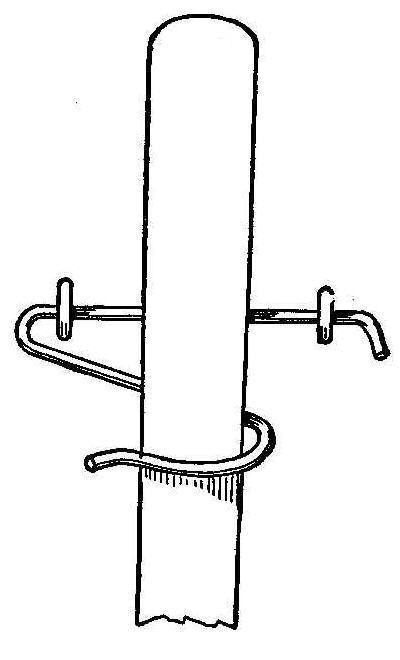
A very simple and effective device for holding a broom when it is
not in use is shown in the sketch. It is made of heavy wire and
fastened to the wall with two screw eyes, the eyes forming
bearings for the wire. The small turn on the end of the straight
part is to hold the hook out far enough from the wall to make it
easy to place the broom in the hook. The weight of the broom
keeps it in position.
Contributed by Irl Hicks, Centralia, Mo.
Stringing Wires
A string for drawing electric wires into bent fixtures can be
easily inserted by rolling it into a small ball and blowing it
through while holding one end.
A Darkroom Lantern
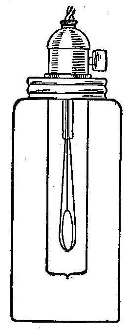
Darkroom Lantern
Procure an ordinary 2-qt. glass fruit jar, break out the
porcelain lining in the cover and cut a hole through the metal,
just large enough to fit over the socket of an incandescent
electric globe, then solder cover and socket together, says
Studio Light. Line the inside of the jar with two thicknesses of
good orange post office paper. The best lamp for the purpose is
an 8-candlepower showcase lamp, the same as shown in the
illustration. Screw the lamp into the socket and screw the cover
onto the jar, and you have a safe light of excellent illuminating
power.
When you desire to work by white light, two turns will
remove the jar.
If developing papers are being worked, obtain a second jar and
line with light orange paper, screw into the cover fastened to
the lamp and you have a safe and pleasant light for loading and
development. By attaching sufficient cord to the lamp, it can be
moved to any part of the darkroom, and you have three lamps at a
trifling cost.
Preventing Vegetables from Burning in a Pot
Many housekeepers do not know that there is a simple way to
prevent potatoes from burning and sticking to the bottom of the
pot. An inverted pie pan placed in the bottom of the pot avoids
scorching potatoes. The water and empty space beneath the pan
saves the potatoes. This also makes the work of cleaning pots
easier as no adhering parts of potatoes are left to be scoured
out.
A Clothes Rack
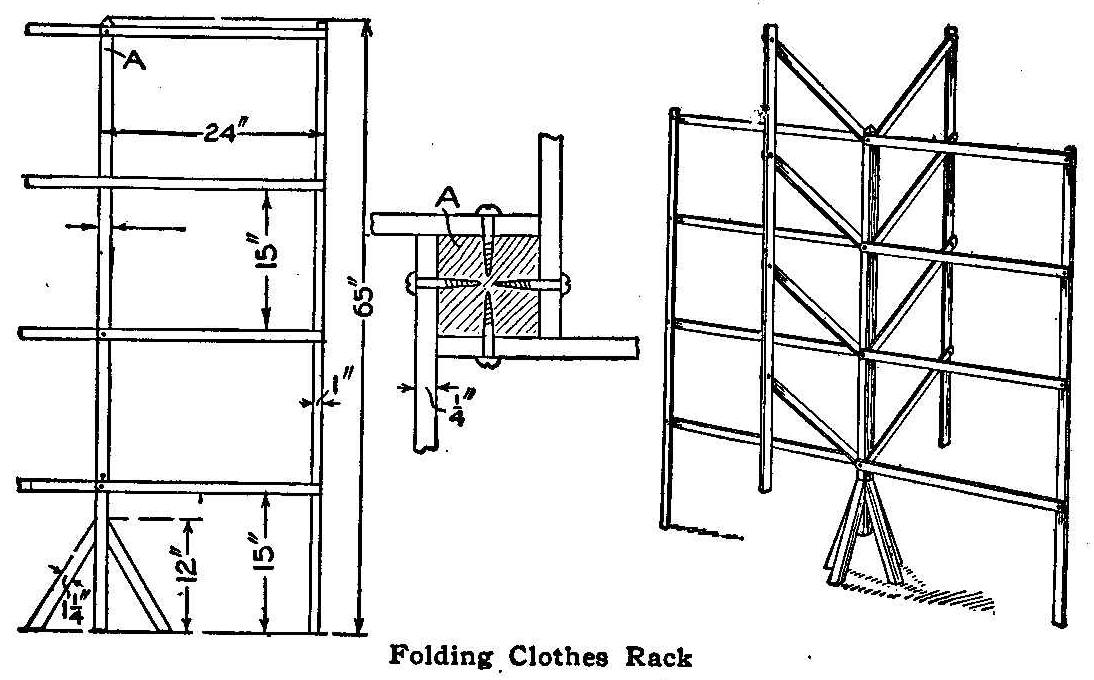
Folding Clothes Rack
A clothes-drying rack that has many good features can be made as
shown in the illustration. When the rack is closed it will fit
into a very small space and one or more wings can be used at a
time as the occasion or space permits, and not tip over. The rack
can be made of any hard wood and the material list is as follows:
1 Center post. 1-1/4 in. square by 62 in.
4 Braces. 1-1/4 in. square by 12 in.
16 Horizontal bars. 1 by 1-1/4 by 24 in.
4 Vertical pieces. 1/4 by 1 by 65 in.
Attach the four braces for the feet with finishing nails after
applying a good coat of glue.
The horizontal bars are fastened to the vertical pieces with
rivets using washers on both sides. The holes are bored a little
large so as to make a slightly loose joint. The other ends of the
bars are fastened to the center post with round head screws. They
are fastened, as shown in the cross-section sketch, so it can be
folded up.
Contributed by Herman Fosel, Janesville, Wis.
Homemade Shower Bath
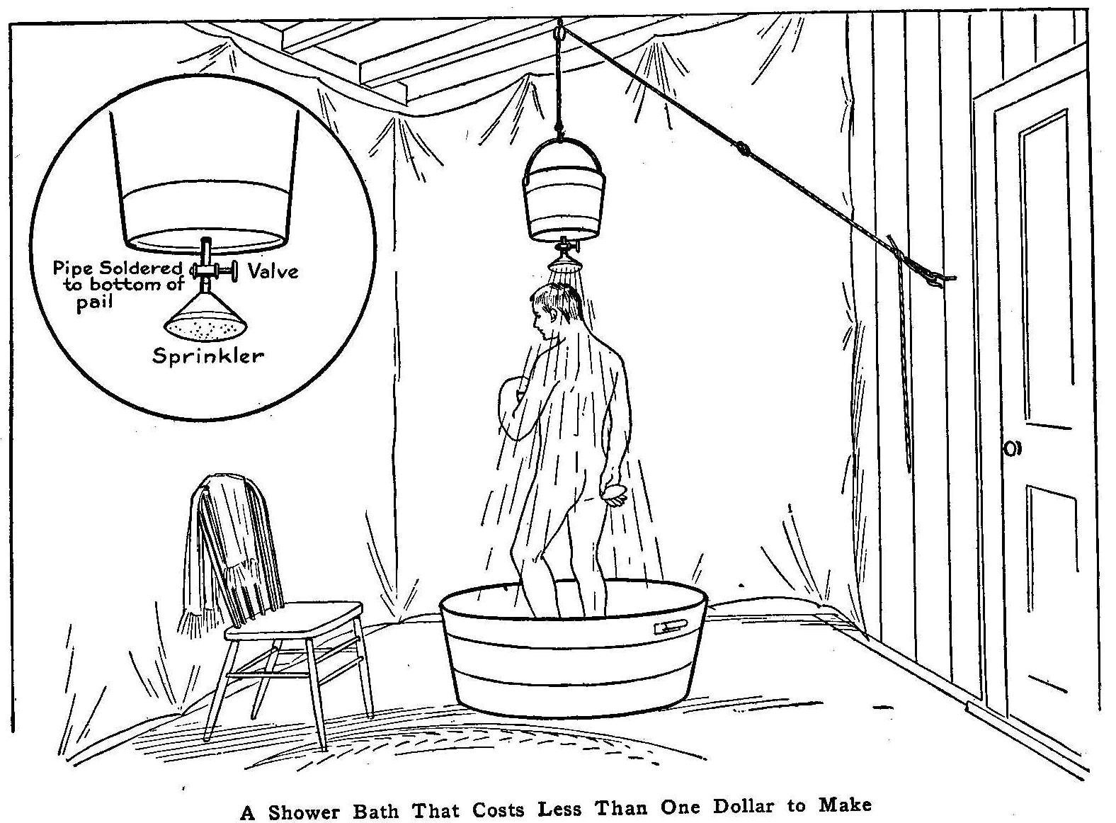
A Shower Bath That Costs Less Than One Dollar to Make
While in the country during vacation time, I missed my daily bath
and devised a shower bath that gave complete satisfaction. The
back porch was enclosed with sheeting for the room, and the
apparatus consisted of a galvanized-iron pail with a short nipple
soldered in the center of the bottom and fitted with a valve and
sprinkler. The whole, after filling the pail with water, was
raised above one’s head with a rope run over a pulley fastened to
the roof of the porch, and a tub was used on the floor to catch
the water. A knot should be tied in the rope at the right place,
to keep it from running out of the pulley while the pail is
lowered to be filled with water, and a loop made in the end,
which is placed over a screw hook turned into the wall. If the
loop is tied at the proper place, the pail will be raised to the
right height for the person taking the shower bath.
The water will run from 10 to 15 minutes. The addition of some
hot water will make a splendid shower bath.
Contributed by Dr. C. H. Rosenthal, Cincinnati, O.
How to Make Small Sprocket Wheels
As I needed several small sprocket wheels and had none on hand, I
made them quickly without other expense than the time required,
from scrap material. Several old hubs with the proper size bore
were secured. These were put on an arbor and turned to the size
of the bottom of the teeth. Hole were drilled and tapped to
correspond to the number of teeth required and old stud bolts
turned into them. The wheels were again placed on the arbor and
the studs turned to the required size. After rounding the ends of
the studs, the sprockets were ready for use and gave perfect
satisfaction.
Contributed by Charles Stem, Phillipsburg, New York.
Pot-Cover Closet
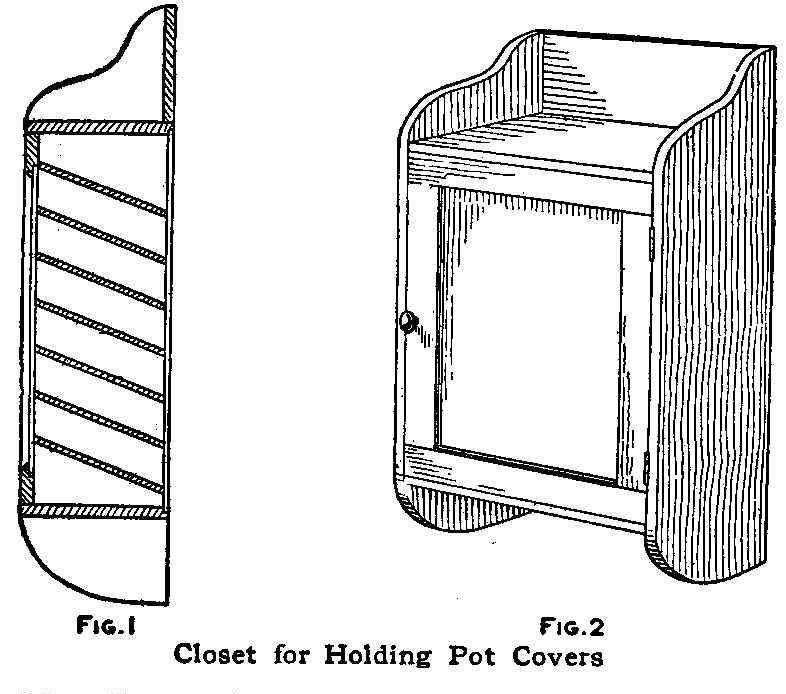
FIG. 1
FIG. 2
Closet for Holding Pot Covers
The sides of the cover closet are cut as shown in Fig. 1 and
shelves are nailed between them at a slight angle. No dimensions
are given as the space and the sizes of the covers are not always
the same. The back is covered with thin boards placed vertically.
The front can be covered with a curtain or a paneled door as
shown.
Contributed by Gilbert A. Wehr, Baltimore, Md.
Aid in Mixing Salad Dressing
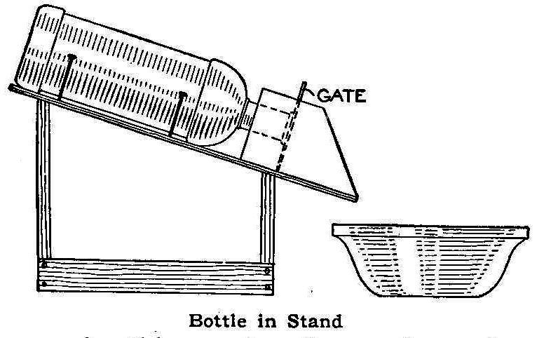
Bottle in Stand
Some cooks find it a very difficult matter to prepare salad
dressing, principally mayonnaise dressing, as the constant
stirring and pouring of oil and liquids are required in the
operation. The simple homemade device shown in the accompanying
sketch greatly assists in this work. It consists of a stand to
hold a bottle, the mouth of which rests against a small gate
directly in the rear of the attached tin trough. The weight of
the bottle and the contents against the gate serves as a check or
stopper. If the gate is raised slightly, it will permit a
continuous flow of liquid of the desired amount.
Saving Overexposed Developing Prints
In using developing papers, either for contact printing or
enlargements, you are, by all rules of the game, entitled to a
certain number of overexposed prints, says a correspondent of
Camera Craft. But there is no reason why you should lose either
the paper or the time and trouble expended in making these
prints. By using the following method, you can turn these very
dark prints into good ones.
First: these overexposed prints must be fully developed. Do not
try to save them by rushing them out of the developer into the
short-stop or fixing bath. The results will be poor, and, if you
try to tone them afterward, the color will be an undesirable,
sickly one. Develop them into strong prints, thoroughly fix, and
wash until you are sure all hypo is removed. In my own practice,
I carry out this part of the work thoroughly, then dry the prints
and lay aside these dark ones until there is an accumulation of a
dozen or more, doing this to avoid too frequent use of the very
poisonous bleaching solution. The bleacher is made up as follows
and should be plainly marked “Poison.”
| Cyanide of potassium | 2 oz. |
| Iodide of potassium | 20 gr. |
| Water | 16 oz. |
Place the dry print, without previous wetting, in this solution.
It will bleach slowly and evenly, but, when it starts to bleach,
transfer it to a tray of water, where it will continue to bleach.
When the desired reduction has taken place, stop the action at
once by immersing the print in a 10-per-cent solution of borax.
The prints may be allowed to remain in this last solution until
they are finished. A good final washing completes the process.
This washing must be thorough and a sponge or a tuft of cotton
used to clean the surface of the print.
With a little practice, this method of saving prints that are too
dark becomes easy and certain. The prints are lightened and at
the same time improved in tone, being made blue-black with a
delicate and pleasing quality that will tempt you to purposely
overexpose some of your prints in order to tone them by this
method for certain effects. The process is particularly valuable
to the worker in large sizes, as it provides a means of making
quite a saving of paper that would otherwise be thrown away.
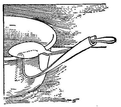
An Ironing-Board Stand
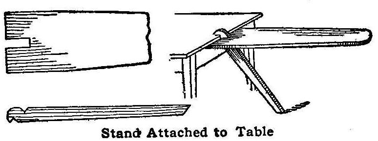
Stand Attached to Table
An ordinary ironing board is cut square on the large end and a
slot cut 1-1/2 in. wide and 4 in. long to admit the angle
support. The support is placed against the table and the board is
pressed down against the outer notch which jams against the
table, thus holding the board rigid and in such a position as to
give free access for ironing dresses, etc.
Contributed by T. L. Gray, San Francisco, Cal.
A Desk Blotting Pad
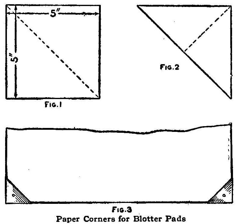
Fig 3 Paper Corners for Blotter Pads
Procure four sheets of blotting paper, preferably the colored
kind, as it will appear clean much longer than the white. The
size of the pad depends on the size of the blotting paper.
Fold four pieces of ordinary wrapping paper, 5 by 15 in. in size,
three times, to make it 5 by 5 in. Fold each one from corner to
corner as shown in Fig. 1 and again as in Fig. 2. Paste the last
fold together and the corner holders are complete. Put one on
each corner of the blotting paper. They can be fastened with a
small brass paper fastener put through the top of the holder. The
blotting paper can be easily changed by removing the holders and
fasteners. Corners complete are shown in Fig. 3.
Contributed by J. Wilson Aldred Toronto, Canada.
Sleeve Holders for Lavatories
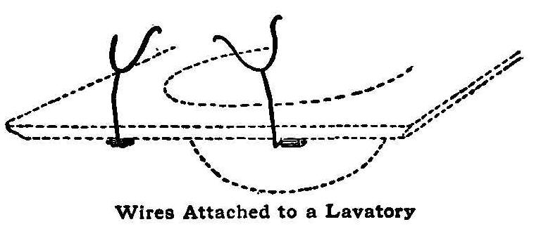
Wires Attached to a Lavatory
A very handy article is an attachment on wash basins or
lavatories for holding the sleeves back while washing the hands.
It is very annoying to have the sleeves continually slip down and
become wet or soiled. The simple device shown herewith can be
made with bent wires or hooks and attached in such a way that it
can be dropped out of the way when not in use.
Contributed by L. J. Monahan, Oshkosh, Wisconsin.
Removing Tarnish
A pencil eraser will remove the tarnish from nickel plate, and
the ink eraser will remove the rust from drawing instruments.
How to Make a Brass Bookmark
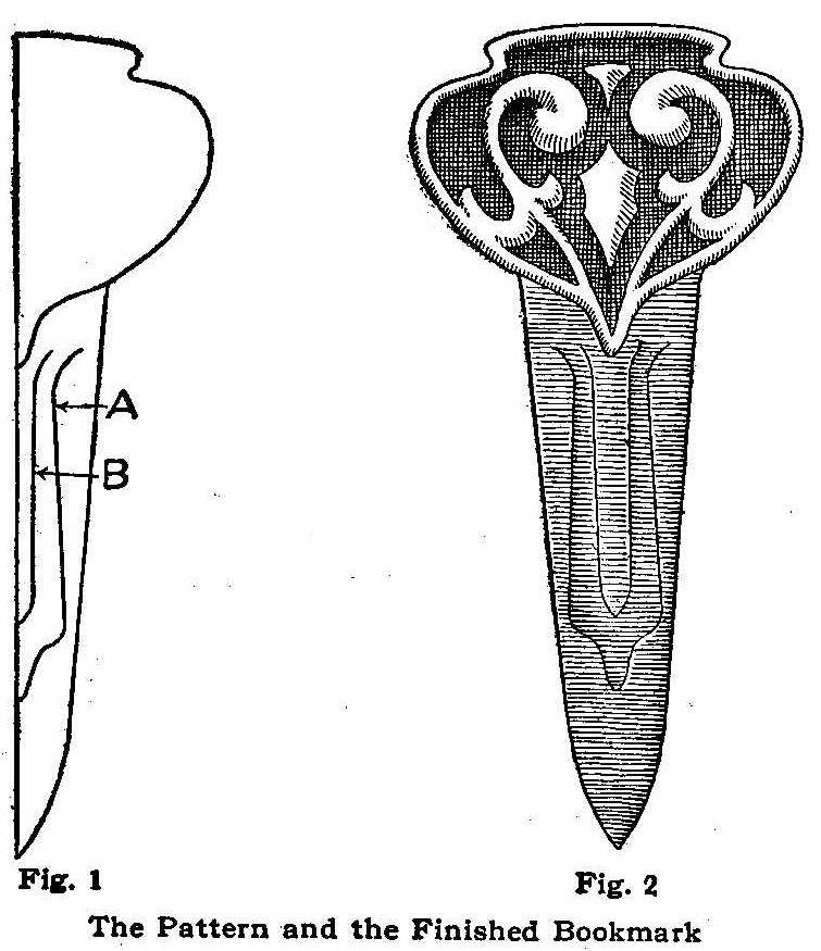
Fig. 1 Fig. 2
The Pattern and the Finished Bookmark
Secure a piece of brass of No. 20 gauge, having a width of 2-1/4
in. and a length of 5 in. Make a design similar to that shown,
the head of which is 2 in. wide, the shaft 1 in. wide below the
head and the extreme length 4-1/2 in. Make one-half of the
design, as shown in Fig. 1, freehand, then trace the other half
in the usual way, after folding along the center line. Trace the
design on the metal, using carbon paper, which gives the outline
of the design Fig. 2.
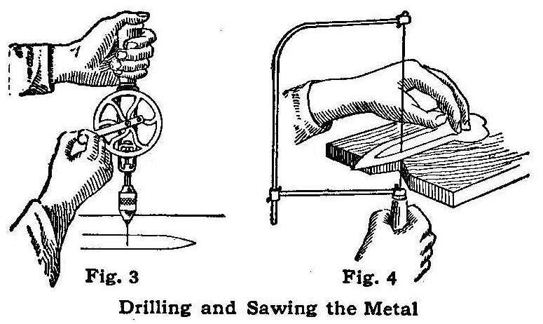
Drilling and Sawing the Metal
With the metal shears, cut out the outline as indicated by the
drawing. With files, smooth off any roughness and form the edge
so that it shall be nicely rounded.
The parts of the design in heavy color may be treated in several
ways. A very satisfactory treatment is obtained by etching, then
coloring. Clean the metal thoroughly with pumice stone and water
or with alcohol before the design is applied. Cover all the metal
that is not to be lowered with a thick coating of asphaltum.
Allow this to dry, then put on a second coat. After this has
dried, thoroughly immerse the metal in a solution composed as
follows: 3 parts water, 1 part sulphuric acid,
1 part nitric acid.
Allow the metal to remain in this solution until the exposed part
has been eaten about 1/32 in. deep, then remove it and clean off
the asphaltum, using turpentine. Do not put the hands in the
solution, but use a swab on a stick.
For coloring olive green, use 2 parts water to 1 part permuriate
of iron. Apply with a small brush.
The lines at A and B will need to be cut, using a small metal
saw. Pierce a hole with a small drill, Fig. 3, large enough to
receive the saw and cut along the lines as in Fig. 4. A piece of
wood with a V-shaped notch which is fastened firmly to the bench
forms the best place in which to do such sawing. The teeth of the
saw should be so placed that the sawing will be done on the
downward stroke. The metal must be held firmly, and the saw
allowed time to make its cut, being held perpendicular to the
work.
After the sawing, smooth the edges of the metal with a small file
and emery paper. The metal clip may be bent outward to do this
part of the work.
Cheesebox-Cover Tea Tray
The cover from a cheesebox can be converted into a tea tray that
is very dainty for the piazza, or for serving an invalid’s
breakfast.
First sandpaper the wood until it is smooth, then stain it a
mahogany color. The mahogany stain can be obtained ready
prepared. After the stain has dried, attach brass handles, which
can be obtained for a small sum at an upholsterer’s shop. A round
embroidered doily in the bottom adds to the appearance of the
tray.
Contributed by Katharine D. Morse, Syracuse, New York.
Piercing-Punch for Brass
Drill a 1/2-in. hole through a block of pine or other soft wood 2
in. thick. Tack over one end of the hole a piece of pasteboard in
which seven coarse sewing-machine needles have been inserted. The
needles should be close together and pushed through the
pasteboard until the points show. The hole is then filled with
melted babbitt metal. When this is cold, the block is split and
the pasteboard removed. This tool makes neat pierced work and in
making brass shades, it does the work rapidly.
Contributed by H. Carl Cramer, East Hartford, Conn.
Kitchen Chopping Board
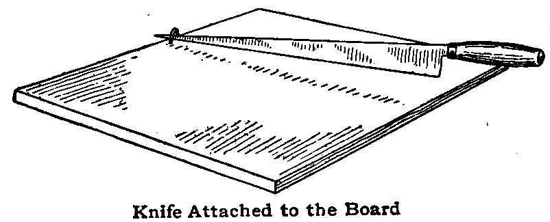
Knife Attached to the Board
Cooks can slice, chop or mince vegetables and various other food
rapidly by placing the little device, as shown, on a chopping
board. Ii is an ordinary staple, driven in just far enough to
allow a space for the end of an ordinary pointed kitchen knife to
fit in it. The staple is driven in the edge of the chopping
board. The knife can be raised and lowered with one hand, as the
material is passed under the blade with the other. Great pressure
can be applied and the knife will not slip.
Contributed by M. M. Burnett, Richmond, Cal.
Carrying Mattresses
Sew straps to the sides of mattresses and they can be handled
much easier.
A Carpenter’s Gauge
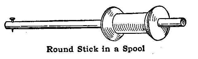
Round Stick In a Spool
The home workshop can be supplied with a carpenter’s gauge
without any expense’ by the use of a large spool and a round
stick of wood. The stick should be dressed to fit the hole in the
spool snugly and a small brad driven through one end so that the
point will protrude about 1/16 in.
The adjustment of the gauge is secured by driving the stick in
the hole in the direction desired. A better way and one that will
make the adjusting easy is to file the point end of a screw eye
flat and use it as a set screw through a hole in the side of the
spool.
A Flatiron Rest
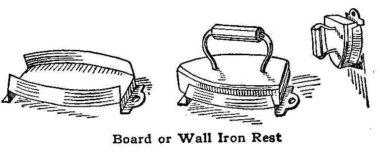
Board or Wall Iron Rest
The iron rest and wall hanger shown in the sketch is made of
sheet iron. The upturned edges of the metal are bent to fit the
sloping sides of the iron. The holder and iron can be moved at
the same time.
Contributed by W. A. Jaquythe, Richmond, Cal.
Use for Paper Bags
When groceries are delivered, save the paper bags and use them
for staring bread and cakes. Tie the neck of the bag with a
string and it will keep the contents fresh and clean.
Contributed by Mrs. L. H. Atwell, Kissimmee, Florida.
Use Chalk on Files
If a little chalk is rubbed on a file before filing steel, it
will keep the chips from sticking in the cuts on the file and
scratching the work.
A Homemade Steam Turbine
By William H. Warnecke
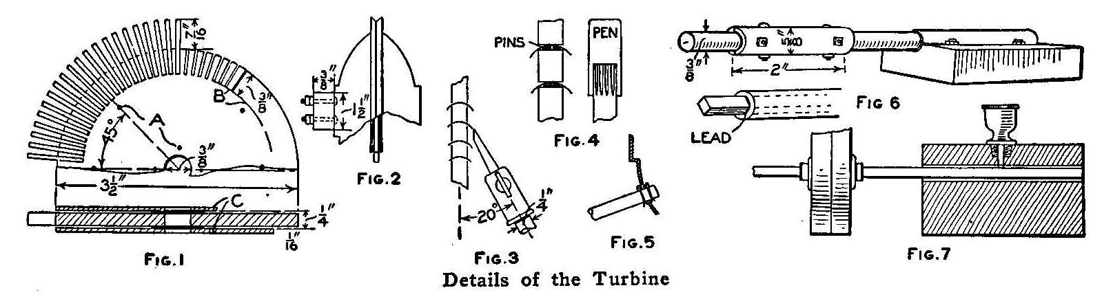
Details of the Turbine
Procure some brass, about 3/16 in. thick and 4 in. square; 53
steel pens, not over 1/4 in. in width at the shank; two enameled,
or tin, saucers or pans, having a diameter on the inside part of
about 4-1/2 in.; two stopcocks with 1/8 in. holes; one shaft;
some pieces of brass, 1/4 in. thick, and several 1/8-in. machine
screws.
Lay out two circles on the 3/16-in. brass, one having a diameter
of 3-1/2 in. and the other with a diameter of 2-3/4 in. The
outside circle is the size of the finished brass wheel, while the
inside circle indicates the depth to which the slots are to be
cut. Mark the point where a hole is to be drilled for the shaft,
also locate the drill holes, as shown at A, Fig. 1. After the
shaft hole and the holes A are drilled in the disk, it can be
used as template for drilling the side plates C.
The rim of the disk is divided into 53 equal parts and radial
lines drawn from rim to line B, indicating the depth of the
slots. Slots are cut in the disk with a hacksaw on the radial
lines. A small vise is convenient for holding the disk while
cutting the slots. When cutting the disk out of the rough brass,
sufficient margin should be left for filing to the true line. The
slots should be left in their rough state as they have a better
hold on the pens which are used for the blades. The pens are
inserted in the slots and made quite secure by forcing ordinary
pins on the inside of the pens and breaking them off at the rim,
as shown in Fig. 4.
When the pens are all fastened two pieces of metal are provided,
each about 1 in. in diameter and 1/32 in. thick, with a 3/8-in.
hole in the center, for filling pieces which are first placed
around the shaft hole between the disk and side plates C, Fig. 1.
The side plates are then secured with some of the 1/8-in. machine
screws, using two nuts on each screw. The nuts should be on the
side opposite the inlet valves. The shaft hole may also be filed
square, a square shaft used, and the ends filed round for the
bearings.
The casing for the disk is made of two enameled-iron saucers,
Fig. 2, bolted together with a thin piece
of asbestos between
them to make a tight joint. A 3/4-in. hole is cut near the edge
of one of the saucers for the exhaust. If it is desired to carry
the exhaust beyond the casing, a thin pipe can be inserted 1/4
in. into the hole. Holes are drilled through the pipe on both
inside and outside of the casing, and pins inserted, as shown in
Fig. 5. Solder is run around the outside pin to keep the steam
from escaping. At the lowest point of the saucer or casing a
1/8-in. hole is drilled to run off the water. A wood plug will
answer for a stopcock.
If metal dishes, shaped from thick material with a good coating
of tin, can be procured, it will be much easier to construct the
casing than if enameled ware is used. The holes can be easily
drilled and the parts fitted together closely. All seams and
surfaces around fittings can be soldered.
Nozzles are made of two stopcocks having a 1/8-in. hole. These
are connected to a 3/8-in. supply pipe. The nozzles should be set
at an angle of 20 deg. with the face of the disk. The nozzle or
stopcock will give better results if the discharge end is filed
parallel to the face of the disk when at an angle of 20 deg.
There should be a space of 1/16 in. between the nozzle and the
blades to allow for sufficient play, Fig. 3.
The bearings are made of 1/4-in. brass and bolted to the casing,
as shown, with 1/8-in. machine screws and nuts. Two nuts should
be placed on each screw. The pulley is made by sliding a piece of
steel pipe on the engine shaft and fastening it with machine
screws and nuts as shown in Fig. 6. If the shaft is square,
lead
should be run into the segments.
The driven shaft should have a long bearing. The pulley on this
shaft is made of pieces of wood nailed together, and its
circumference cut out with a scroll saw. Flanges are screwed to
the pulley and fastened to the shaft as shown in Fig. 7.
The bearings are made of oak blocks lined with heavy tin or sheet
iron for the running surface. Motion is transmitted from the
engine to the large pulley by a thin but very good leather belt.
Homemade Telegraph Key
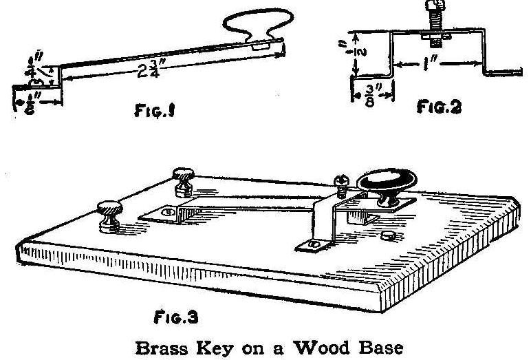
Brass Key on a Wood Base
A simple and easily constructed telegraph key may be made in the
following manner: Procure a piece of sheet brass, about 1/32 in.
thick, and cut out a strip 3-1/2 in. long by 3/4 in. wide. Bend
as shown in Fig. 1 and drill a hole for the knob in one end and a
hole for a screw in the other. Procure a small wood knob and
fasten it in place with a small screw. Cut a strip of the same
brass 2-3/4 in. long and 5/16 in. wide and bend as shown in Fig.
2. Drill two holes in the feet for screws to fasten it to the
base, and one hole in the top part for a machine screw, and
solder a small nut on the under side of the metal over the hole.
Mount both pieces on a base 4-1/4 by 2-3/4 by 1/4 in., as in Fig.
3, and where the screw of the knob strikes the base when pressed
down, put in a screw or brass-headed tack for a contact. Fasten
the parts down with small brass wood-screws and solder the
connections beneath the base. Binding posts from an old battery
cell are used on the end of the base. The screw on top of the
arch is used to adjust the key for a long or short
stroke.
Contributed by S. V. Cooke, Hamilton, Canada.
Keeping Food Cool in Camps
Camps and suburban homes located where ice is hard to get can be
provided with a cooling arrangement herein described that will
make a good substitute for the icebox. A barrel is sunk in the
ground in a shady place, allowing plenty of space about the
outside to fill in with gravel. A quantity of small stones and
sand is first put in wet. A box is placed in the hole over the
top of the barrel and filled in with clay or earth well tamped.
The porous condition of the gravel drains the surplus water after
a rain.
The end of the barrel is fitted with a light cover and a heavy
door hinged to the box. A small portion of damp sand is sprinkled
on the bottom of the barrel. The covers should be left open
occasionally to prevent mold and to remove any bad air that may
have collected from the contents.
Contributed by F. Smith, La Salle, Ill.
Homemade Work Basket
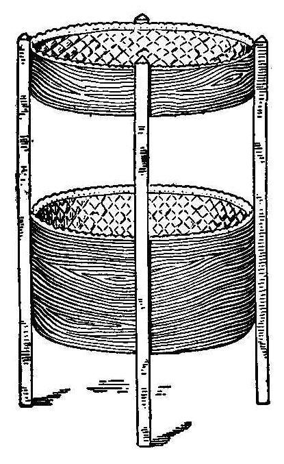
Secure a cheese box about 12 in. high and 15 in. or more in
diameter. It will pay you to be careful in selecting this box. Be
sure to have the cover. Score the wood deeply with a carpenter’s
gauge inside and out 3-1/2 in. from the top of the box. With
repeated scoring the wood will be almost cut through or in shape
to finish the cut with a knife. Now you will have the box in two
pieces. The lower part, 8-1/2 in. deep over all, we will call the
basket, and the smaller part will be known as the tray.
Remove the band from the cover and cut the boards to fit in the
tray flush with the lower edge, to make the bottom. Fasten with
3/4-in brads. The kind of wood used in making these boxes cracks
easily and leaves a rough surface which should be well
sandpapered.
The four legs are each 3/4-in. square and 30-1/2 in. long. The
tops should be beveled to keep them from splintering at the
edges. With a string or tape measure, find the circumference of
the tray or basket and divide this into four equal parts,
arranging the lap seam on both to come midway between two of the
marks. When assembling, make these seams come between the two
back legs.
The tray is placed 1-1/4 in. from the top end and the basket
6-3/4 in. from the bottom end of the legs. Notch the legs at the
lower point about 1/8 in. deep and 1-1/4 in. wide to receive the
band at the lower end of the basket. Fasten with 3/4-in. screws,
using four to each leg, three of which are in the basket. Insert
the screws from the inside of the box into the legs.
Stain the wood before putting in the lining. If all the parts are
well sandpapered, the wood will take the stain nicely: Three
yards of cretonne will make a very attractive lining. Cut two
sheets of cardboard to fit in the bottom of the tray and basket.
Cover them with the cretonne, sewing on the back side. Cut four
strips for the sides from the width of the goods 5-1/2 in. wide
and four strips 10 in. wide. Sew them end to end and turn down
one edge to a depth of 1 in. and gather it at that point,—also
the lower edge when necessary. Sew on to the covered cardboards.
Fasten them to the sides of the tray and basket with the smallest
upholsterers’ tacks. The product of your labor will be a very
neat and useful piece of furniture.
Contributed by Stanley H. Packard, Boston, Mass.
A Window Display
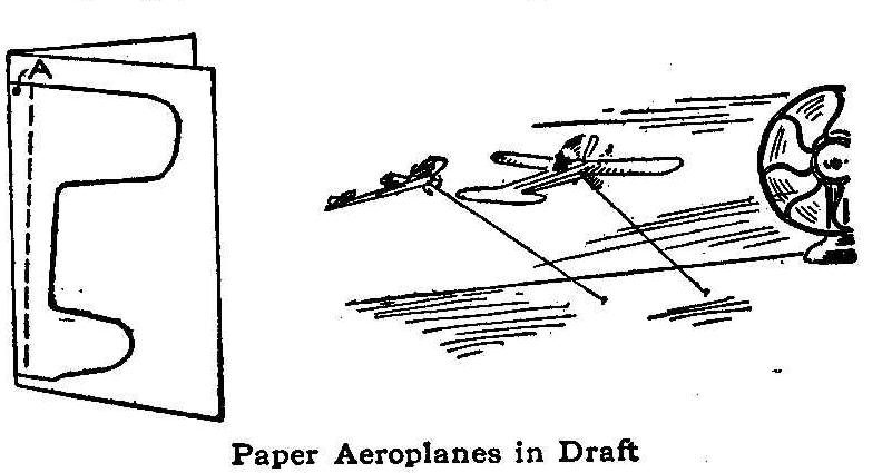
Paper Aeroplanes in Draft
A novel and attractive aeroplane window display can be easily
made in the following manner: Each aeroplane is cut from folded
paper, as shown in the sketch, and the wings bent out on the
dotted lines. The folded part in the center is pasted together.
Each aeroplane is fastened with a small thread from the point A
as shown. A figure of an airman can be pasted to each aeroplane.
One or more of the aeroplanes can be fastened in the blast of an
electric fan and kept in flight the same as a kite. The fan can
be concealed to make the display more real. When making the
display, have the background of such a color as to conceal the
small threads holding the aeroplanes.
Contributed by Frederick Hennighausen, Baltimore, Md.
How to Make a Flint Arrowhead
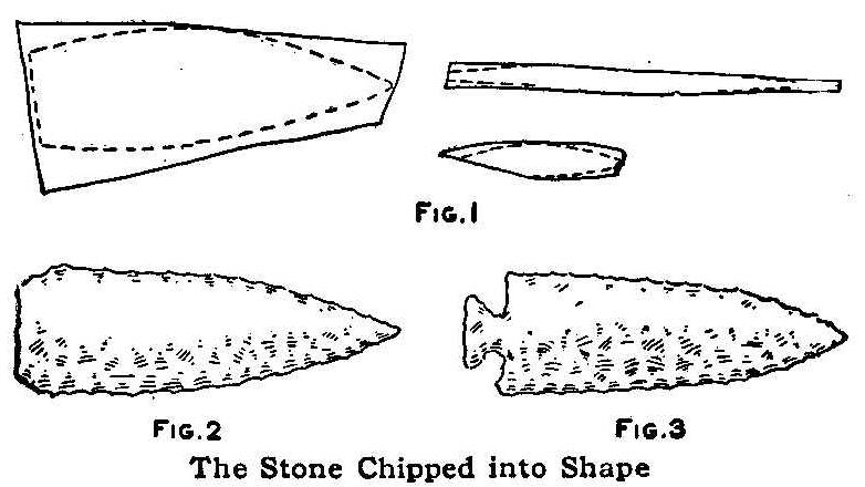
Fig.2 Fig.3
The Stone Chipped into Shape
If you live where flints abound, possess the requisite patience
and the knack of making things, you can, with the crudest of
tools and a little practice, chip out as good arrowheads as any
painted savage that ever drew a bow. Select a piece of
straight-grained flint as near the desired shape as possible. It
may be both longer and wider than the finished arrow but it
should not be any thicker. The side, edge and end views of a
suitable fragment are shown in Fig. 1. Hold the piece with one
edge or end resting on a block of wood and strike the upper edge
lightly with a hammer, a small boulder or anything that comes
handy until the piece assumes the shape shown in Fig. 2.
The characteristic notches shown in the completed arrow, Fig. 3,
are chipped out by striking the piece lightly at the required
points with the edge of an old hatchet or a heavy flint held at
right angles to the edge of the arrow. These heads can be made so
that they cannot be distinguished from the real Indian
arrowheads.
Contributed by B. Orlando Taylor, Cross Timbers, Mo.
An Opening Handle for a Stamp Pad
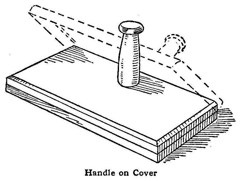
Handle on Cover
A stamp pad is a desk necessity and the cleanliness of one
depends on keeping it closed when it is not in use. The opening
and closing of a pad requires both hands and consequently the
closing of a pad is often neglected in order to avoid soiling the
fingers. This trouble can be avoided if the pad is fitted with a
small handle as shown in the sketch. Take the ordinary pad and
work the hinge until it opens freely. If necessary apply a little
oil and spread the flanges of the cover slightly.
Saw off the top of a common wood clothespin just above the slot,
saving all the solid part. Fasten this to the cover near the back
side in an upright position with a screw. A tap on the front side
of the pin will turn it over backward until the head rests on the
desk thus bringing the cover up in the upright position. When
through using the pad, a slight tap on the back side of the cover
will turn it down in place.
Contributed by H. L. Crockett, Gloversville, N. Y.
Concrete Kennel
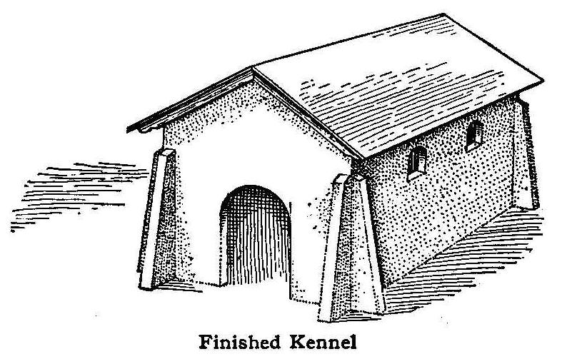
Finished Kennel
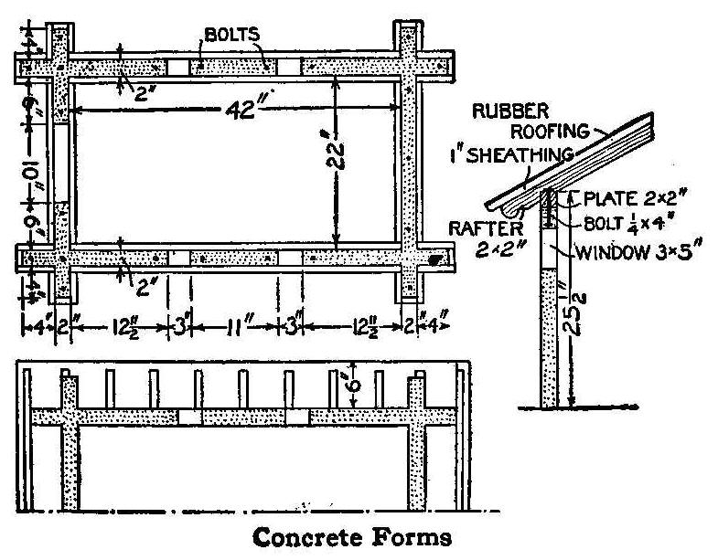
Concrete Forms
The kennel shown in the illustration is large enough for the
usual size of dog. It is cleanly, healthful and more ornamental
than the average kennel. This mission style would be in keeping
with the now popular mission and semi-mission style home, and,
with slight modifications, it could be made to conform with the
ever beautiful colonial home. It is not difficult to build and
will keep in good shape for many years.
The dimensions and the manner of making the forms for the
concrete, and the location for the bolts to hold the plate and
rafters, are shown in the diagram.
Contributed by Edith E. Lane, El Paso, Texas.
Nutshell Photograph Novelty
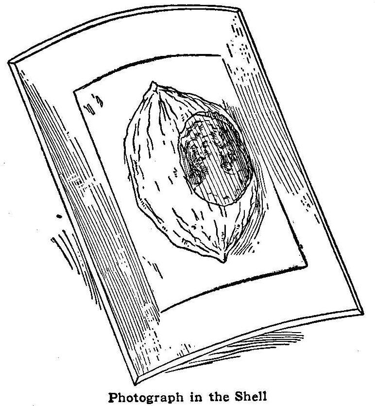
Photograph in the Shell
Split an English walnut in the center, remove the contents, and
scrape out the rough parts. Make an oval opening by filing or
grinding. If a file is used, it should be new and sharp. After
this is done, take a small half round file and smooth the edges
into shape and good form.
The photograph print should be quite small—less than 1/2 in.
across the face. Trim the print to a size a little larger than
the opening in the shell, and secure it in place with glue or
paste. It may be well to fill the shell with cotton. Mount the
shell on a small card with glue, or if desired, a mount of
different shape can be made of burnt woodwork.
Contributed by C. S. Bourne, Lowell, Mass.
Spoon Holder on a Kettle
Spoon Holder
In making marmalade and jellies the ingredients must be stirred
from time to time as the cooking proceeds. After stirring, some
of the mixture always remains on the spoon. Cooks often lay the
spoon on a plate or stand it against the cooking utensil with the
handle down. Both of these methods are wasteful. The accompanying
illustration shows a device made of sheet copper to hold the
spoon so that the drippings will return to the cooking utensil.
The copper is not hard to bend and it can be shaped so that the
device can be used on any pot or kettle.
Contributed by Edwin Marshall, Oak Park, Ill.
Repairing Cracked Gramophone Records
Some time ago I received two gramophone records that were cracked
in shipment but the parts were held together with the paper
label. As these were single-faced disk records, I used the
following method to stick them together: I covered the back of
one with shellac and laid the two back to back centering the
holes with the crack in one running at right angles to the crack
in the other. These were placed on a flat surface and a weight
set on them. After several hours’ drying, I cleaned the surplus
shellac out of the holes and played them.
As the needle passed over the cracks the noise was hardly
audible. These records have been played for a year and they sound
almost as good as new.
Contributed by Marion P. Wheeler, Greenleaf, Oregon.
New Use for a Vacuum Cleaner
An amateur mechanic who had been much annoyed by the insects
which were attracted to his electric lights found a solution in
the pneumatic moth trap described in a recent issue of Popular
Mechanics. He fixed a funnel to the end of the intake tube of a
vacuum cleaner and hung it under a globe. The insects came to the
light, circled over the funnel and disappeared. He captured
several pounds in a few hours.
Contributed by Geo. F. Turl, Canton, Ill.
Filtering with a Small Funnel
In filtering a large amount of solution one usually desires
some means other than a large funnel and something to make the
watching of the process unnecessary. If a considerable quantity
of a solution be placed in a large bottle or flask, and a cork
with a small hole in it inserted in the mouth, and the apparatus
suspended in an inverted position over a small funnel so that the
opening of the cork is just below the water level in the funnel,
the filtering process goes on continuously with no overflow of
the funnel.
As soon as the solution in the funnel is below the cork, air is
let into the flask and a small quantity of new solution is let
down into the funnel. The process works well and needs no
watching, and instead of the filtrate being in a large filter
paper, it is on one small piece and can be handled with ease.
Contributed by Loren Ward, Des Moines, Iowa.
A Postcard Rack
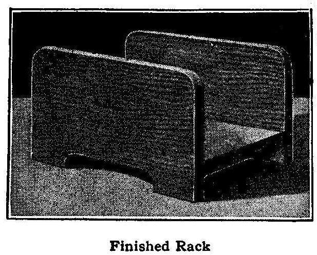
Finished Rack
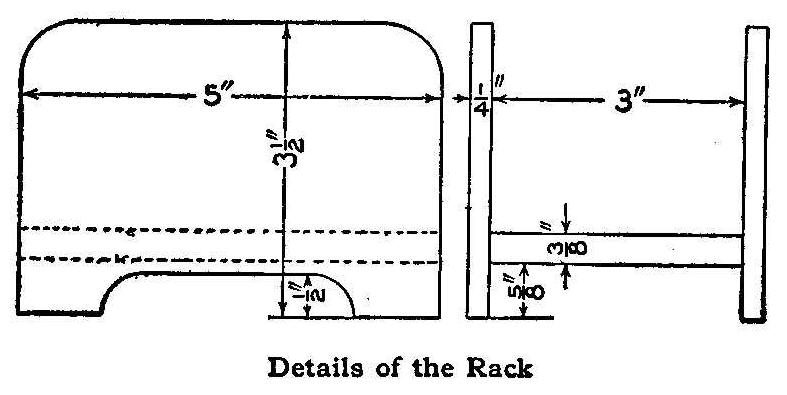
Details of the Rack
The illustration shows a rack for postcards. Those having houses
with mission-style furniture can make such a rack of the same
material as the desk, table or room furnishings and finish it in
the same manner.
The dimensions are given in the detail sketch. The two ends are
cut from 1/4-in. material, the bottom being 3/8 in. thick. Only
three pieces are required, and as they are simple in design,
anyone can cut them out with a saw, plane and pocket knife.
Contributed by Wm. Rosenberg, Worcester, Mass.
Substitute Shoe Horn
A good substitute for a shoe horn is a handkerchief or any piece of
cloth used in the following way: Allow part of the handkerchief
or cloth to enter the shoe, place the toe of the foot in the shoe
so as to hold down the cloth, and by pulling up on the cloth so
as to keep it taut around the heel the foot will slide into the
shoe just as easily as if a shoe horn were used.
Contributed by Thomas E. Dobbins, Glenbrook, Conn.
Building a Small Photographic Dark Room
In building a photographic dark room, it is necessary to make it
perfectly light-tight, the best material to use being matched
boards. These boards are tongued and grooved and when put
together effectually prevent the entrance of light.
The next important thing to be considered is to make it
weather-tight, and as far as the sides are concerned the matched
boards will do this also, but it is necessary to cover the roof
with felt or water-proof paper.
The best thickness for the boards is 1 in., but for cheapness 3/4
in. will do as well, yet the saving is so little that the 1-in.
boards are preferable.
The dark room shown in the accompanying sketch measures 3 ft. 6
in. by 2 ft. 6 in., the height to the eaves being 6 ft. Form the
two sides shown in Fig 1, fixing the crosspieces which hold the
boards together in such positions that the bottom one will act as
a bearer for the floor, and the second one for the developing
bench. Both sides can be put together in this way, and both
exactly alike. Keep the ends of the crosspieces back from the
edges of the boards far enough to allow the end boards to fit in
against them.
One of the narrow sides can be formed in the same way, fixing the
crosspieces on to correspond, and then these three pieces can be
fastened together by screwing the two wide sides on the narrow
one.
Lay the floor next, screwing or nailing the boards to the
crosspieces, and making the last board come even with the ends of
the crosspieces, not even with the boards themselves. The single
boards can then be fixed, one on each side of what will be the
doorway, by screwing to the floor, and to the outside board of
the sides. At the top of the doorway, fix a narrow piece between
the side boards, thus leaving a rectangular opening for the door.
The roof boards may next be put on, nailing them to each other at
the ridge, and to the sides of the room at the outsides and
eaves. They should overhang at the sides and eaves about 2 in.,
as shown in Figs. 3 and 4.
One of the sides with the crosspieces in place will be as shown
in Fig. 2 in section, all the crosspieces and bearers
intersecting around the room.
The door is made of the same kind of boards held together with
crosspieces, one of which is fastened so as to fit closely to the
floor when the door is hinged, and act as a trap for the light.
The top crosspiece is also fastened within 1 in. of the top of
the door for the same reason.
Light traps are necessary at the sides and top of the door. That
at the hinged side can be as shown at A, Fig. 5, the closing side
as at B, and the top as at C in the same drawing. These are all
in section and are self-explanatory. In hinging the door, three
butt hinges should be used so as to keep the joint close.
The fittings of the room are as shown sectionally in Fig. 6, but
before fixing these it is best to line the room with heavy, brown
wrapping paper, as an additional safeguard against the entrance
of light.
The developing bench is 18 in. wide, and in the middle an
opening, 9 by 11 in., is cut, below which is fixed the sink. It
is shown in detail in Fig. 7, and should be zinc
lined.
The zinc should not be cut but folded as shown in Fig. 8, so that
it will fit inside the sink. The bench at each side of the sink
should be fluted (Fig. 9), so that the water will drain off into
the sink. A strip should be fixed along the back of the bench as
shown in Figs. 6 and 9, and an arrangement of slats (Fig. 10),
hinged to it, so as to drop on the sink as in Fig. 6, and shown
to a larger scale in Fig. 11.
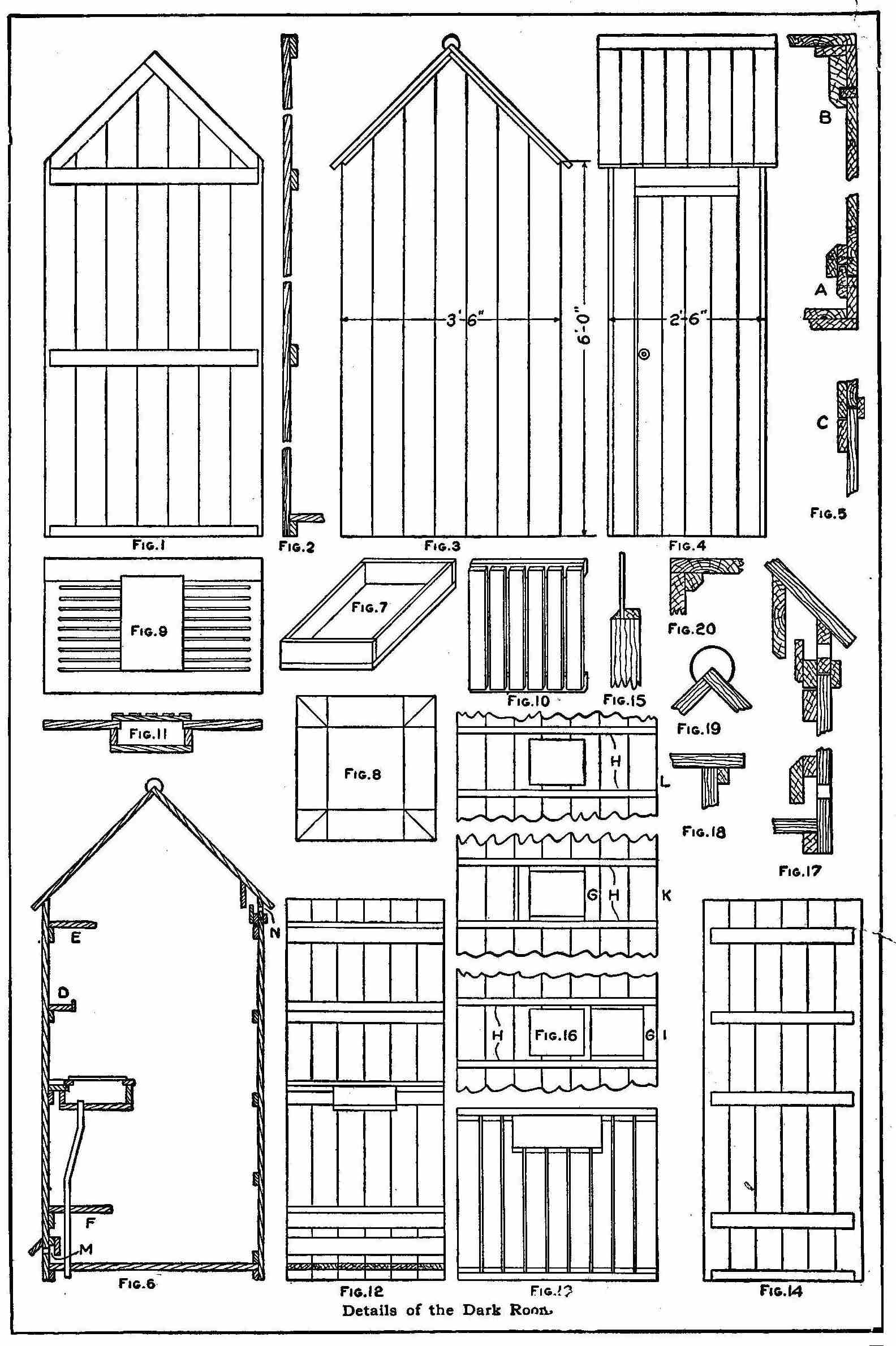
Details of the Dark Room
A shelf for bottles and another for plates, etc., can be fixed
above the developing bench as at D and E (Fig. 6) and another as
F in the same drawing. This latter forms the bottom of the tray
rack, which is fixed on as shown in Fig. 13. The divisions of the
tray rack are best fitted loosely in grooves formed by fixing
strips to the shelves and under the bench and sink as in Fig. 13.
Extra bearing pieces will be wanted for the shelves mentioned
above, these being shown in Fig. 14. The window is formed by
cutting an opening in the side opposite the door, and fixing in
it a square of white glass with strips of wood on the inside and
putty on the outside, as in Fig. 15. A ruby glass is framed as
shown at G, Fig. 16, and arranged to slide to and fro in the
grooved runners H, which makes it possible to have white light,
as at I, or red light as at K, Fig. 16. The white glass with
runners in position is shown at L in the same drawing, but not
the red glass and frame. Ventilation is arranged for by boring a
series of holes near the floor, as at M, Fig. 6, and near the
roof as at N in the same drawing, and trapping the light without
stopping the passage of air, as shown in the sections, Fig. 17.
The finish of the roof at the gables is shown in Fig. 18, the
strip under the boards holding the felt in position when folded
under, and the same is true of the roll at the top of the roof in
Fig. 19.
The house will be much strengthened if strips, as shown in Fig.
20, are fastened in the corners inside, after lining with brown
paper, screwing them each way into the boards.
The door may have a latch or lock with a knob, but should in
addition have two buttons on the inside, fixed so as to pull it
shut tightly at top and bottom. A waste pipe should be attached
to the sink and arranged to discharge through the floor. A
cistern with pipe and tap can be fastened in the top of the dark
room, if desired, or the room may be made with a flat roof, and a
tank stand on it, though this is hardly advisable.
It is absolutely necessary that the room be well painted, four
coats at first is not too many, and one coat twice a year will
keep it in good condition.
A brick foundation should be laid so that no part of the room
touches the ground.
The Versatile Querl
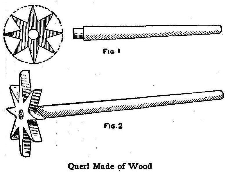
Querl Made of Wood
“Querl” is the German name for a kitchen utensil which may be
used as an egg-beater, potato-masher or a lemon-squeezer. For
beating up an egg in a glass, mixing flour and water, or stirring
cocoa or chocolate, it is better than anything on the market.
This utensil is made of hardwood, preferably maple or ash. A
circular piece about 2 in. in diameter is cut from 1/2-in. stock
and shaped like a star as shown in Fig. 1, and a 3/8-in. hole
bored in the center for a handle. The handle should be at least
12 in. in length and fastened in the star as shown in Fig. 2.
In use, the star is placed in the dish containing the material to
be beaten or mixed and the handle is rapidly rolled between the
palms of the hands.
Contributed by W. Karl Hilbrich, Erie, Pennsylvania.
An Emergency Soldering Tool
Occasionally one finds a piece of soldering to do which is
impossible to reach with even the smallest of the ordinary
soldering irons or coppers. If a length of copper wire as large
as the job will permit and sufficiently long to admit being bent
at one end to form a rough handle, and filed or dressed to a
point on the other, is heated and tinned exactly as a regular
copper should be, the work will cause no trouble on account of
inaccessibility.
Contributed by E. G. Smith, Eureka Springs, Ark.
Smoothing Paper after Erasing
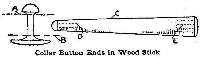
Collar Button Ends In Wood Stick
When an ink line is erased the roughened surface of the paper
should be smoothed or polished so as to prevent the succeeding
lines of ink from spreading. A convenient desk accessory for this
purpose can be made of a short piece of hardwood and two bone
collar buttons.
File off the head of one button at A and the base from another at
B. Bore a small hole D and E in each end of the wood handle C and
fasten the button parts in the holes with glue or sealing wax.
The handle can be left the shape shown or tapered as desired. The
small end is used for smoothing small erasures and the other end
for larger surfaces.
A Cherry Seeder
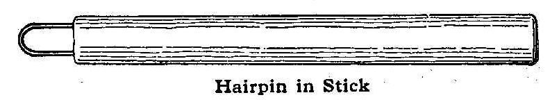
Hairpin In Stick
An ordinary hairpin is driven part way into a small round piece
of wood, about 3/8 in. in diameter and 2 or 2-1/2 in. long, for a
handle, as shown in the sketch. The hairpin should be a very
small size. To operate, simply insert the wire loop into the
cherry where the stem has been pulled off and lift out the seed.
Contributed by L. L. Schweiger, Kansas City, Mo.
A Dovetail Joint
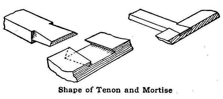
Shape of Tenon and Mortise
The illustration shows an unusual dovetail joint, which, when put
together properly is a puzzle. The tenon or tongue of the joint
is sloping on three surfaces and the mortise is cut sloping to
match. The bottom surface of the mortise is the same width at
both ends, the top being tapering toward the base of the tongue.
Contributed by Wm. D. Mitchell, Yonkers, New York.
Base for Round-End Bottles
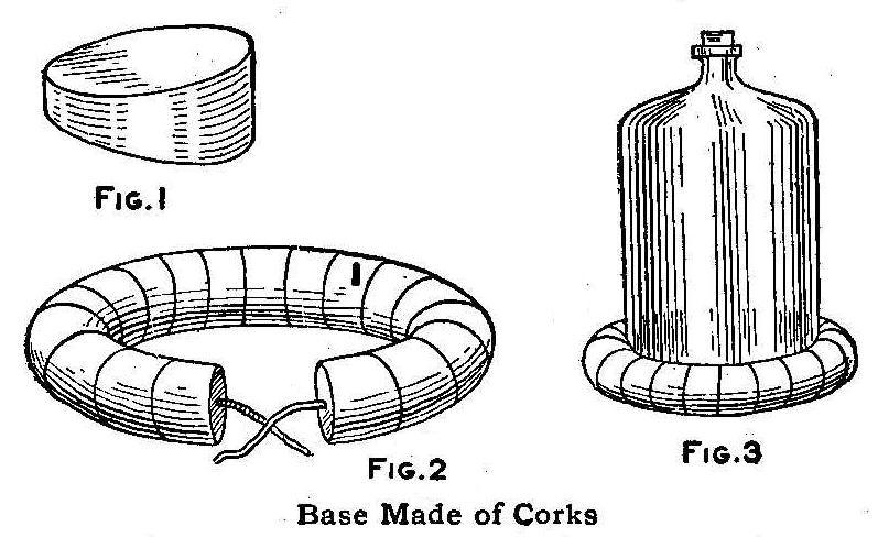
Base Made of Corks
The many forms of round-bottomed glass bottles used in chemical
laboratories require some special kind of support on which they
can be safely placed from time to time when the chemist does not,
for the moment, need them. These supports should not be made of
any hard material nor should they be good conductors of heat, as
such qualities would result in frequent breakage.
A French magazine suggests making the supports from the large
corks of glass jars in which crystal chemicals are usually
supplied from the dealers. The manner of making them is clearly
shown in the sketch. Each cork is cut as in Fig. 1 and placed on
a wire ring (Fig. 2) whose ends are twisted together and the last
section of cork is cut through from the inner side to the center
and thus fitted over the wire covering the twisted ends, which
binds them together. The corks in use are shown in Fig. 3.
Rustic Window Boxes
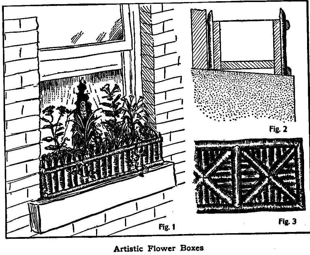
Artistic Flower Boxes
Instead of using an ordinary green-painted window box, why not
make an artistic one in which the color does not clash with the
plants contained in it but rather harmonizes with them.
Such a window box can be made by anyone having usual mechanical
ability, and will furnish more opportunities for artistic and
original design than many other articles of more complicated
construction.
The box proper should be made a little shorter than the length of
the window to allow for the extra space taken up in trimming and
should be nearly equal in width to the sill, as shown in Fig. 1.
If the sill is inclined, as is usually the case, the box will
require a greater height in front, to make it set level, as shown
in Fig. 2.
The box should be well nailed or screwed together and should then
be painted all over to make it more durable. A number of 1/2-in.
holes should be drilled in the bottom, to allow the excess water
to run out and thus prevent rotting of the plants and box.
Having completed the bare box, it may be trimmed to suit the
fancy of the maker. The design shown in Fig. 1 is very simple and
easy to construct, but may be replaced with a panel or other
design. One form of panel design is shown in Fig. 3.
Trimming having too rough a surface will be found unsuitable for
this work as it is difficult to fasten and cannot be split as
well as smooth trimming. It should be cut the proper length
before being split and should be fastened with brads. The
half-round hoops of barrels will be found very useful in
trimming, especially for filling-in purposes, and by using them
the operation of splitting is avoided. After the box is trimmed,
the rustic work should be varnished, in order to thoroughly
preserve it, as well as improve its appearance.
Antidote for Squirrel Pest
To the owner of a garden in a town where squirrels are protected
by law, life in the summer time is a vexation. First the
squirrels dig up the sweet corn and two or three replantings are
necessary. When the corn is within two or three days of being
suitable for cooking, the squirrels come in droves from far and
near. They eat all they can and carry away the rest. When the
corn is gone cucumbers, cabbages, etc., share the same fate,
being partly eaten into. At the risk of being arrested for
killing the squirrels I have used a small target rifle morning
and night, but during my absence the devastation went on
steadily. Last year they destroyed my entire corn crop. Traps do
no good; can’t use poison, too dangerous. But I have solved the
difficulty; it’s easy.
Shake cayenne pepper over the various vegetables which are being
ruined, and observe results.
Homemade Electric Stove
By J. F. Tholl
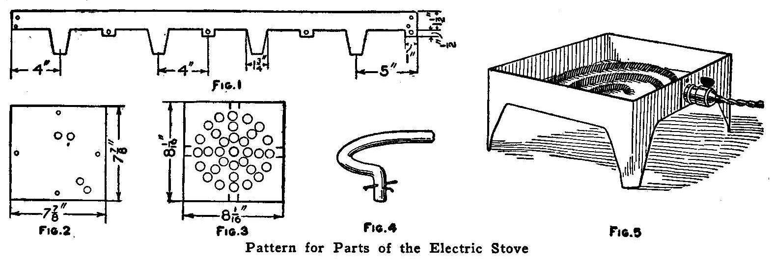
Pattern for Parts of the Electric Stove
The construction of an electric stove is very simple, and it can
be made by any home mechanic having a vise and hand drill. The
body is made of sheet or galvanized iron, cut out and drilled as
shown in Fig. 1.
Each long projection represents a leg, which is bent at right
angles on the center line by placing the metal in the jaws of a
vise and hammering the metal over flat. If just the rim is
gripped in the vise, it will give a rounding form to the lower
part of the legs. The small projections are bent in to form a
support for the bottom.
The bottom consists of a square piece of metal, as shown in Fig.
2. Holes are drilled near the edges for stove bolts to fasten it
to the bottom projections. Two of the larger holes are used for
the ends of the coiled rod and the other two for the heating-wire
terminals. The latter holes should be well insulated with
porcelain or mica. The top consists of a square piece of metal
drilled as shown in Fig. 3. Four small ears are turned down to
hold the top in place.
One end of the coiled rod is shown in Fig. 4. This illustrates
how two pins are inserted in holes, drilled at right angles, to
hold the coil on the bottom plate. The coiled rod is 3/16 in. in
diameter and 27 in. long. The rod is wrapped with sheet
asbestos, cut in 1/2-in. strips.
The length of the heating wire must be determined by a test. This
wire can be purchased from electrical stores. Stovepipe wire will
answer the purpose when regular heating wire cannot be obtained.
The wire is coiled around the
asbestos-covered rod, so that no
coil will be in contact with another coil. If, by trial, the coil
does not heat sufficiently, cut some of it off and try again.
About 9-1/2 ft. of No. 26 gauge heating wire will be about right.
The connection to an electric-lamp socket is made with ordinary
flexible cord, to which is attached a screw plug for making
connections.
Glass-Cleaning Solution
Glass tumblers, tubing and fancy bottles are hard to clean by
washing them in the ordinary way, as the parts are hard to reach
with the fingers or a brush. The following solution makes an
excellent cleaner that will remove dirt and grease from crevices
and sharp corners. To 9 parts of water add 1 part of strong
sulphuric acid.
The acid should be added to the water slowly and
not the water to the acid. Add as much bichromate of potash as
the solution will dissolve. More bichromate of potash should be
added as the precipitate is used in cleaning.
The chemicals can be purchased cheaply from a local drug store,
and made up and kept in large bottles. The solution can be used
over and over again.
Contributed by Loren Ward Des Moines, Iowa.
Automatic-Closing Kennel Door
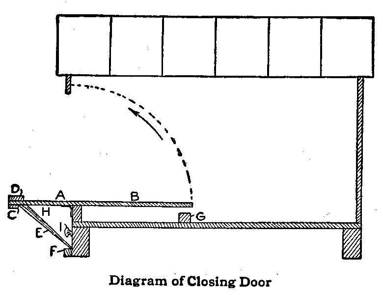
Diagram of Closing Door
When the neighborhood cats are retired for the night and there is
nothing more to chase, my fox terrier seems to realize that his
usefulness for the day is over and begs to be put in his kennel
that he may not bark at the moon as some dogs are apt to do. This
necessitates my putting him out at a time when it may not be
convenient. Frequently in stormy weather this is a disagreeable
duty and I found a way to obviate it by making a trapdoor device
for his kennel as shown in the sketch whereby he may lock himself
in when he crosses the threshold.
The outer half A of the hinged trapdoor is made heavier than the
inner half B by a cleat, C, and a strip, D, to cause the door to
swing shut. The tripper stick E is set between cleats C and F to
hold the door open. When the dog steps on the inner half of the
trapdoor B, it falls to stop G, releasing tripper stick E (which
is heavier on the top end H) to cause it to fall clear of the
path of the trapdoor. The door then swings shut in the direction
of the arrow, the latch I engaging a slot in the door as it
closes, and the dog has locked himself in for the night. The
latch I is made of an old-fashioned gate latch which is mortised
in the bottom joist of the kennel. When releasing the dog in the
morning the door is set for the evening.
Contributed by Victor Labadie, Dallas, Texas.
Polishing Cloths for Silver
Mix 2 lb. of whiting and 1/2 oz. of oleic acid with 1 gal. of
gasoline. Stir and mix thoroughly. Soak pieces of gray outing
flannel of the desired size—15 by 12 in. is a good size—in this
compound. Wring the surplus fluid out and hang them up to dry,
being careful to keep them away from the fire or an open flame.
These cloths will speedily clean silver or plated ware and will
not soil the hands.
In cleaning silver, it is best to wash it first in hot water and
white soap and then use the polishing cloths. The cloths can be
used until they are worn to shreds. Do not wash them. Knives,
forks, spoons and other small pieces of silver will keep bright
and free from tarnish if they are slipped into cases made from
the gray outing flannel and treated with the compound. Separate
bags for such pieces as the teapot, coffee pot, hot-water pot,
cake basket and other large pieces of silverware will keep them
bright and shining.
Contributed by Katharine D. Morse, Syracuse, N. Y.
A Book-Holder
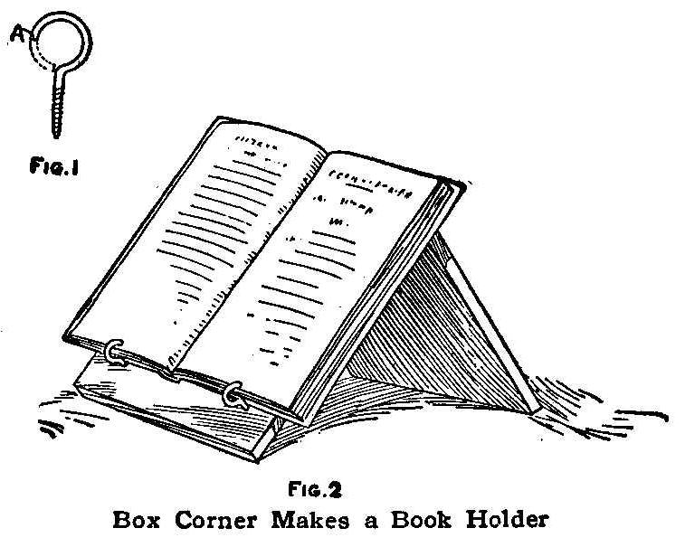
Fig 2. Box Corner Makes a Book Holder
Books having a flexible back are difficult to hold in an upright
position when copying from them. A makeshift combination of
paperweights and other books is often used, but with
unsatisfactory results.
The book-holder shown in the sketch will hold such books
securely, allow the pages to be turned easily and conceal the
smallest possible portion of each page.
The holder can be cut out of a box corner and fitted with two
screw eyes, which have the part shown by the dotted lines at A
(Fig. 1) removed. The length of the back board determines the
slope for the book rest.
Contributed by James M. Kane, Doylestown, Pa.
Clamping a Cork
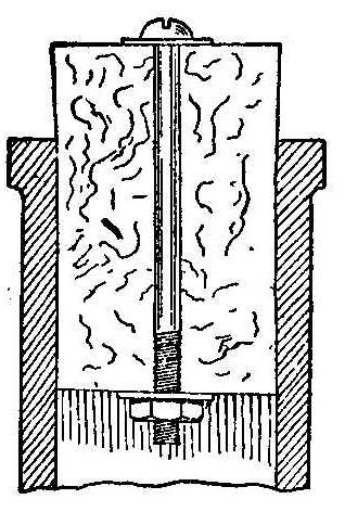
It is aggravating to continually break the cork of the stock
mucilage bottle because of its sticking to the neck of the bottle
after a supply has been poured out. If a stove bolt is inserted
lengthwise through the cork with a washer on each end and the nut
screwed up tightly, as shown in the sketch, the cork may be made
to last longer than the supply of mucilage and can be placed in a
new bottle and used over and over again.
Withdrawing Paper from under an Inverted Bottle
Invert a bottle on a piece of paper near the edge of a table top
and ask anyone to remove the paper without overturning the
bottle. They will at once jerk the paper with the result that the
bottle will turn over. To remove the paper just strike the table
top with your right fist while pulling the paper slowly with your
left hand. As you strike the table the bottle will jump and
release the paper.
Contributed by Maurice Baudier, New Orleans, La.
Emergency Tire Repair
A bone collar button makes a good substitute for a plug in
repairing a puncture in a single-tube bicycle tire.
Broom Holder Made of a Hinge
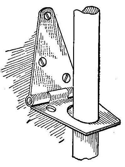
The broom holder shown in the sketch is made of an ordinary hinge
with one wing screwed to the wall. The loose wing has a large
hole drilled in it to receive the handle of the broom. The manner
of holding the broom is plainly shown in the sketch.
Contributed by Theodore L. Fisher; Waverly, Ill.
Making Proofs before the Negative Dries
A correspondent of Camera Craft makes proofs from his developed,
but unfixed, negatives, by squeezing a sheet of wet bromide paper
into contact with the wet film and giving an exposure several
times longer than would be required under ordinary conditions,
using the paper dry. If the developer is well rinsed out of the
film, the exposure to artificial light necessary to make a print
will have no injurious effect upon the negative, which is, of
course, later fixed and washed as usual.
Flower-Pot Stand
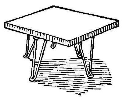
A very useful stand for flower pots can be made of a piece of
board supported by four clothes hooks. The top may be of any size
suitable for the flower pot. The hooks which serve as legs are
fastened to the under side of the board in the same manner as
fastening the hook to a wall.
Contributed by Oliver S. Sprout, Harrisburg, Pa.
A Line Harmonograph
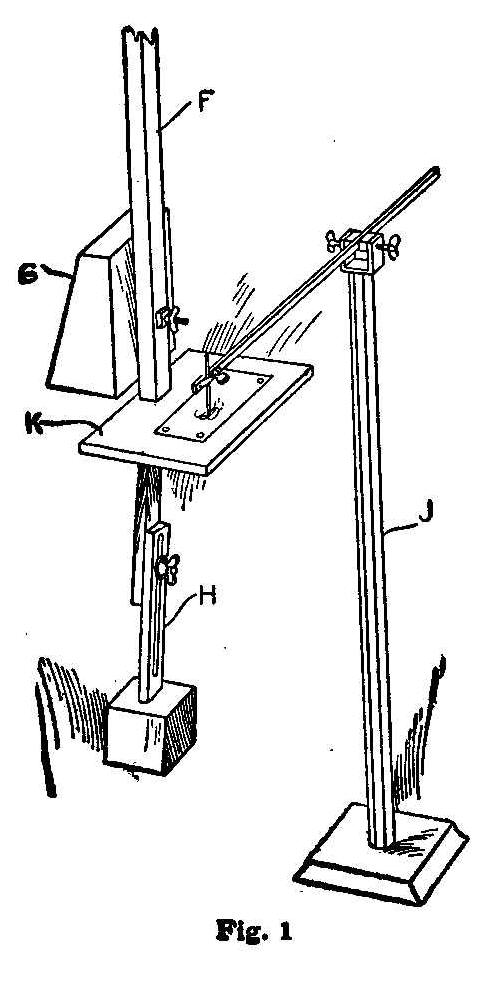
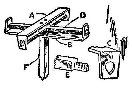
As an apparatus capable of exciting interest, probably nothing so
easily constructed surpasses the harmonograph. Your attention
will be completely absorbed in the ever changing, graceful sweep
of the long pendulum, the gyrations of which are faithfully
recorded in the resulting harmonogram.
A careless impetus given to the pendulum may result in a very
beautiful harmonogram, but you may try innumerable times to
duplicate this chance record without success. No two hamonograms
are exactly alike. The harmonograph, while its pendulum swings in
accordance with well known natural laws, is exceedingly erratic
when it comes to obeying any preconceived calculations of its
operator. In this uncertainty lies the charm. If time hangs
heavily or a person is slightly nervous or uneasy, a harmonograph
is a good prescription.
The prime essential in a well working harmonograph is a properly
constructed universal joint. Where such a joint is made with
pivots for its bearings, one pair of pivots are very liable to
have more friction than the other, which retards the movement and
causes the harmonograph to undergo a continuous change of axis.
To obviate this difficulty, the joint should be made similar to
those used on scales. The general appearance of such a joint is
shown in the first illustration, Fig. 1. Stirrups A and B are
made of 7/8 by 1/4-in. metal. Holes are drilled in each end of
these stirrups and filed out as shown at C. The two holes shown
in the center of the stirrup A are drilled to fasten the
apparatus to the ceiling. Two corresponding holes are drilled in
B to fasten the long pendulum F to the joint. The cross of the
joint D has the ends shaped as shown at E. The rounded shoulder
on E is to prevent the cross from becoming displaced by a jar or
accident. The ends of the cross are inserted through the holes C
of the stirrups, then slipped back so the knife edges engage in
the V-shaped holes of the stirrups. The cross must be so made
that the knife edges will be in the same plane. This can be
determined by placing two of the knife edges on the jaws of a
vise and then laying two rules across the other two edges. The
rules should just touch the jaws of the vise and the two knife
edges of the cross. This makes a universal joint almost free from
friction and, what is most important, prevents the pendulum from
twisting on its own axis.
The pendulum F should be made of ash or oak, 1-3/4 by 2 in., with
a length depending on the height of the ceiling. A length of 7
ft. is about right for a 10-ft. ceiling.
A small table or platform, K, as shown in the lower part of Fig.
1, is fastened to the lower end of the pendulum as a support for
the cards on which harmonograms are made. A weight, G, of about
30 or 40 lb.-a box filled with small weights will do—is attached
to the pendulum just above the table. Another weight of about 10
lb. is attached as shown at H. A pedestal, J, provides a means of
support for the stylus. The stylus arm should have pin-point
bearings, to prevent any side motion.
The length of the short pendulum H, which can be regulated, as
shown in Fig. 1, should bear a certain and exactly fixed relation
to the length of the main pendulum, for the swinging times of
pendulums are inversely proportionate to their lengths, and
unless the shorter pendulum is, for instance, exactly one-third,
one-fourth, one-fifth, etc., as long as the other, that is, makes
respectively 3, 4 or 5 swings to one swing of the long pendulum,
they will not harmonize and a perfect harmonogram is not
obtained.

Lines Made with the Harmonograph
A good stylus to contain the ink is easily made from a glass tube
1/4 in. in diameter. Heat the tube in an alcohol or Bunsen flame
and then, by drawing the two portions apart and twisting at the
same time, the tube may be drawn to a sharp point. An opening of
any desired size is made in the point by rubbing it on a
whetstone. Owing to the fact that the style of universal joint
described has so little friction, the stylus point must be very
fine, or the lines will overlap and blur. A small weight, such as
a shoe buttoner, placed on the arm near the stylus will cause
enough friction to make the pendulum “die” faster and thus remedy
the trouble.
Contributed by Wm. R. Ingham, Rosemont, Arizona.
Cutting Circular Holes in Thin Sheet Metal
In arts and crafts work, occasion often arises to cut a perfectly
circular hole in sheet copper or brass. To saw and file it out
takes time and skill. Holes up to 3 in. in diameter can be cut
quickly and accurately with an ordinary expansive bit.
Fasten the sheet metal to a block of wood with handscrews or a
vise. Punch a hole, with a nail set or punch, in the center of
the circle to be cut, large enough to receive the spur of the
expansive bit. A few turns of the brace will cut out the circle
and leave a smooth edge.
Contributed by James T. Gaffney, Chicago.
Key Card for Writing Unreadable Post Cards
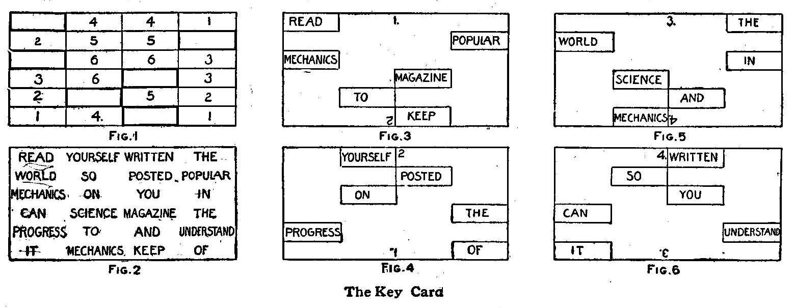
The Key Card
A key card for use in correspondence on postals that makes the
matter unreadable unless the recipient has a duplicate key card
is made as follows: Rule two cards the size of postal, one for
the sender and one for the receiver, dividing them into quarters.
These quarters are subsequently divided into any convenient
number of rectangular parts-six in this case.
These parts are numbered from one to six in each quarter
beginning at the outside corners and following in the same order
in each quarter. Cut out one rectangle of each number with a
sharp knife, distributing them over the whole card. Then put a
prominent figure 1 at the top of one side, 2 at the bottom and 3
and 4 on the other side. The numbering and the cutouts are
shown in Fig. 1. The two key cards are made alike.
The key card is used by placing it over a postal with the figure
1 at the top and writing in the spaces from left to right as
usual, Fig. 3, then put 2 at the top, Fig. 4, and proceed as
before, then 3 as in Fig. 5, and 4 as in Fig. 6. The result will
be a jumble of words as shown in Fig. 2, which cannot be read to
make any sense except by use of a key card.
Contributed by W.J. Morey, Chicago.
Homemade Carpenter’s Vise
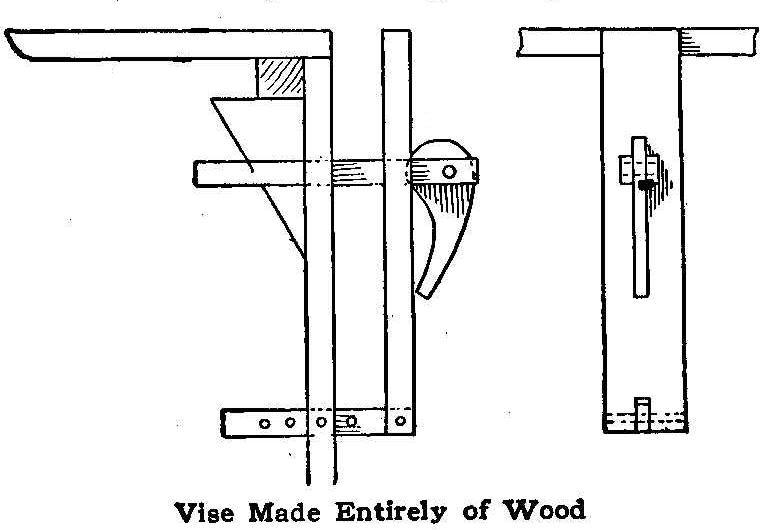
The sketch shows an easily made, quick-working wood vise that has
proved very satisfactory. The usual screw is replaced by an open
bar held on one end by a wedge-shaped block, and the excess
taken up on the other end by an eccentric lever. The wedge is
worked by a string passing through the top of the bench and
should be weighted on the other end to facilitate the automatic
downward movement. The capacity of the vise, of course, depends
on the size and shape of the wedge-shaped block.
Contributed by J.H. Cruger, Cape May City, N.J.
Toning Blue on Bromide and Platinum
After some experimenting to secure a blue tone on bromide prints,
a correspondent of the Photographic Times produced a very
pleasing bluish green tint by immersing the prints in a solution
composed of 30 gr. of ferricyanide of potash,
30 gr. citrate of
iron and ammonia, 1/2 oz. acetic acid and 4 oz. of water. After
securing the tint desired, remove the prints, rinse them in clean
water for a few minutes, and then place them in a dilute solution
of hydrochloric acid.
Wash the prints thoroughly and hang them up with clips to dry.
Cutting Loaf Bread
When cutting a loaf of bread do not slice it from the outer
crusted end. Cut through the center, then cut slices from the
center toward the ends. The two cut surfaces can be placed
together, thus excluding the air and keeping the bread fresh as
long as there is any left to slice.
Contributed by L. Alberta Norrell, Augusta, Ga.
How to Make an Electric Toaster
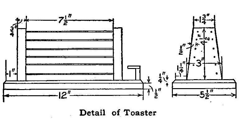
Detail of Toaster
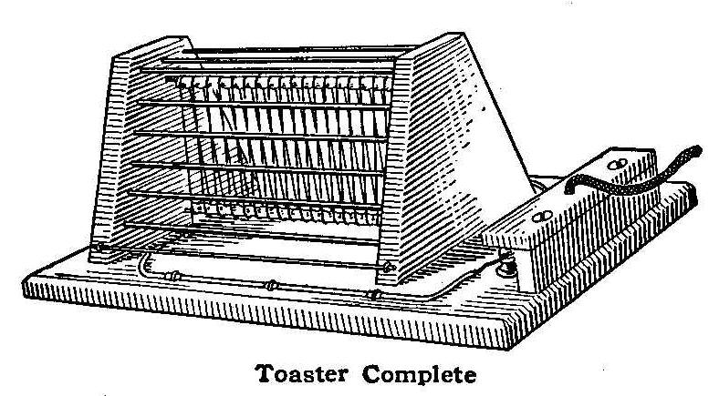
Toaster Complete
The electric toaster shown in the sketch is not hard to make. The
framework comprising the base and the two uprights may be made
either of hardwood or asbestos board,
says Popular Electricity.
If constructed of the former, the portion of the base under the
coil, and the inside surfaces of the two uprights should be
covered with a 1/8-in. sheet of well made
asbestos paper, or thin
asbestos board may be substituted for this lining.
Asbestos board
is to be preferred, and this material in almost any degree of
hardness may be purchased. It can be worked into shape and will
hold wood screws. The detail drawing gives all dimensions
necessary to shape the wood or asbestos board.
After preparing the base and uprights, drill 15 holes, 1/4 in.
deep, into the inside face of each upright to support the No. 6
gauge wires shown. The wires at the top and bottom for holding
the resistance wire are covered with
asbestos paper and the holes
for these wires are 3/4 in. from the top and bottom,
respectively, of the uprights. The wires that form the cage about
the heater coil and are used for a support for the toast are 15
pieces of No. 6 gauge iron wire each 8 in. long. The screws that
hold the uprights in position should have the heads countersunk
on the under side of the base. The binding-posts should now be
set in position and their protecting covering containing the
reinforced cord left until the other parts are finished.
To assemble, secure one upright in position using 1-1/2 in.
wood-screws. Place the other upright where it belongs without
fastening it and put the stretcher wires for holding the
resistance wire in place. Put the
asbestos paper on these and
with the assistance of a helper begin winding on the heater coil.
Use 80 ft. of 18-per-cent No. 22 gauge German-silver wire. Wind
the successive turns of wire so they will not touch each other
and fasten at each end with a turn or two of No. 16 gauge copper
wire. When this is complete have the helper hold the stretcher
wires while you tip the unfastened upright out and insert the
wires of the cage, then fasten the upright in place.
The wire from the binding-posts to the coil may be what is known
underwriters’ wire or
asbestos-covered wire No. 14 gauge, which
is held in place by double-headed tacks containing an insulation
at the head. These may be procured from electrical supply
houses. Connect the reinforced cord and terminals to the binding
screws and fasten the cover in place. This toaster will take four
amperes on [a] 110-volt circuit.
Cabinet for the Amateur’s Workshop
Empty Cigar Boxes Used for Drawers
One of the most convenient adjuncts to an amateur’s workbench is
a cabinet of some sort in which to keep nails, rivets, screws,
etc., instead of leaving them scattered all about the bench. A
very easily made cabinet for this purpose is shown in the
accompanying illustration. The case may be made of 1/2-in. white
pine or white wood of a suitable size to hold the required number
of drawers which slide on strips of the same material, cut and
dressed 1/2 in. square. The drawers are made of empty cigar boxes
of uniform size, which, if one is not a smoker, may be readily
obtained from any cigar dealer, as they are usually thrown away
when empty.
Small knobs may be added if desired, but these are not necessary,
as the spaces shown between the drawers give ample room to grasp
them with the fingers. Labels of some kind are needed, and one of
the neatest things for this purpose is the embossed aluminum
label, such as is stamped by the well known penny-in-the-slot
machines to be found in many railroad stations and amusement
places.
Contributed by Frederick E. Ward, Ampere, N. Y.
Uncurling Photographs
Photograph prints can be kept from curling when dry, by giving
them the same treatment as was once used on films. Immerse for 5
minutes in a bath made by adding 1/4 oz. of glycerine to 16 oz. of
water.
Soldering for the Amateur
Successful soldering will present no serious difficulties to
anyone who will follow a few simple directions. Certain metals
are easier to join with solder than others and some cannot be
soldered at all. Copper, brass, zinc, tin,
lead, galvanized iron,
gold and silver or any combination of these metals can be easily
soldered, while iron and aluminum are common metals that cannot
be soldered.
It is necessary to possess a soldering copper, a piece of solder,
tinner’s acid, sandpaper or steel wool, a small file and a piece
of sal ammoniac. If the soldering copper is an old one, or has
become corroded, it must be ground or filed to a point. Heat it
until hot (not red hot), melt a little solder on the sal
ammoniac, and rub the point of the copper on it, turning the
copper over to thoroughly tin the point on each face. This
process is known as tinning the iron and is very necessary to
successful work.
After the copper is tinned you may place it in the fire again,
being careful about the heat, as too hot an iron will burn off
the tinning.
The parts to be soldered must be thoroughly cleaned by
sandpapering or the use of steel wool until the metal shows up
bright. Then apply the acid only to the parts to be soldered with
a small stiff brush or a small piece of cloth fastened to a
stick, or in a bent piece of tin to form a swab.
Tinner’s acid is made by putting as much zinc in commercial
muriatic acid as will dissolve.
This process is best accomplished
in an open earthenware dish. After the acid has ceased to boil
and becomes cool it may be poured into a wide-mouthed bottle
which has a good top or stopper, and labeled “Poison.”
Place the parts to be soldered in their correct position and
apply the hot copper to the solder, then to the joint to be
soldered, following around with the copper and applying solder as
is necessary.
In joining large pieces it is best to “stick” them together in
several places to hold the work before trying to get all around
them. A little practice will soon teach the requisite amount of
solder and the smoothness required for a good job.
In soldering galvanized iron, the pure muriatic acid should be
used, particularly so when the iron has once been used.
C. G. S., Eureka Springs, Ark.
Washboard Holder
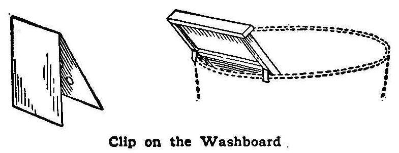
Clip on the Washboard
When using a washboard it will continually slip down in the tub.
This is considerable annoyance, especially if a large tub is
used. The washboard can be kept in place with small metal hooks,
as shown in the sketch. Two of these are fastened to the back of
the washboard in the right place to keep it at the proper slant.
Contributed by W. A. Jaquythe, Richmond, California.
A Mission Bracket Shelf
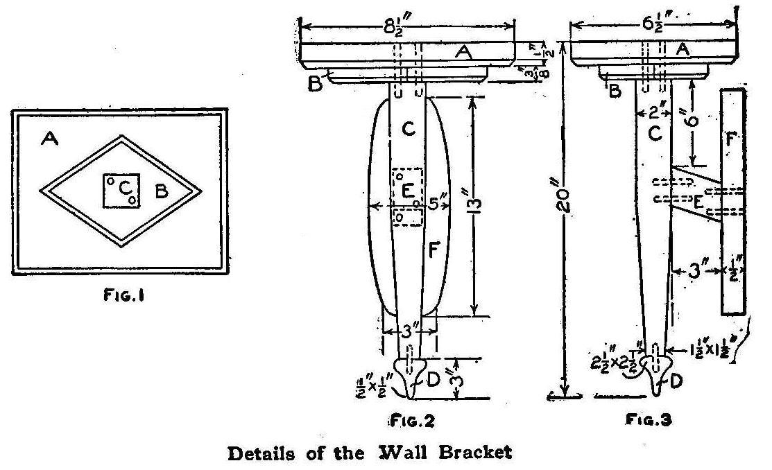
Details of the Wall Bracket
The shelf consists of six pieces of wood A, B, C, D, E and F. The
material can be of any wood. I have one made of mahogany finished
in natural color, and one made of poplar finished black. The
dimensions given in the detail drawings are sufficient for anyone
to make this bracket. The amount of material required is very
small and can be made from scrap, or purchased from a mill
surfaced and sanded. The parts are put together with dowel pins.
Contributed by A. Larson, Kenosha, Wis.
How to Make a Finger Ring
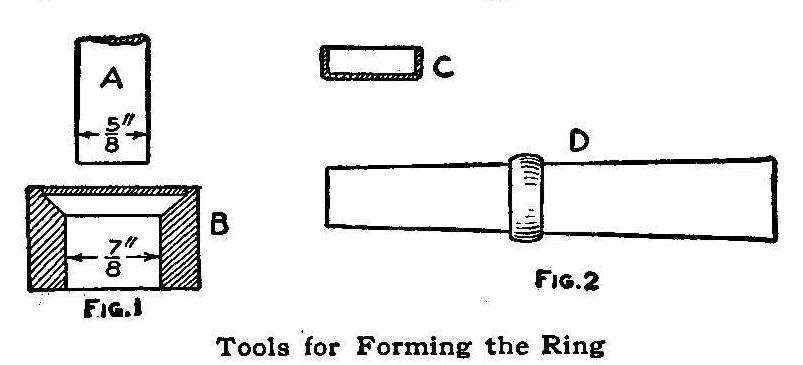
Tools for Forming the Ring
While the wearing of copper rings for rheumatism may be a foolish
notion, yet there is a certain galvanic action set up by the
contact of the acid in the system of the afflicted person with
the metal of the ring. Apart from this, however, a ring may be
made from any metal, such as copper, brass and silver, if such
metals are in plate or sheet form, by the following method:
All the tools necessary are a die and punch which are simple to
make and will form a ring that will fit the average finger. Take
a 3/4-in. nut, B, Fig. 1, and drill out the threads. This will
leave a clear hole, 7/8 in. in diameter, or a hole drilled the
desired size in a piece of iron plate will do as well.
Countersink the top of the hole so that the full diameter of the
countersink will be 1-1/4 in. This completes the die. The punch
A, is made of a piece of 5/8 in. round iron, slightly rounded on
the end so that it will not cut through the metal disk. The
dimensions shown in Fig. 1 can be changed to suit the size of the
finger to be fitted.
{40}
The metal used should be about 1/16 in. thick and 1-1/4 in. in
diameter. Anneal it properly by heating and plunging in water.
Lay it on the die so that it will fit nicely in the countersink
and drive it through the hole by striking the punch with a
hammer. Hold the punch as nearly central as possible when
starting to drive the metal through the hole. The disk will come
out pan shaped, C, and it is only necessary to remove the bottom
of the pan to have a band which will leave a hole 5/8 in. in
diameter and 1-1/4 in. wide. Place the band, D, Fig. 2, on a
stick so that the edges can be filed and rounded to shape. Finish
with fine emery cloth and polish. Brass rings can be plated when
finished.
Contributed by H. W. Hankin, Troy, N. Y.
How to Bind Magazines
A great many readers of Popular Mechanics Magazine save their
copies and have them bound in book form and some keep them
without binding. The bound volumes make an attractive library and
will always be valuable works of reference along mechanical
lines. I bind my magazines at home evenings, with good results.
Six issues make a well proportioned book, which gives two bound
volumes each year.
The covers of the magazines are removed, the wire binders pulled
out with a pair of pliers and the advertising pages removed from
both sides, after which it will be found that the remainder is in
sections, each section containing four double leaves or sixteen
pages. These sections are each removed in turn from the others,
using a pocket knife to separate them if they stick, and each
section is placed as they were in the magazine upon each
preceding one until all six numbers have been prepared. If
started with the January or the July issue, the pages will be
numbered consecutively through the entire pages of the six
issues.
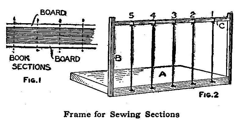
Frame For Sewing Sections
The sections are then prepared for sewing. They are evened up on
the edges by jarring on a flat surface. They are then placed
between two pieces of board and all clamped in a vise. Five cuts,
1/8 in. deep, are made with a saw across the back of the
sections, as shown in Fig. 1. Heavy plain paper is used for the
flyleaves. The paper is cut double the same as the leaves
comprising the sections, making either one or two double sections
for each side as desired.
A frame for sewing will have to be made as shown in Fig. 2 before
the work can be continued on the book. The frame is easily made
of four pieces of wood. The bottom piece A should be a little
larger than the book. The two upright pieces B are nailed to the
outside edge, and a third piece, C, is nailed across the top.
Small nails are driven part way into the base C to correspond to
the saw cuts in the sections. A piece of soft fiber string is
stretched from each nail to the crosspiece C and tied.
Coarse white thread, size 16 or larger, is used for the sewing
material. Start with the front of the book. Be sure that all
sections are in their right places and that the flyleaves are
provided in the front and back. Take the sections of the
flyleaves on top, which should be notched the same as the saw
cuts in the book sections, and place them against the strings in
the frame. Place the left hand on the inside of the leaves where
they are folded and start a blunt needle, threaded double,
through the notch on the left side of the string No. 1 in Fig. 2.
Take hold of the needle with the right hand and pass it to the
left around the string No. 1, then back through the notch on the
right side. Fasten the thread by tying or making a knot in the
end and passing the needle through it. After drawing the thread
tightly, pass the needle through the notch on the left side of
the string No. 2, passing it around the string and tying in the
same manner as for No. 1.
{41}
Each section is fastened to the five
strings in the same manner, the thread being carried across from
each tie from No. 1 to 2 then to 3 and so on until all strings
are tied. The string No. 5 is treated in the same manner only
that the needle is run through on the left side of the string a
second time, leaving the needle on the outside in position for
the next section, which is fastened the same as the first, the
needle being passed through the notch on the right side of the
string No. 5, and then to string No.4, passing around on the
right side and back on the left and so on. Keep the thread drawn
up tightly all the time.
After the sewing is completed cut the strings, allowing about 2
in. of the ends extending on each side. The fibers of these ends
are separated and combed out so that they can be glued to the
covers to serve as a hinge. A piece of cheesecloth is cut to the
size of the back and glued to it. Ordinary liquid glue is the
best adhesive to use.
Procure heavy cardboard for the covers and cut two pieces 1/2 in.
longer and just the same width as the magazine pages. The
covering can be of cloth, leather or paper according to the taste
and resources of the maker. The covering should be cut out 1 in.
larger on all edges than both covers and space on the back. Place
the cardboard covers on the book, allowing a margin of 1/4 in. on
all edges except the back, and measure the distance between the
back edges of the covers across the back of the book.
Place the cardboard covers on the back of the covering the proper
distance apart as measured for the back, and mark around each
one. Spread a thin coat of glue on the surface of each and lay them
on by the marks made. Cut a notch out of the covering so it will
fold in, and, after gluing a strip of paper to the covering
between the covers to strengthen the back, fold over the outside
edges of the covering and glue it down all around.
The Bound Book
Place the cover on the book in the right position, glue the
hinges fast to the inside of the covers, then glue the first
flyleaf to the inside of the cover on both front and back and
place the whole under a weight until dry.
Contributed by Clyde E. Divine, College View, Nebr.
Metal Coverings for Leather Hinges
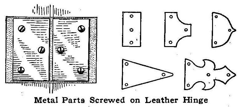
Metal Parts Screwed on Leather Hinge
A method of making a leather hinge work as well as an ordinary
steel butt is to cover the wings with sheet metal. The metal can
be fastened with nails or screws over the parts of the leather
attached to the wood. Tinplate, iron hoops, zinc or thin brass
cut in neat designs will make a leather hinge appear as well as a
metal hinge.
Contributed by Tom Hutchinson, Encanto, Cal.
Removing Plaster from Skin
A hot-water bottle held against a porous plaster will assist in
quickly removing it from the skin.
How to Make a Cheap Bracket Saw
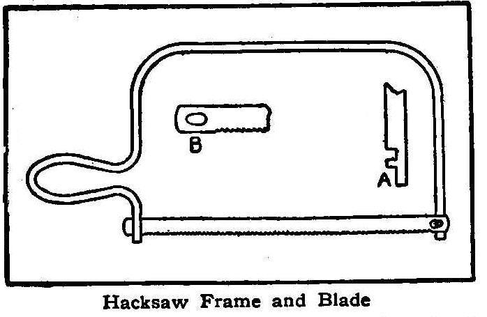
Hacksaw Frame and Blade
For the frame use 3/8-in. round iron, bending it as shown in the
diagram and filing a knob on each end, at opposite sides to each
other, on which to hook the blade.
For the blade an old talking-machine spring or a clock spring
will do nicely. Heat the spring enough to take some of the temper
out of it, in order to drill the holes in the ends, as shown, and
file in the teeth. Make the blade 12 in. long, with 10 teeth to
the inch. A and B show how the blade fits on the frame.
Contributed by Willard J. Hays, Summitville, Ohio.
How to Make a Cannon
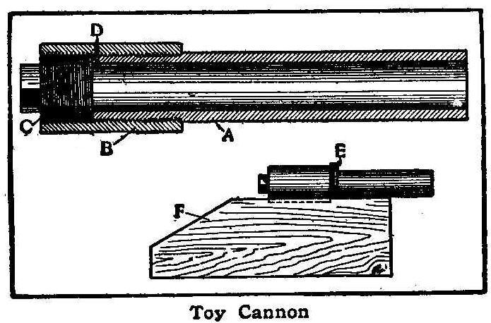
Toy Cannon
A cannon like the one in the cut may be made from a piece of
1-in. hydraulic pipe, A, with a steel sleeve, B, and a long
thread plug, C. Be sure to get hydraulic pipe, or double extra
heavy, as it is sometimes called, as common gas pipe is entirely
too light for this purpose. Don’t have the pipe too long or the
cannon will not make as much noise. Seven or eight inches is
about the right length for a 1-in. bore. Screw the plug and pipe
up tightly and then drill a 1/16-in. fuse hole at D.
If desired the cannon may be mounted on a block of wood, F, by
means of a U-bolt or large staple, E.
Contributed by Carson Birkhead, Moorhead, Miss.
Controller for a Small Motor
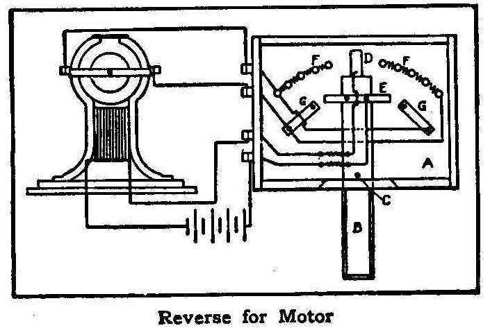
Reverse for Motor
An easy way of making a controlling and reversing device for
small motors is as follows:
Cut a piece of wood (A) about 6 in. by 4-1/2 in., and 1/4 in.
thick, and another piece (B) 6 in. by 1 in., and 1/4 in. thick.
Drive a nail through this near the center for a pivot (C). To the
under side of one end nail a copper brush (D) to extend out about
an inch. On the upper side, at the same end, nail another brush
(E) so that it projects at both sides and is bent down to the
level of the end brush. Then on the board put a semi-circle of
brass-headed tacks as shown at F, leaving a small space at the
middle and placing five tacks on either side, so that the end
brush will come in contact with each one. Connect these tacks on
the under side of the board with coils of German-silver wire,
using about 8 in. of wire to each coil. Fix these by soldering or
bending over the ends of the tacks. Then nail two strips of
copper (G) in such position that the side brush will remain on
the one as long as the end brush remains on the tacks on that
side.
Put sides about 1-1/2 in. high around this apparatus, raising the
board a little from the bottom to allow room for the coil. A lid
may be added if desired. Connect up as shown.
Contributed by Chas. H. Boyd, Philadelphia.
How to Make a Simple Water Rheostat
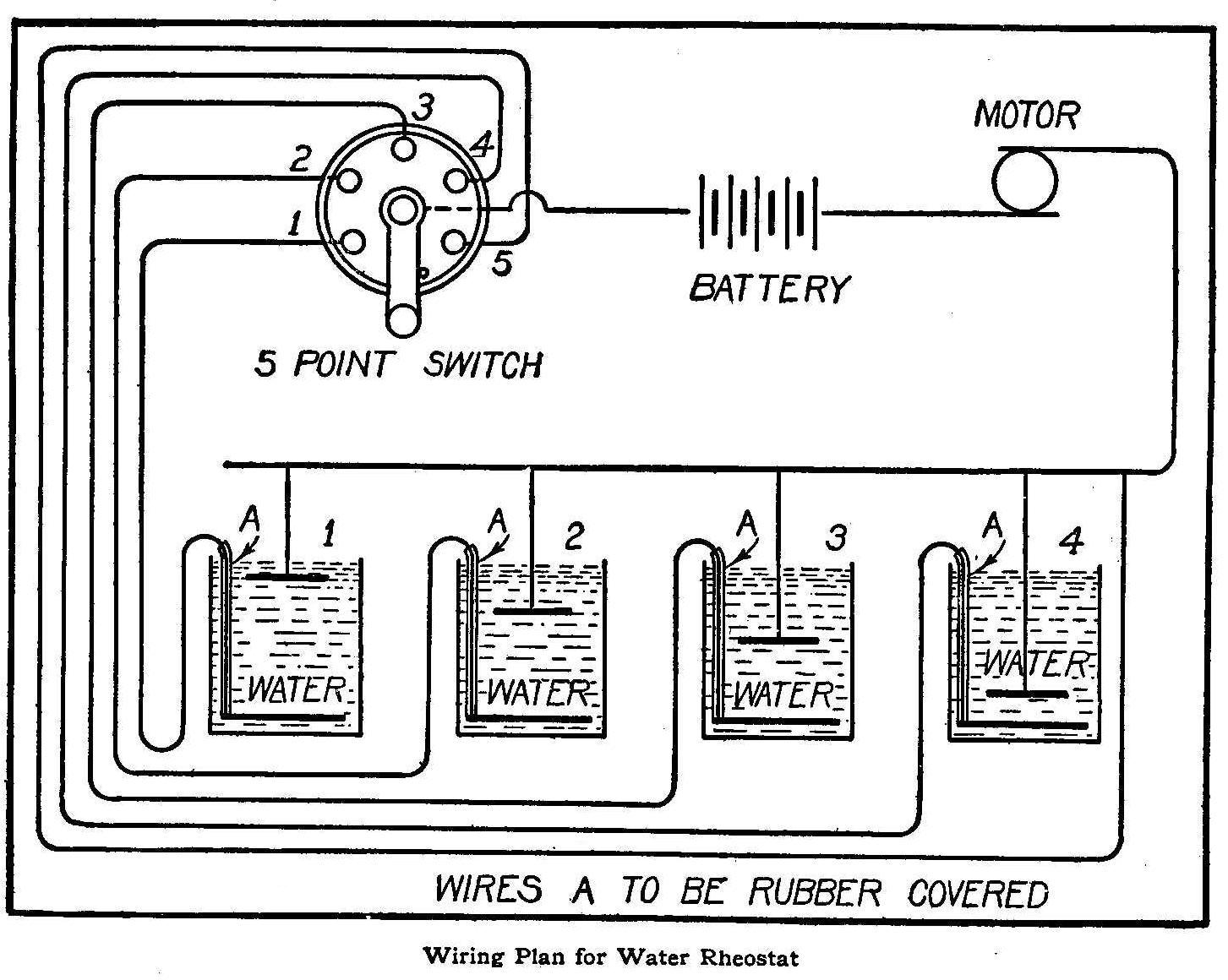
Wiring Plan for Water Rheostat
The materials necessary are: One 5-point wood-base switch, 4
jars, some sheet copper or brass for plates, about 5 ft. of
rubber-covered wire, and some No. 18 gauge wire for the wiring.
The size of the jars depends on the voltage. If you are going to
use a current of low tension, as from batteries, the jars need
not be very large, but if you intend to use the electric light
current of 110 voltage it will be necessary to use large jars or
wooden boxes made watertight, which will hold about 6 or 7 gal.
Each jar to be filled with 20 parts water to 1 part
sulphuric acid.
Jars are set in a row in some convenient place out of the
way.
Next cut out eight copper or brass disks, two for each jar. Their
size also depends on the voltage. The disks that are placed in
the lower part of the jars are connected with a rubber covered
wire extending a little above the top of the jar.
To wire the apparatus, refer to the sketch and you will see that
jar No. 1 is connected to point No. 1 on switch; No. 2, on No. 2,
and so on until all is complete and we have one remaining point
on switch. Above the jars place a wire to suspend the other or
top disks in the solution. This wire is also connected to one
terminal on the motor and to remaining point on switch. The arm
of the switch is connected to one terminal of battery, or source
of current, and the other terminal connected direct to remaining
terminal of motor.
Put arm of switch on point No. 1 and lower one of the top disks
in jar No. 1 and make contact with wire above jars. The current
then will flow through the motor. The speed for each point can be
determined by lowering top disks in jars. The top disk in jar No.
2 is lower down than in No. 1 and so on for No. 3 and No. 4. The
connection between point No. 5 on switch, direct to wire across
jars, gives full current and full speed.
How to Build a Toboggan Sled
By A. Boette
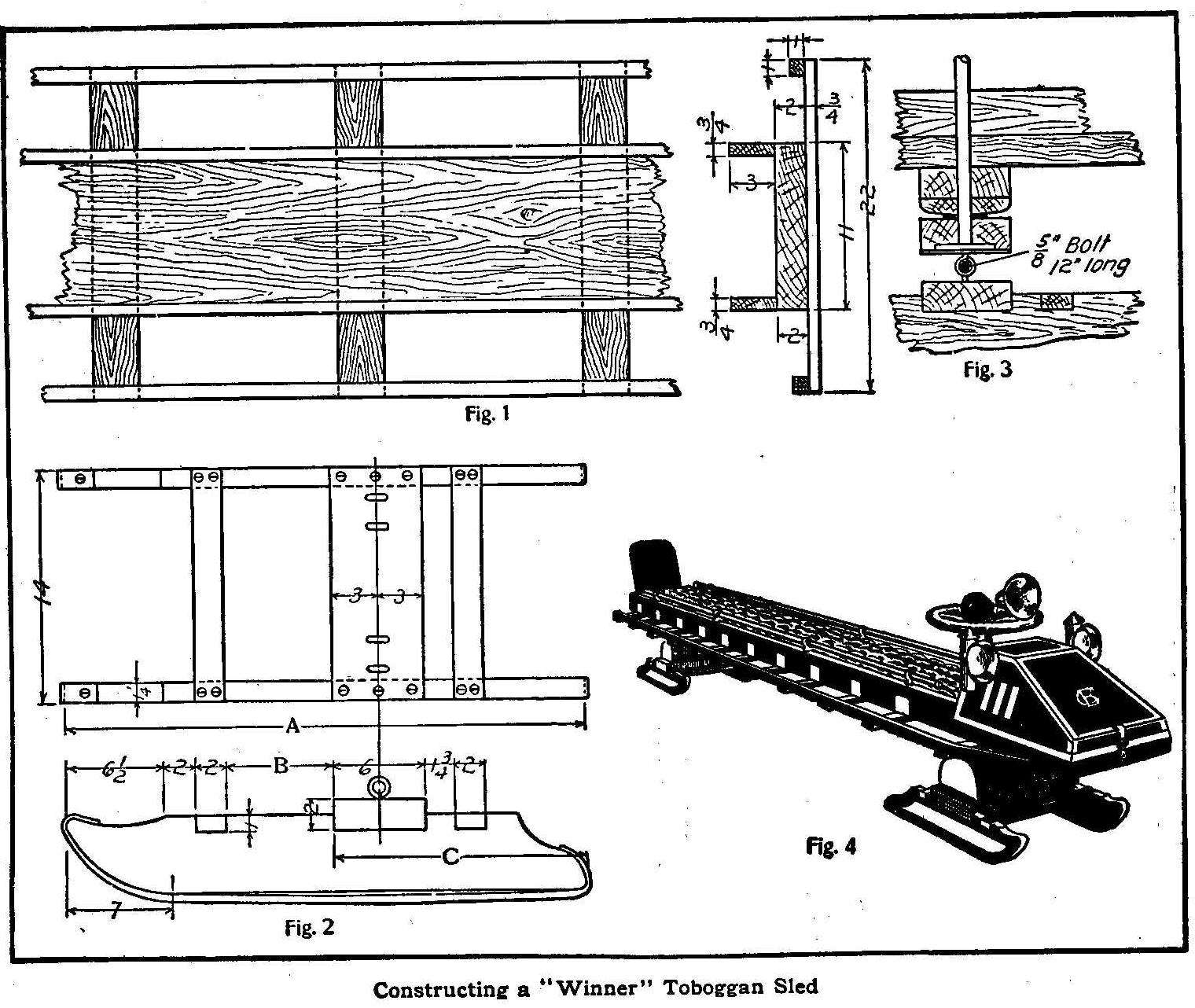
Construction a “Winner” Toboggan Sled
The first object of the builder of a sled should be to have a
“winner” both in speed and appearance. The accompanying
instructions for building a sled are designed to produce these
results.
The sled completed should be 15 ft. 2 in. long by 22 in. wide,
with the cushion about 15 in. above the ground. For the baseboard
select a pine board 15 ft. long, 11 in. wide and 2 in. thick, and
plane it on all edges. Fit up the baseboard with ten oak
foot-rests 22 in. long, 3 in. wide and 3/4 in. thick. Fasten them
on the under side of the baseboard at right angles to its length
and 16 in. apart, beginning at the rear. At the front 24 or 26
in. will be left without cross bars for fitting on the auto
front. On the upper side of the cross bars at their ends on each
side screw a piece of oak 1 in. square by 14 ft. long. On the
upper side of the baseboard at its edge on each side screw an oak
strip 3 in. wide by 3/4 in. thick and the length of the sled from
the back to the auto front. These are to keep the cushion from
falling out. See Fig. 1. For the back of the sled use the upper
part of a child’s high chair, taking out the spindles and
resetting them in the rear end of the baseboard. Cover up the
outside of the spindles with a piece of galvanized iron.
The construction of the runners is shown by Figs. 2 and 3. The
stock required for them is oak, two pieces 30 in. by 5 in. by
1-1/4 in., two pieces 34 in. by 5 in. by 1-1/4 in., two pieces 14
in. by 6 in. by 2 in., and four pieces 14 in. by 2 in. by 1 in.
They should be put together with large screws about 3 in. long.
Use no nails, as they are not substantial enough. In
proportioning them the points A, B and C, Fig. 2, are important.
For the front runners these measurements are: A, 30 in.; B, 4
in.; C, 15-1/2 in., and for the rear runners: A, 34 in.; B, 7 in.;
C, 16-1/2 in. The screw eyes indicated must be placed in a
straight line and the holes for them carefully centered. A
variation of 1/16 in. one way or another would cause a great deal
of trouble. For the steel runners use 3/8 in. cold-rolled steel
flattened at the ends for screw holes. Use no screws on the
running surface, however, as they “snatch” the ice.
The mechanism of the front steering gear is shown at Fig. 3. A
3/4-in. steel rod makes a good steering rod. Flatten the steering
rod at one end and sink it into the wood. Hold it in place by
means of an iron plate drilled to receive the rod and screwed to
block X. An iron washer, Z, is used to reduce friction; bevel
block K to give a rocker motion. Equip block X with screw eyes,
making them clear those in the front runner, and bolt through.
For the rear runner put a block with screw eyes on the baseboard
and run a bolt through.
Construct the auto front (Fig. 4) of 3/4-in. oak boards. The
illustration shows how to shape it. Bevel it toward all sides and
keep the edges sharp, as sharp edges are best suited for the
brass trimmings which are to be added. When the auto front is in
place enamel the sled either a dark maroon or a creamy white.
First sandpaper all the wood, then apply a coat of thin enamel.
Let stand for three days and apply another coat. Three coats of
enamel and one of thin varnish will make a fine-looking sled. For
the brass trimmings use No. 27 B. & S. sheet brass 1 in. wide on
all the front edges and pieces 3 in. square on the cross bars to
rest the feet against. On the door of the auto front put the
monogram of the owner or owners of the sled, cutting it out of
sheet brass.
For the steering-wheel procure an old freight-car “brake” wheel,
brass plated. Fasten a horn, such as used on automobiles, to the
wheel.
Make the cushion of leather and stuff it with hair. The best way
is to get some strong, cheap material, such as burlap, sew up one
end and make in the form of an oblong bag. Stuff this as tightly
as possible with hair. Then get some upholstery buttons, fasten a
cord through the loop, bring the cord through to the underside of
the cushion, and fasten the button by slipping a nail through the
knot. Then put a leather covering over the burlap, sewing it to
the burlap on the under side. Make the cushion for the back in
the same way. On top of the cushion supports run a brass tube to
serve the double purpose of holding the cushion down and
affording something to hold on to.
If desired, bicycle lamps may be fastened to the front end, to
improve the appearance, and it is well to have a light of some
kind at the back to avoid the danger of rear-end collisions.
The door of the auto front should be hinged and provided with a
lock so that skates, parcels, overshoes, lunch, etc. may be
stowed within. A silk pennant with a monogram adds to the
appearance.
If desired, a brake may be added to the sled. This can be a
wrought-iron lever 1-1/2 in. by 1/2 in. by 30 in. long, so
pivoted that moving the handle will cause the end to scrape the
ice. This sled can be made without lamps and horn at a cost of
about $15, or with these for $25, and the pleasure derived from
it well repays the builder. If the expense is greater than one
can afford, a number of boys may share in the ownership.
Burning Inscriptions on Trees
Scrape off the bark just enough to come to the first light under
coating, which is somewhat moist. With a lead pencil make an
outline of the inscription to be burnt on the tree and bring, the
rays of a large magnifying glass not quite to a fine focus on the
same. The tree will be burnt along the pencil marks, and if the
glass is not held in one spot too long, the inscription will be
burnt in as evenly as if it had been written.
Contributed by Stewart H. Leland, Lexington, Ill.
How to Make Small Gearwheels Without a Lathe
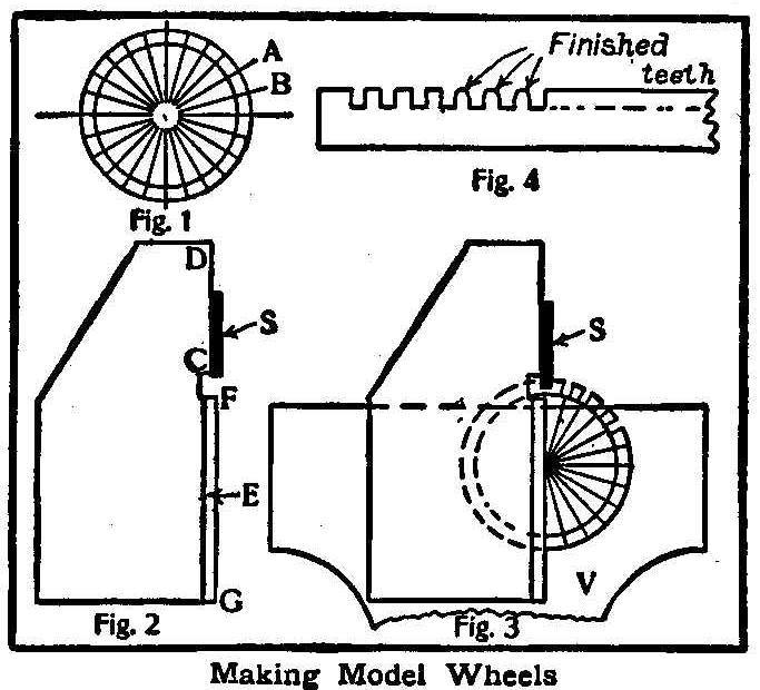
Making Model Wheels
To make small models sundry small gears and racks are required,
either cut for the place or by using the parts from an old clock.
With no other tools than a hacksaw, some files, a compass, and
with the exercise of a little patience and moderate skill, very
good teeth may be cut on blank wheels.
First take the case of a small gearwheel, say 1 in. outside
diameter and 1/16 in. thick, with twenty-four teeth. Draw a
circle on paper, the same diameter as the wheel. Divide the
circumference into the number of parts desired, by drawing
diameters, Fig. 1. The distance AB will be approximately the
pitch. Now describe a smaller circle for the base of the teeth
and halfway between these circles may be taken as the pitch
circle.
Now describe a circle the same size as the largest circle on a
piece of 1/16-in. sheet metal, and having cut it out and filed it
up to this circle, fasten the marked-out paper circle accurately
over it with glue. Saw-cuts can now be made down the diameters to
the smaller circle with the aid of a saw guide, Fig. 2, made from
1/16-in. mild steel or iron. This guide should have a beveled
edge, E, from F to G, to lay along the line on which the saw-cut
is to be made. The straight-edge, CD, should be set back one-half
the thickness of the saw-blades, so that the center of the blade,
when flat against it, will be over the line FG. A small clearance
space, FC, must be made to allow the teeth of the saw to pass.
The guide should then be placed along one of the diameters and
held in position until gripped in the vise, Fig. 3. The first
tooth may now be cut, care being taken to keep the blade of the
saw flat up to the guiding edge. The Model Engineer, London, says
if this is done and the saw-guide well made, the cut will be
central on the line, and if the marking-out is correct the teeth
will be quite uniform all the way round. A small ward file will
be needed to finish off the teeth to their proper shape and
thickness.
In making a worm wheel the cuts must be taken in a sloping
direction, the slope and pitch depending on the slope and pitch
of the worm thread, which, though more difficult, may also be cut
with a hacksaw and file.
A bevel wheel should be cut in the same manner as the spur wheel,
but the cut should be deeper on the side which has the larger
diameter. To cut a rack the pitch should be marked along the
side, and the guide and saw used as before (Fig. 4).
How to Make Four Pictures on One Plate
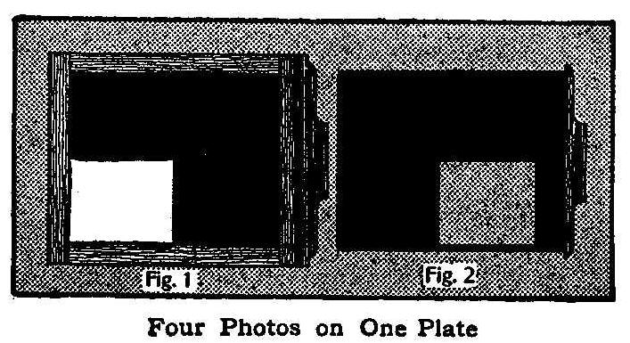
Four Photos on One Plate
Secure two extra slides for the plate holders and cut one corner
out on one of them, as shown in Fig. 1. Make a hole in the other,
as shown in Fig. 2. With a lead pencil draw on the ground glass
one line vertical and one horizontal, each in the center. This
will divide the ground glass into four equal parts.
Focus the camera in the usual manner, but get the picture desired
to fill only one of the parts on the ground glass. Place the
plate-holder in position and draw the regular slide; substitute
one of the slides prepared and expose in the usual way.
If a small picture is to be made in the lower left-hand corner of
the plate, place the prepared slide with the corner cut, as shown
in Fig. 1. The slide may be turned over for the upper left hand
corner and then changed for slide shown in Fig. 2 for the upper
and lower right-hand corners.
Electric Blue-Light Experiment
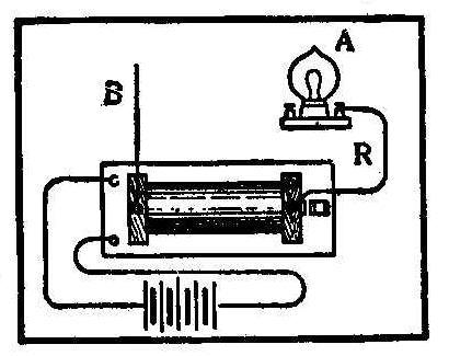
Take a jump-spark coil and connect it up with a battery and start
the vibrator. Then take one outlet wire, R, and connect to one
side of a 2-cp. electric lamp, and the other outlet wire, B, hold
in one hand, and press all fingers of the other hand on globe at
point A. A bright, blue light will come from the wires in the
lamp to the surface of the globe where the fingers touch. No
shock will be perceptible.
Interesting Electrical Experiment
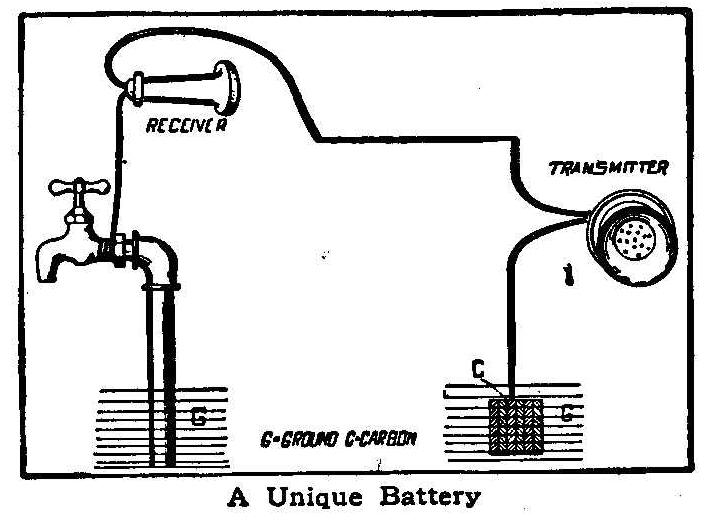
A Unique Battery
The materials necessary for performing this experiment are:
Telephone receiver, transmitter, some wire and some carbons,
either the pencils for arc lamps, or ones taken from old dry
batteries will do.
Run a line from the inside of the house to the inside of some
other building and fasten it to one terminal of the receiver. To
the other terminal fasten another piece of wire and ground it on
the water faucet in the house. If there is no faucet in the
house, ground it with a large piece of zinc.
Fasten the other end to one terminal of the transmitter and from
the other terminal of the same run a wire into the ground. The
ground here should consist either of a large piece of carbon, or
several pieces bound tightly together.
If a person speak into the transmitter, one at the receiver can
hear what is said, even though there are no batteries in the
circuit. It is a well known fact that two telephone receivers
connected up in this way will transmit words between two persons,
for the voice vibrating the diaphragm causes an inductive current
to flow and the other receiver copies these vibrations. But in
this experiment, a transmitter which induces no current is used.
Do the carbon and the zinc and the moist earth form a battery?
Contributed by Wm. J. Slattery, Emsworth, Pa.
A Cheap Fire Alarm
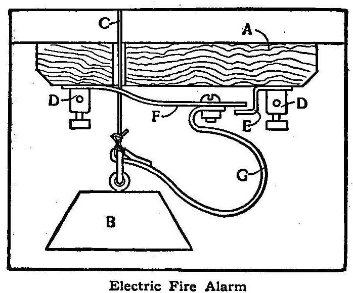
Electric Fire Alarm
An electrical device for the barn that will give an alarm in case
of fire is shown in the accompanying diagram. A is a wooden
block, which is fastened under the loft at a gable end of the
barn; B is an iron weight attached to the string C, and this
string passes up through the barn to the roof, then over a hook
or pulley and across the barn, under the gable, and is fastened
to the opposite end of the barn.
D D are binding posts for electric wires. They have screw ends,
as shown, by which means they are fastened to the wooden block A.
They also hold the brass piece E and the strip of spring brass F
in place against the wooden block. G is a leather strap fastened
to the weight B and the spring F connected to the latter by a
small sink bolt.
At the house an electric bell is placed wherever convenient.
Several battery cells, of course, are also needed. Dry batteries
are most convenient. The battery cells and bell are connected in
the usual manner, and one wire from the bell and one from the
battery are strung to the barn and connected to the binding posts
D D.
If a fire occurs in the hay-mow the blaze will generally shoot
toward the gable soon after it starts, and will then burn the
string C, which allows the weight B to fall and pull the brass
spring against the iron piece E, which closes the circuit and
rings the bell in the house.
If desired, the string may be stretched back and forth under the
roof several times or drawn through any place that is in danger
of fire.
Contributed by Geo. B. Wrenn, Ashland, Ohio.
How to Make a Small Electric Furnace
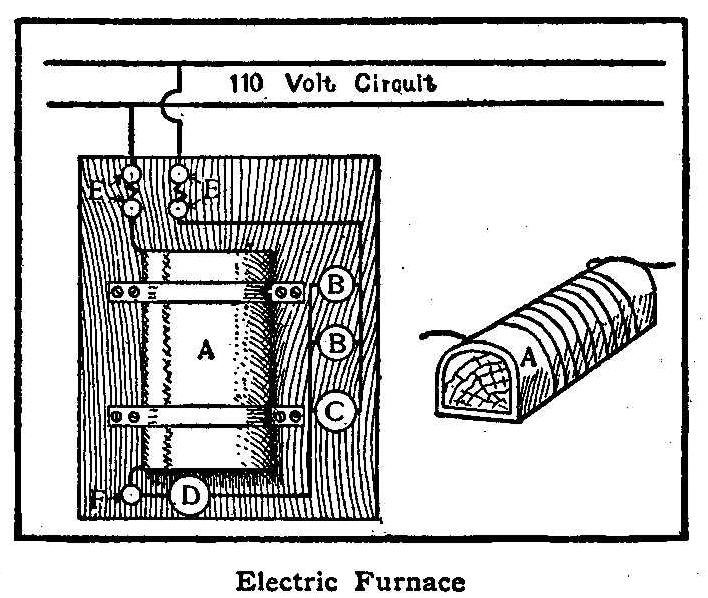
Electric Furnace
Take a block of wood and shape into a core. One like a loaf of
bread, and about that size, serves admirably. Wrap a layer of
asbestos
around it and cover this with a thin layer of
plaster-of-paris. When the plaster is nearly dry wind a coil of
No. 36 wire around it, taking care that the wire does not touch
itself anywhere. Put another course of plaster-of-paris on this,
and again wind the wire around it. Continue the process of
alternate layers of plaster and wire until 500 ft. or more of the
latter has been used, leaving about 10 in. at each end for
terminals. Then set the whole core away to dry.
For a base use a pine board 10 in. by 12 in. by 1 in. Bore four
holes at one end for binding-posts, as indicated by E E. Connect
the holes in pairs by ordinary house fuse wire. At one side
secure two receptacles, B B, and one single post switch, C. Place
another switch at I and another binding-post at F. The oven is
now ready to be connected.
Withdraw the wooden core from the coils of wire and secure the
latter by bands of tin to the board. Connect the ends of the wire
to binding-posts E and F, as shown. From the other set of
binding-posts, E, run a No. 12 or No. 14 wire, connecting lamp
receptacles, B B, and switch, C, in parallel. Connect these three
to switch, D, in series with binding-post, F, the terminal of the
coil. Place 16-cp. lights in the receptacles and connect the
fuses with a 110-volt lighting circuit. The apparatus is now
ready for operation. Turn on switch, D, and the lamps, while C is
open. The coil will commence to become warm, soon drying out the
plaster-of-paris. To obtain more heat open one lamp, and to
obtain still more open the other and close switch C.
Contributed by Eugene Tuttles, Jr., Newark, Ohio.
How to Make an Ammeter
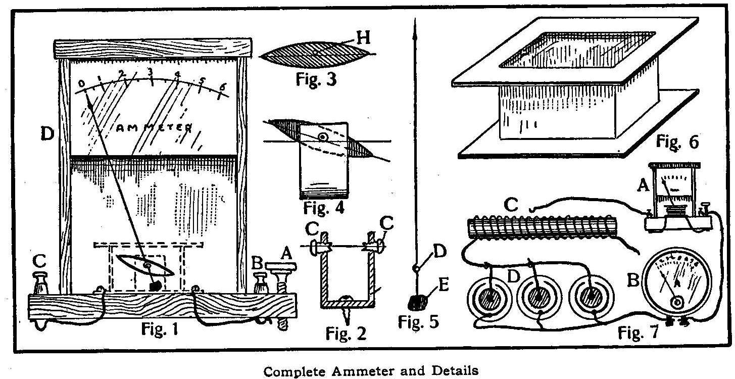
Complete Ammeter and Details
Every amateur mechanic who performs electrical experiments will
find use for an ammeter, and for the benefit of those who wish to
construct such an instrument the following description is given:
The operative principle of this instrument is the same as that of
a galvanometer, except that its working position is not confined
to the magnetic meridian. This is accomplished by making the
needle revolve in a vertical instead of a horizontal plane. The
only adjustment necessary is that of leveling, which is
accomplished by turning the thumbscrew shown at A, Fig. 1, until
the hand points to zero on the scale.
First make a support, Fig. 2, by bending a piece of sheet brass
to the shape indicated and tapping for the screws CC. These
should have hollow ends, as shown, for the purpose of receiving
the pivoted axle which supports the hand. The core, Fig. 3, is
made of iron. It is 1 in. long, 1/4 in. wide and 1/8 in. thick.
At a point a little above the center, drill a hole as shown at H,
and through this hole drive a piece of knitting-needle about 1/2
in. long, or long enough to reach between the two screws shown in
Fig. 2. The ends of this small axle should be ground pointed and
should turn easily in the cavities, as the sensitiveness of the
instrument depends on the ease with which this axle turns.
After assembling the core as shown in Fig. 4, it should be filed
a little at one end until it assumes the position indicated. The
pointer or hand, Fig. 5, is made of wire, aluminum being
preferable for this purpose, although copper or steel will do.
Make the wire 4-1/2 in. long and make a loop, D, 1/2 in. from the
lower end. Solder to the short end a piece of brass, E, of such
weight that it will exactly balance the weight of the hand. This
is slipped on the pivot, and the whole thing is again placed in
position in the support. If the pointer is correctly balanced it
should take the position shown in Fig. 1, but if it is not
exactly right a little filing will bring it near enough so that
it may be corrected by the adjusting-screw.
Next make a brass frame as shown in Fig. 6. This may be made of
wood, although brass is better, as the eddy currents set up in a
conductor surrounding a magnet tend to stop oscillation of the
magnet. (The core is magnetized when a current flows through the
instrument.) The brass frame is wound with magnet wire, the size
depending on the number of amperes to be measured. Mine is wound
with two layers of No. 14 wire, 10 turns to each layer, and is
about right for ordinary experimental purposes. The ends of the
wire are fastened to the binding posts B and C, Fig. 1.
A wooden box, D, is then made and provided with a glass front. A
piece of paper is pasted on a piece of wood, which is then
fastened in the box in such a position that the hand or pointer
will lie close to the paper scale. The box is 5-1/2 in. high, 4
in. wide and 1-3/4 in. deep, inside measurements. After
everything is assembled put a drop of solder on the loop at D,
Fig. 5, to prevent it turning on the axle.
To calibrate the instrument connect as shown in Fig. 7, where A
is the homemade ammeter; B, a standard ammeter; C, a variable
resistance, and D, a battery, consisting of three or more cells
connected in multiple. Throw in enough resistance to make the
standard instrument read 1 ohm [sic: ampere] and then put a mark
on the paper scale of the instrument to be calibrated. Continue
in this way with 2 amperes, 3 amperes, 4 amperes, etc., until the
scale is full. To make a voltmeter out of this instrument, wind
with plenty of No. 36 magnet wire instead of No. 14, or if it is
desired to make an instrument for measuring both volts and
amperes, use both windings and connect to two pairs of binding
posts.
Contributed by J.E. Dussault, Montreal.
How to Make a Three-Way Cock for Small Model-Work
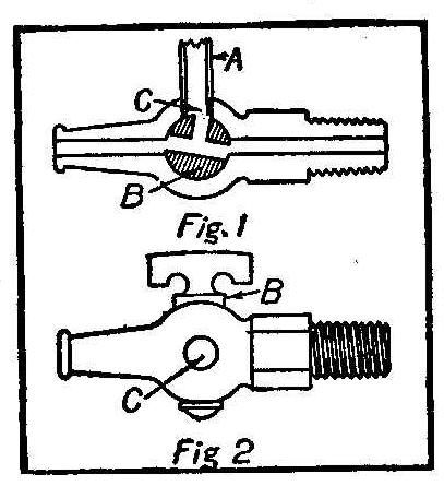
In making models of machines it is often necessary to contrive
some method for a 3 or 4-way valve or cock. To make one, secure
a pet cock and drill and tap hole through, as shown in the cut.
If for 3-way, drill in only to the opening already through, but
if for a 4-way, drill through the entire case and valve. Be sure
to have valve B turned so as to drill at right angles to the
opening through it. After drilling, remove the valve, take off
the burr with a piece of emery paper and replace ready for work.
Easy Experiments with Electric-Light Circuit
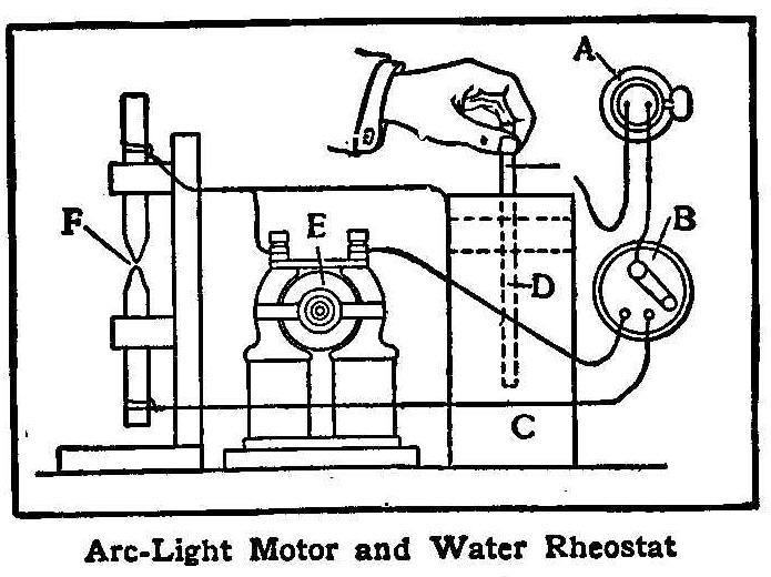
Arc-Light Motor and Water Rheostat
An electric-light circuit will be found much less expensive than
batteries for performing electrical experiments. The sketch shows
how a small arc light and motor may be connected to the light
socket, A. The light is removed and a plug with wire connections
is put in its place. One wire runs to the switch, B, and the
other connects with the water rheostat, which is used for
reducing the current.
A tin can, C is filled nearly to the top with salt water, and a
metal rod, D, is passed through a piece of wood fastened at the
top of the can. When the metal rod is lowered the current
increases, and as it is withdrawn the current grows weaker. In
this way the desired amount of current can be obtained. By
connecting the motor, E, and the arc light, F, as shown, either
one may be operated by turning switch B to the corresponding
point. The arc light is easily made by fastening two electric
light carbons in a wooden frame like that shown. To start the
light, turn the current on strong and bring the points of the
carbons together; then separate slightly by twisting the upper
carbon and at the same time drawing it through the hole.
How to Make an Interrupter
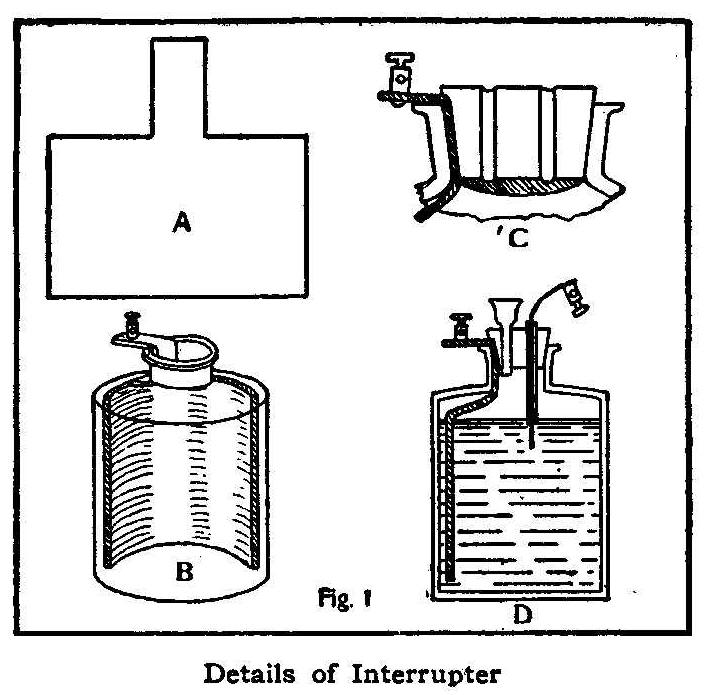
Details of Interrupter
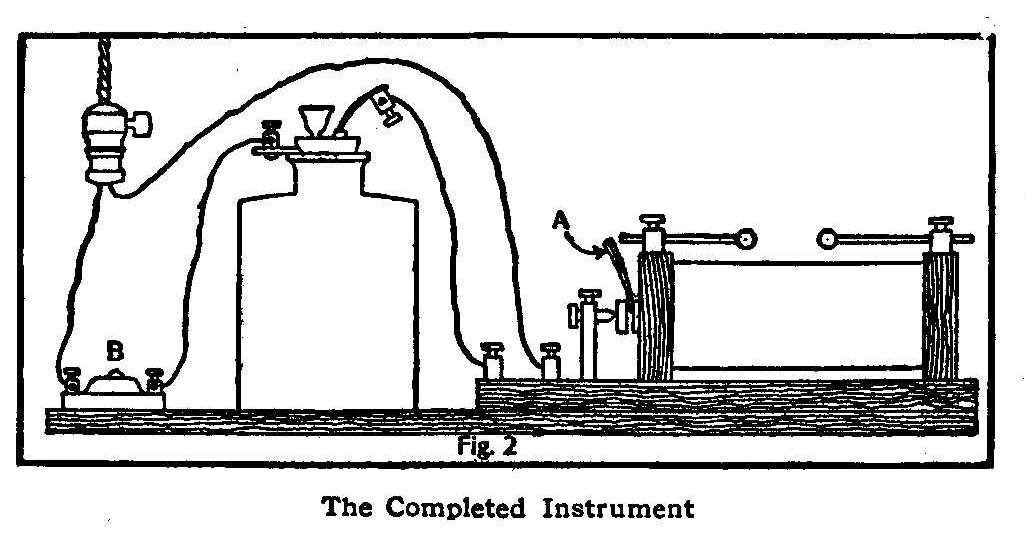
The Completed Instrument
The Wenult interrupter is an instrument much used on large coils
and is far more efficient than the usual form of vibrators. It
can also be used with success on small coils as well as large.
Although it is a costly instrument to purchase, it can be made
with practically no expense and the construction is very simple.
First procure a wide-mouthed bottle about 4 in. high, provided
with a rubber stopper. This stopper should be pierced, making two
holes about 1/4 in. in diameter.
From a sheet of lead 1/16 in.
in thickness cut a piece shaped
like A, Fig. 1. Common tea lead
folded several times will serve
the purpose. When in the bottle this
lead should be of such a
size that it will only reach half way around, as shown in B. To
insert the lead plate,
roll it up so it will pass through the
neck of the bottle, then smooth it out with a small stick until
it fits against the side, leaving the small strip at the top
projecting through the neck of the bottle. Bend this strip to one
side and fit in the stopper, as shown in C. A small binding-post
is fastened at the end of the strip.
Having fixed the lead
plate in position, next get a piece of
glass tube having a bore of about 1/32 of an inch in diameter. A
piece of an old thermometer tube will serve this purpose. Insert
this tube in the hole in the stopper farthest from the
lead
plate. Get a piece of wire that will fit the tube and about 6 in.
long, and fasten a small binding-post on one end and stick the
other into the tube. This wire should fit the hole in the tube so
it can be easily moved. In the hole nearest the
lead plate insert a small glass funnel.
The interrupter as it is when complete is shown at D, Fig. 1.
Having finished the interrupter, connect it with the
electric-light circuit as shown in Fig. 2. Fill the bottle with
water to about the line as shown in D, Fig. 1. Adjust the wire in
the small glass tube so that it projects about 1/8 in. Add
sulphuric acid until the water level rises about 1/16 in. Turn on
the current and press the button, B. If all adjustments are
correct, there will be a loud crackling noise from the
interrupter, a violet flame will appear at the end of the wire
and a hot spark will pass between the secondary terminals. If the
interrupter does not work at first, add more sulphuric acid
through the funnel and press the wire down a little more into the
liquid. A piece of wood, A, Fig. 2, should be inserted in
vibrator to prevent it from working.
Contributed by Harold L. Jones, Carthage, N. Y.
A Miniature “Pepper’s Ghost” Illusion
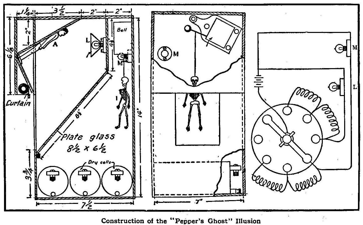
Construction of the “Pepper’s Ghost” Illusion
Probably many readers have seen a “Pepper’s Ghost” illusion at
some amusement place. As there shown, the audience is generally
seated in a dark room at the end of which there is a stage with
black hangings. One of the audience is invited onto the stage,
where he is placed in an upright open coffin. A white shroud is
thrown over his body, and his clothes and flesh gradually fade
away till nothing but his skeleton remains, which immediately
begins to dance a horrible rattling jig. The skeleton then fades
away and the man is restored again.
A simple explanation is given in the Model Engineer. Between the
audience and the coffin is a sheet of transparent glass, inclined
at an angle so as to reflect objects located behind the scenes,
but so clear as to be invisible to the audience and the man in
the coffin. At the beginning the stage is lighted only from
behind the glass. Hence the coffin and its occupant are seen
through the glass very plainly. The lights in front of the glass
(behind the scenes) are now raised very gradually as those behind
the glass are turned down, until it is dark there. The perfectly
black surface behind the glass now acts like the silver backing
for a mirror, and the object upon which the light is now
turned—in this case the skeleton—is reflected in the glass,
appearing to the audience as if really occupying the stage.
The model, which requires no special skill except that of
carpentry, is constructed as shown in the drawings.
The box containing the stage should be 14 in. by 7 in. by 7-1/2
in., inside dimensions. The box need not be made of particularly
good wood, as the entire interior, with the exception of the
glass, figures and lights, should be colored a dull black. This
can well be done by painting with a solution of lampblack in
turpentine. If everything is not black, especially the joints and
background near A, the illusion will be spoiled.
The glass should be the clearest possible, and must be thoroughly
cleansed. Its edges should nowhere be visible, and it should be
free from scratches and imperfections. The figure A should be a
doll about 4 in. high, dressed in brilliant, light-colored
garments. The skeleton is made of papier maché, and can be bought
at Japanese stores. It should preferably be one with arms
suspended by small spiral springs, giving a limp, loose-jointed
effect. The method of causing the skeleton to dance is shown in
the front view. The figure is hung from the neck by a blackened
stiff wire attached to the hammer wire of an electric bell, from
which the gong has been removed. When the bell works he will kick
against the rear wall, and wave his arms up and down, thus giving
as realistic a dance as anyone, could expect from a skeleton.
The lights, L and M, should be miniature electric lamps, which
can be run by three dry cells. They need to give a fairly strong
light, especially L, which should have a conical tin reflector to
increase its brilliancy and prevent its being reflected in the
glass.
Since the stage should be some distance from the audience, to aid
the illusion, the angle of the glass and the inclination of the
doll, A, has been so designed that if the stage is placed on a
mantle or other high shelf, the image of A will appear upright to
an observer sitting in a chair some distance away, within the
limits of an ordinary room. If it is desired to place the box
lower down, other angles for the image and glass may be found
necessary, but the proper tilt can be found readily by
experiment.
The electric connections are so simple that they are not shown in
the drawings. All that is necessary is a two-point switch, by
which either L or M can be placed in circuit with the battery,
and a press button in circuit with the bell and its cell. If a
gradual transformation is desired, a double-pointed rheostat
could be used, so that as one light dims the other increases in
brilliancy, by the insertion and removal of resistance coils.
With a clear glass and a dark room this model has proved to be
fully as bewildering as its prototype.
Experiment with Colored Electric Lamps
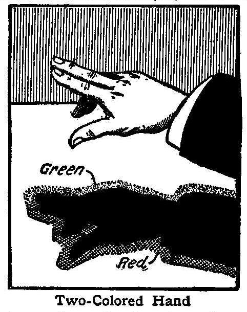
Two-Colored Hand
To many the following experiment may be much more easily
performed than explained: Place the hand or other object in the
light coming from two incandescent lamps, one red and one white,
placed about a foot apart, and allow the shadow to fall on a
white screen such as a table-cloth. Portions of the shadow will
then appear to be a bright green. A similar experiment consists
in first turning on the red light for about a minute and then
turning it off at the same time that the white one is turned on.
The entire screen will then appear to be a vivid green for about
one second, after which it assumes its normal color.
To Explode Powder with Electricity
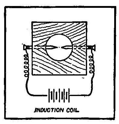
A 1-in. hole was bored in the center of a 2-in. square block. Two
finishing nails were driven in, as shown in the sketch. These
were connected to terminals of an induction coil. After
everything was ready the powder was poured in the hole and a
board weighted with rocks placed over the block. When the button
is pressed or the circuit closed in some other way the discharge
occurs. The distance between the nail points—which must be
bright and clean—should be just enough to give a good, fat
spark.
Contributed by Geo. W. Fry, San Jose, Cal.
Simple Wireless System
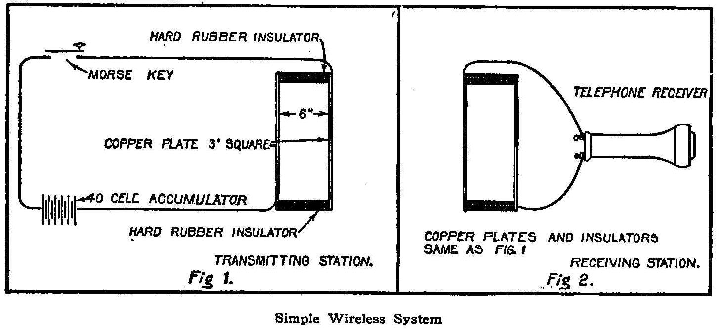
Simple Wireless System
The illustrations will make plain a simple and inexpensive
apparatus for wireless telegraphy by which I have had no
difficulty in sending messages across 1-1/2 miles of water
surface. It is so simple that the cuts scarcely need explanation.
In Fig. 1 is seen the sending apparatus, consisting of a 40-cell
battery connected with two copper plates 36 by 36 by 1/8 in. The
plates are separated 6 in. by a piece of hard rubber at each end.
In Fig. 2 are seen duplicates of these insulated plates,
connected with an ordinary telephone receiver. With this receiver
I can hear distinctly the electric signals made by closing and
opening the Morse key in Fig. 1, and I believe that in a short
time I shall be able to perfect this system so as to send
wireless messages over long distances.
Contributed by Dudley H. Cohen, New York.
Stop Crawling Water Colors
To prevent water colors from crawling, add a few drops of ammonia
or lime water, or a solution of sal soda.
Small Electrical Hydrogen Generator
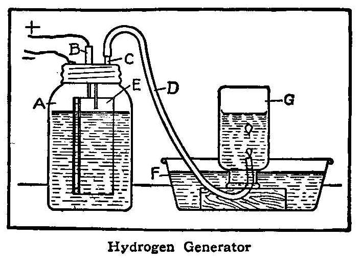
Hydrogen Generator
A small hydrogen
generator may be made from a fruit jar, A (see
sketch), with two tubes, B and C, soldered in the top. The plates
E can be made of tin or galvanized iron, and should be separated
about 1/8 in. by small pieces of wood. One of these plates is
connected to metal top, and the wire from the other passes
through the tube B, which is filled with melted rosin or wax, to
make it airtight. This wire connects to one side of a battery of
two cells, the other wire being soldered to the metal top of the
jar, as shown. The jar is partly filled with a very dilute
solution of sulphuric acid, about 1 part of acid to 20 of water.
When the current of electricity passes between the plates E,
hydrogen gas is generated,
which rises and passes through the
rubber hose D, into the receiver G. This is a wide-mouth bottle,
which is filled with water and inverted over a pan of water, F.
The gas bubbling up displaces the water and fills the bottle. If
the receiver is removed when half full of gas, the remaining
space will be filled with air, which will mix with the gas and
form an explosive mixture. If a lighted match is then held near
the mouth of the bottle a sharp report will be heard.
If the bottle is fitted with a cork containing two wires nearly
touching, and the apparatus connected with an induction coil, in
such a manner that a spark will be produced inside the bottle,
the explosion will blowout the cork or possibly break the bottle.
Caution should be used to avoid being struck by pieces of flying
glass if this experiment is tried, and under no condition should
a lighted match or spark be brought near the end of the rubber
hose D, as the presence of a little air in the generator will
make an explosive mixture which would probably break the jar.
Gasoline Burner for Model Work
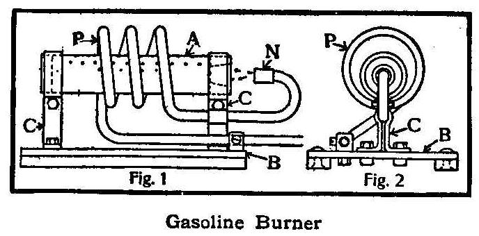
Gasoline Burner
When making a small model traction engine or a locomotive the
question arises, “What shall the fuel be?” If you have decided to
use gasoline, then a suitable burner is necessary. A piece of
brass tubing about 3 in. in diameter and 6 in. long with caps
screwed on both ends and fitted with a filling plug and a bicycle
valve makes a good gasoline supply tank, says the Model Engineer,
London. The bicycle valve is used to give the tank an air
pressure which forces the gasoline to the burner.
The burner is made from a piece of brass tube, A, as is shown in
the illustration, 1/2 in. in diameter and 2-1/2 in. long, which
is plugged up at both ends, one end being drilled and reamed out
to 5/16 in. Three rows of holes 1/16 in. in diameter are drilled
in the brass tube. One row is drilled to come directly on top,
and the other two at about 45 degrees from the vertical. It is
then fitted to a sheet steel base, B, by means of the clips, C C,
Fig. 1. A piece of 1/8-in. copper pipe, P, is then coiled around
the brass tube, A, which forms the vaporizing coil. This coil
should have a diameter of only 1 in. One end of the copper tube
is bent around so it will point directly into the reamed-out hole
in the end of the brass tube, A. A nipple, N, is made by
drilling a 1/8-in. hole halfway through a piece of brass and
tapping to screw on the end of the 1/8-in. copper pipe. A
1/64-in. hole is then drilled through the remaining part of the
nipple. The other end of the copper tube is connected to the
supply tank. The distance between the nipple, N, and the ends of
the tube, A, should be only 5/16 of an inch. Fig. 2 shows the end
view.
A Homemade Telephone Receiver
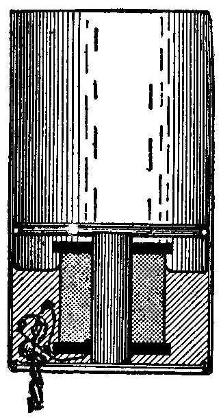
A telephone receiver that will do good work may be built very
cheaply as follows: For the case use an ordinary 1/2-lb.
baking-powder box with a piece of heavy wire soldered on the
inside, 1-5/16 in. from the bottom. For the magnet use a piece of
round hardened steel about 3/8 in. in diameter and 1-1/4 in.
long. If desired, a piece of an old round file may be used for
the magnet core, which should be magnetized previous to
assembling, either by passing a current of electricity around it,
or by direct contact with another magnet. The steel core should
be wound with about 250 ft. of No. 36 insulated wire, the ends of
which should be soldered to a piece of lamp cord, passed through
a hole in the bottom of the can and knotted inside to prevent
pulling out.
A disk of thin sheet-iron, such as is used by photographers for
tintypes (Ferrotype), should be cut to the diameter of the can,
taking care not to bend the iron. The magnet should then be
placed in the bottom of the can in an upright position and enough
of a melted mixture of beeswax and resin poured in to hold it in
position.
While the wax is still in a plastic condition the magnet should
be located centrally and adjusted so that the end will be 1/16
in. or less below the level of the top of the copper ring. After
the wax has hardened the disk is slipped in and fastened tightly
by a ring of solder when the instrument is ready for use.
How to Bind Magazines
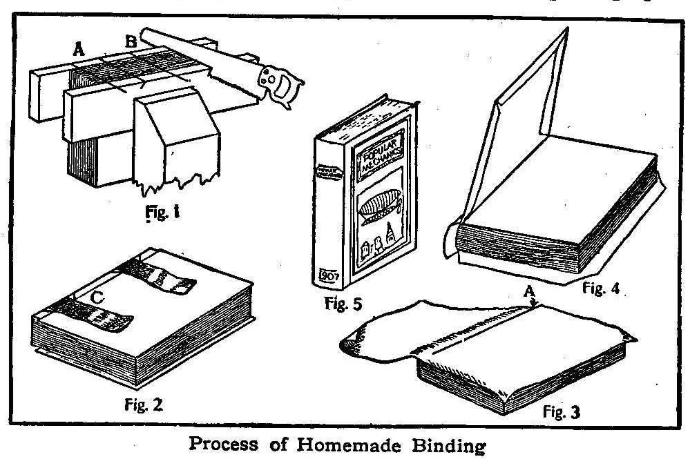
Process of Homemade Binding
An easy way to bind Popular Mechanics in volumes of six months
each is to arrange the magazines in order and tie them securely
both ways with a strong cord. It is well to put two or three
sheets of tough white paper, cut to the size of the pages, at the
front and back for fly leaves.
Clamp the whole in a vise or clamp with two strips of wood even
with the back edges of the magazines. With a sharp saw cut a slit
in the magazines and wood strips about 1/2 in. deep and slanting
as shown at A and B, Fig. 1. Take two strips of stout cloth,
about 8 or 10 in. long and as wide as the distance between the
bottoms of the sawed slits. Lay these over the back edge of the
pack and tie securely through the slits with a string
thread—wrapping and tying several times (C, Fig. 2).
If you have access to a printer’s paper knife, trim both ends and
the front edge; this makes a much nicer book, but if the paper
knife cannot be used, clamp the whole between two boards and saw
off the edges, boards and all, smoothly, with a fine saw.
Cut four pieces of cardboard, 1/4 in. longer and 1/4 in. narrower
than the magazines after they have been trimmed. Lay one piece of
the board on the book and under the cloth strips. Use ordinary
flour paste and paste the strips to the cardboard and then rub
paste all over the top of the strips and the board. Rub paste
over one side of another piece of board and put it on top of the
first board and strips, pressing down firmly so that the strips
are held securely between the two boards. Turn the book over and
do the same with the other two boards.
After the paste has dried a few minutes take a piece of strong
cloth, duck or linen, fold and cut it 1 in. larger all around
than the book, leaving the folded edge uncut. Rub paste over one
of the board backs and lay one end of the cloth on it, smoothing
and creasing as shown at A, Fig. 3. Turn the book over and paste
the other side. The back edges should have a good coat of paste
and a strip of paper the width of the thickness of the pack
pasted on before pasting the cloth to the second board back.
Cut off the corners and fold over the edges of the cloth, pasting
them down (Fig. 4). Rub paste on one side of a fly leaf and press
the back down on it. Turn the book over and paste a fly leaf to
the other back after the edges of the cloth have been folded
down. The backs must not be opened until the fly leaves are
thoroughly dry. Trim and tuck in the ends of the strip at the
back edge. When fixed this way your magazines make one of the
most valuable volumes you can possibly add to your library of
mechanical books.
Contributed by Joseph N. Parker, Bedford City, Va.
A Homemade Acetylene-Gas Generator
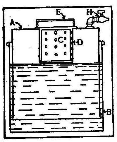
A simple acetylene-gas
generator used by myself for several years
when out on camping trips was made of a galvanized iron tank,
without a head, 18 in. in diameter and 30 in. deep, B, as shown
in the sketch. Another tank, A, is made the same depth as B, but
its diameter is a little smaller, so that inverted it will just
slip easily into the tank B. In the bottom, or rather the top
now, of tank A is cut a hole, and a little can, D, is fitted in
it and soldered. On top and over can D is soldered a large tin
can screw. A rubber washer is fitted on this so that when the
screw top, E, is turned on it, the joint will be gas tight.
Another can, C, which will just slip inside the little can, is
perforated with a number of holes. This can C is filled about
half full of broken pieces of carbide and then placed in the
little can D. A gas cock, H, is soldered onto tank A, as shown,
from which the gas may be taken through a rubber tube. Fill tank
B with water and set tank A into it. This will cause some air to
be enclosed, which can be released by leaving the cock open until
tank A settles down to the point where the water will begin to
run in the perforations of the little tank. The water then comes
in contact with the carbide and forms gas, which expands and
stops the lowering of tank A. Then the cock must be closed and
tubing attached. It is dangerous to attempt to strike a match to
light a jet or the end of the cock while air is escaping and
just as the first gas is being made. Wait until the tank is well
raised up before doing this.
Contributed by James E. Noble, Toronto, Ont.
Homemade Annunciator
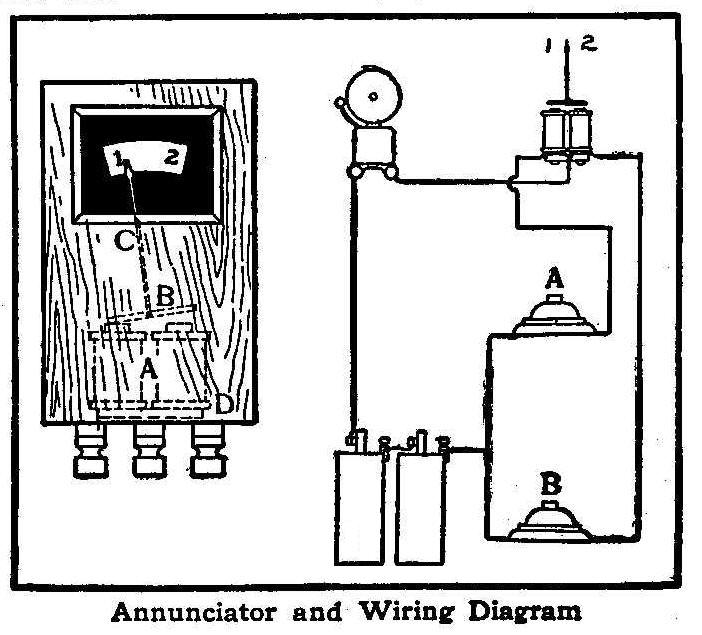
Annuciator and Wiring Diagram
When one electric bell is operated from two push-buttons it is
impossible to tell which of the two push-buttons is being
operated unless an annunciator or similar device is used. A very
simple annunciator for indicating two numbers can be made from a
small box, Fig. 1, with an electric-bell magnet, A, fastened in
the bottom. The armature, B, is pivoted in the center by means of
a small piece of wire and has an indicator or hand, C, which
moves to either right or left, depending on which half of the
magnet is magnetized. If the back armature, D, of the magnet is
removed the moving armature will work better, as this will
prevent the magnetism from acting on both ends of the armature.
The wiring diagram, Fig. 2, shows how the connections are to be
made. If the pushbutton A is closed; the bell will ring and the
pointer will point at 1, while the closing of the push-button B
will ring the bell, and move the pointer to 2.
Contributed by H. S. Bott, Beverly, N. J.
How to Make a Box Kite
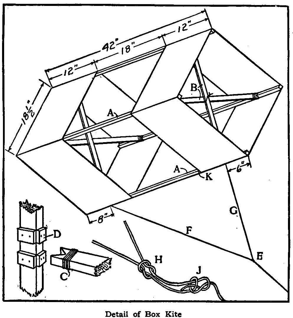
Detail of Box Kite
As some of the readers of Amateur Mechanics may desire to build a
box kite, a simple method of constructing one of the modern type
is given in detail as follows: The sticks should be made of
straight grained wood, which may be either spruce, basswood or
white pine. The longitudinal corner spines, A A, should be 3/8
in. square by 42 in. long, and the four diagonal struts, B,
should be 1/4 in. by 1/2 in., and about 26 in. long. Two cloth
bands should be made to the exact dimensions given in the sketch
and fastened to the four longitudinal sticks with 1 oz. tacks. It
is well to mark the positions of the sticks on the cloth bands,
either with a soft lead-pencil or crayon, in order to have the
four sides of each band exactly equal. The ends of the bands
should be lapped over at least 1/2 in. and sewed double to give
extra strength, and the edges should be carefully hemmed, making
the width, when finished, exactly 12 in. Probably the best cloth
for this purpose is nainsook, although lonsdale cambric or
lightweight percaline will answer nearly as well.
The diagonal struts, B, should be cut a little too long, so that
they will be slightly bowed when put in position, thus holding
the cloth out taut and flat. They should be tied together at the
points of intersection and the ends should be wound with coarse
harness maker’s thread, as shown at C, to prevent splitting. The
small guards, D, are nailed or glued to the longitudinal sticks
to prevent the struts slipping out of position. Of course the
ends of the struts could be fastened to the longitudinal strips
if desired, but if made as described the kite may be readily
taken apart and rolled up for convenience in carrying.
The bridle knots, E, are shown in detail at H and J. H is a
square knot, which may be easily loosened and shifted to a
different position on the bridle, thus adjusting the lengths of F
and G. A bowline knot should be tied at J, as shown, to prevent
slipping. If the kite is used in a light wind, loosen the square
knot and shift nearer to G, thus shortening G and lengthening F,
and if a strong wind is blowing, shift toward F, thereby
lengthening G and making F shorter. In a very strong wind do not
use the bridle, but fasten a string securely to the stick at K.
Contributed by Edw. E. Harbert, Chicago.
Lubricating a Camera Shutter
An experienced photographer uses blacklead [graphite] for grooves
about a camera or holder. A small quantity is rubbed well into
the grooves and on the edges of shutters, that refuse to slide
easily, with gratifying results. Care must be taken to allow no
dust to settle in the holders, however.
Simple Open-Circuit Telegraph Line
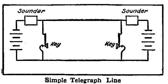
Simple Telegraph Line
By using the circuit shown in the sketch for short-distance
telegraph lines, the extra switches and wiring found in many
circuits are done away with. Closing either key will operate both
sounders, and, as the resistance of the sounders is very high,
the batteries do not run down for a long time.
Contributed by A. D. Stoddard, Clay Center, Kan.
How to Make a Thermo Battery
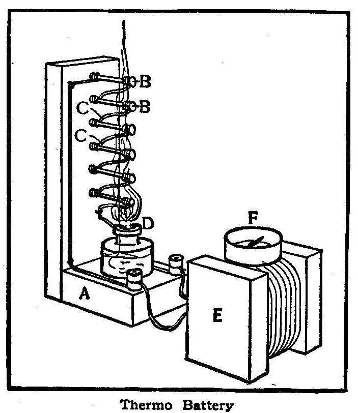
Thermo Battery
A thermo battery, for producing electricity direct from heat, can
be made of a wooden frame, A, with a number of nails, B, driven
in the vertical piece and connected in series with heavy copper
wires, C. The connections should all be soldered to give good
results, as the voltage is very low and the resistance of an
unsoldered joint would stop the current.
The heat may be supplied by an alcohol lamp or other device, and
the current may then be detected by means, of a simple
galvanometer consisting of a square spool of No. 14 or No. 16
single-covered wire, E, with a pocket compass, F, placed on top.
Turn the spool in a north and south direction, or parallel with
the compass needle. Then, when the nail heads are heated and the
circuit completed, the needle will swing around it at right
angles to the coils of wire. Applying ice or cold water to the
nail heads will reverse the current.
Contributed by A. C. A., Chicago.
How to Discharge a Toy Cannon by Electricity
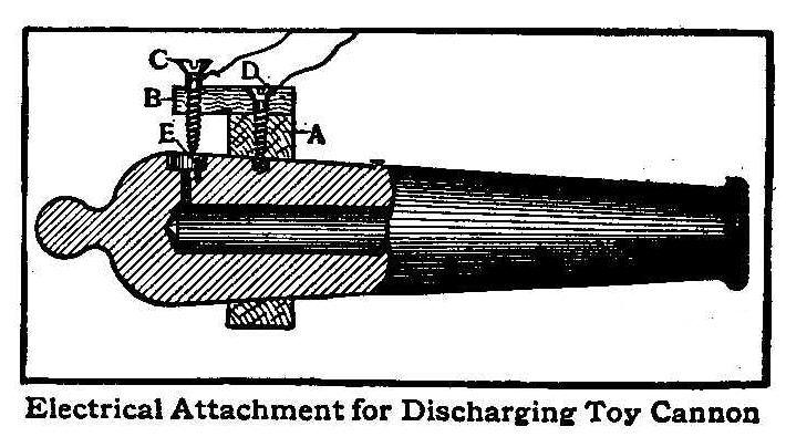
Electrical Attachment for Discharging Toy Cannon
A device for discharging a toy cannon by electricity can be
easily made by using three or four dry batteries, a switch and a
small induction coil capable of giving a 1/8-in. spark. Fasten a
piece of wood, A, to the cannon, by means of machine screws or,
if there are no trunnions on the cannon, the wood may be made in
the shape of a ring and slipped on over the muzzle. The fuse hole
of the cannon is counterbored as shown and a small hole is
drilled at one side to receive a small piece of copper wire, E.
The wood screw, C, nearly touches E and is connected to one
binding post of the induction coil. The other binding post is
connected with the wood screw, D, which conducts the current into
the cannon, and also holds the pieces of wood, A and B, in
position.
When the cannon is loaded, a small quantity of powder is placed
in the counterbore, and the spark between C and E ignites this
and discharges the cannon. A cannon may be fired from a distance
in this way, and as there is no danger of any spark remaining
after the current is shut off, it is safer than the ordinary
cannon which is fired by means of a fuse.
Contributed by Henry Peck, Big Rapids, Mich.
Simple Electric Lock
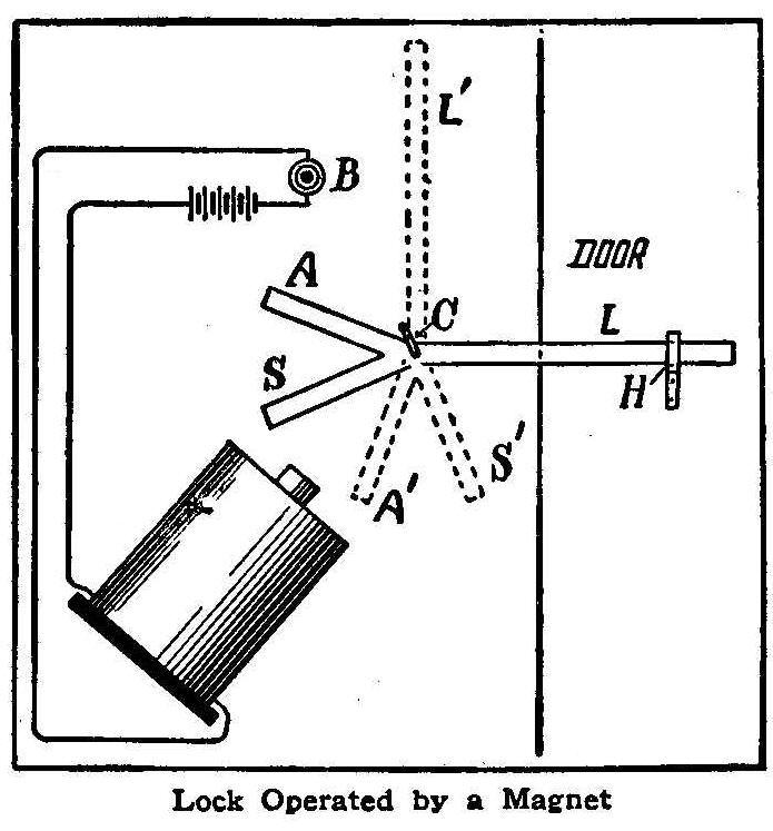
Lock Operated by a Magnet
The illustration shows an automatic lock operated by electricity,
requiring a strong magnet, but no weights or strings, which
greatly simplifies the device over many others of the kind.
The weight of the long arm, L, is just a trifle greater than the
combined weights of the short arms, A and S. The fulcrum of the
lever is at C, where there is a staple. The lever swings on one
arm of the staple and the other arm is so placed that when the
lever is in an upright position, with the long arm at L’, it will
not fall because of its greater weight but stays in the position
shown. The purpose of this is to leave the short arm, A, when in
position at A’, within the reach of the magnet. Arm L rests on an
L-shaped hook, H; in this position the door is locked.
To unlock the door, press the button, B. The momentum acquired
from the magnet by the short arms, A and S, is sufficient to move
the long arm up to the position of L’. To lock the door, press
the button and the momentum acquired from the magnet by the short
arms, now at A’ and S’, is sufficient to move the long arm down
from L’ to the position at L.
Contributed by Benjamin Kubelsky, Chicago.
Direct-Connected Reverse for Small Motors
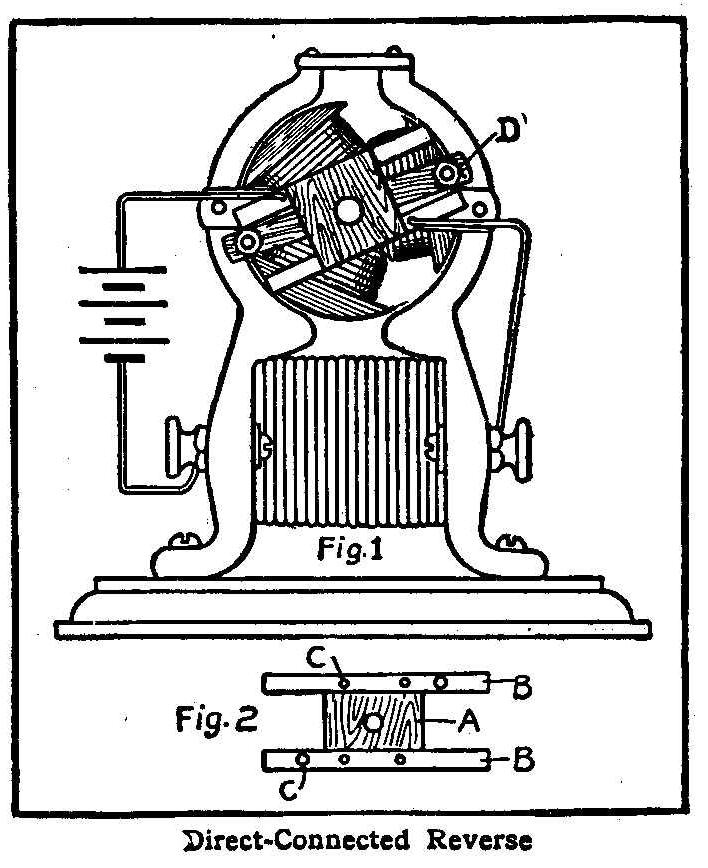
Direct-Connected Reverse
A simple reverse for small motors can be attached directly to the
motor as shown in Fig. 1. Fig. 2 shows the construction of the
reverse block: A is a strip of walnut 5/8 in. square and 3/8 in.
thick with strips of brass or copper (BB) attached as shown.
Holes (CC) are drilled for the wire connections and they must be
flush with the surface of the block. A hole for a 1/2 in. screw
is bored in the block. In Fig. 1, D is a thin strip of walnut or
other dense, hard wood fitted to the binding posts of the brush
holders, to receive the screw in the center.
Before putting the reverse block on the motor, remove all the
connections between the lower binding posts and the brush holders
and connect both ends of the field coil to the lower posts. Bend
the strips BB (Fig. 2) to the proper position to make a wiping
contact with the nuts holding the strip of wood D, Fig. 1. Put
the screw in tight enough to make the block turn a little hard.
Connect as shown in the illustration. To reverse, turn the block
so the strips change connections and the motor will do the rest.
Contributed by Joseph B. Keil, Marion, Ohio.
A Handy Ice Chisel
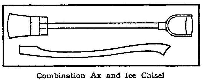
Combination Ax and Ice Chisel
Fishing through the ice is great sport, but cutting the first
holes preparatory to setting the lines is not always an easy
task. The ice chisel here described will be found very handy, and
may be made at very slight expense.
In the top of an old ax-head drill a 9/16-in. hole, and then tap
it for a 3/8-in. gas-pipe, about 18 in. long. Thread the other
end of the pipe, and screw on an old snow-shovel handle. When
ready for use, screw the two pieces together and you have your
chisel complete.
A short ax-handle may be included in the outfit. When the holes
are finished and your lines set, unscrew the pipe from the head
of the ax, put in the handle, and your ax is ready to cut the
wood to keep your fire going.
Contributed by C. J. Rand, West Somerville, Mass.
More Uses for Pipe Fittings
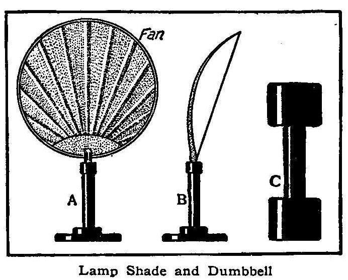
Lamp Shade and Dumbbell
It would seem that the number of useful articles that can be made
from pipes and fittings is unlimited. The sketch shows two more
that may be added to the list. A and B are front and side views
of a lamp-screen, and C is a dumbbell. The lamp shade is
particularly useful for shading the eyes when reading or writing
and, if enameled white on the concave side, makes an excellent
reflector for drawing at night, or for microscopic work.
The standard and base, consisting of an ordinary pipe flange
bushed down to receive the upright nipple, are enameled a jet
black, and if the device is to be used on a polished table, a
piece of felt should be glued to the bottom. A good way to hold
the fan in the nipple is to use a small wedge.
The dumbbells are made of short pieces of 3/4-in. pipe with
1-2-in. couplings fastened to each end by pouring
melted lead in
the space between the pipes and the couplings. The appearance is
greatly improved by enameling black, and if desired the handles
may be covered with leather.
Contributed by C. E. Warren, M. D., North Easton, Mass.
Sealing-Wax Bent While Cold
Bending Cold Sealing-Wax
If a piece of sealing-wax is supported in a horizontal position
by one end, as shown at A in the sketch, it will gradually bend
to the shape indicated by the dotted lines B. To attempt bending
it with the hands would result in breaking it unless a steady
pressure were applied for a long time. This peculiar property is
also found in ice.
Homemade Pottery Kiln
Homemade Pottery Kiln
A small kiln for baking clay figures may be built at a cost of
$1. The following shows the general plan of such a kiln which has
stood the test of 200 firings, and which is good for any work
requiring less than 1400° C.
Get an iron pail about 1 ft. high by 1 ft. across, with a cover.
Any old pail which is thick enough will do, while a new one will
cost about 80 cents. In the bottom of this cut a 2-in. round hole
and close it with a cork or wood plug, A, Fig. 1, which shall
project at least 2 in. inside the pail. Make a cylindrical core
of wood, B, Fig. 1, 8 in. long and 8 in. across. Make a mixture
of clay, 60%; sand, 15%; and graphite, 25%, kneading thoroughly
in water to a good molding consistency. Line the pail, bottom and
sides, with heavy paper and cover the core with same. Now pack
the bottom of the pail thoroughly with a 2-in. layer of the clay
mixture, and on it set the paper wrapped core, carefully
centering it. The 2 in. of space between the core and the sides
of the pail all around is to be filled with clay, C, as is shown
in the sketch, using a little at a time and packing it very
tight. In like manner make the cover of the kiln, cutting the
hole a little smaller, about 1 in. At the edge or rim of the
cover encircle a 2-in. strip of sheet iron, E, Fig. 2, to hold
the clay mixture, C. Set aside for a few days until well dried.
While these are drying you may be making a muffle, if there is to
be any glazing done. This is a clay cylinder (Fig. 3) with false
top and bottom, in which the pottery to be glazed is protected
from any smoke or dust. It is placed inside the kiln, setting on
any convenient blocks which will place it midway. The walls of
the muffle should be about 1/2 in. thick, and the dimensions
should allow at least 1 in. of space all around for the passage
of heat between it and the walls of the kiln. By the time the
clay of the kiln is well dried, it will be found that it has all
shrunk away from the iron about 3/8 in. After removing all the
paper, pack this space-top, bottom and sides-with moist ground
asbestos.
If the cover of the pail has no rim, it may be fastened
to the asbestos
and clay lining by punching a few holes, passing
wire nails through and clinching them. Fit all the parts together
snugly, take out the plugs in the top and bottom, and your kiln
is ready for business. The handle of the pail will be convenient
for moving it about, and it can be set on three bricks or some
more elaborate support, as dictated by fancy and expense.
The temperature required for baking earthenware is 1250°-1310°,
C.; hotel china, 1330°; hard porcelain, 1390°-1410°. These
temperatures can not be obtained in the above kiln by means of
the ordinary Bunsen burner. If will be necessary either to buy
the largest size Bunsen, or make one yourself, if you have the
materials. If you can get a cone which can be screwed into an
inch pipe, file the opening of the cone to 1/16 in. diameter, and
jacket the whole with a 2-1/2-in. pipe. The flame end of this
burner tube should be about 4-1/2 in. above the cone opening and
should be covered with gauze to prevent flame from snapping back.
When lighted, the point of the blue flame, which is the hottest
part, should be just in the hole in the bottom of the kiln. Such
a burner will be cheaply made and will furnish a kiln temperature
of 1400 degrees, but it will burn a great deal of gas.
A plumber’s torch of medium size will cost more in the beginning,
but will be cheaper in operation. Whatever burner is used, the
firing should be gradual, and with especial caution the first
time. By experiment you will find that a higher temperature is
obtained by placing a 1-in. pipe 2-ft. long over the lid hole as
a chimney. It would be still more effective to get another iron
pail, 2 in. wider than the kiln, and get a down draft by
inverting it over the kiln at whatever height proves most
suitable.
G. L. W.
How to Make a Small Medical Induction Coil
Medical Induction Coil
The coil to be described is 3-1/2 in., full length of iron core,
and 3/4 in. in diameter.
Procure a bundle of small iron wire, say 1/4 in. in diameter, and
cut it 3-1/2 in. long; bind neatly with coarse thread and file
the ends smooth (Fig. 1). This done, make two wood ends, 1-1/4 by
1-1/4 in. and 3/8 in. thick, and varnish. Bore holes in the
center of each so the core will fit in snugly and leave about 1/4
in. projecting from each end (Fig. 1).
After finishing the core, shellac two layers of thick paper over
it between the ends; let this dry thoroughly. Wind two layers of
bell magnet wire over this, allowing several inches of free wire
to come through a hole in the end. Cover with paper and shellac
as before.
Wind about 1/8 in. of fine wire, such as used on telephone
generators, around the coil, leaving long terminals. Soak the
whole in melted paraffin and let cool; bind tightly with black
silk.
The vibrator is made of a piece of thin tin to which is soldered
the head of an iron screw and on the other side a small piece of
platinum, which can be taken from an old electric bell (Fig. 2).
Of course, a regulator must be had for the vibrator; this can be
accomplished by bending a stout piece of copper wire as shown.
The connections and the base for setting up are shown in the
figures.
Contributed by J. T. R., Washington, D. C.
Mechanical Trick With Cards
Card Trick
The following mechanical card trick is easy to prepare and simple
to perform:
First, procure a new deck, and divide it into two piles, one
containing the red cards and the other the black ones, all cards
facing the same way. Take the red cards, square them up and place
in a vise. Then, with a plane, plane off the upper right hand
corner and lower left hand corner, as in Fig. 1, about 1/16 in.
Then take the black cards, square them up, and plane off about
1/16 in. on the upper left hand corner and lower right hand
corner, as in Fig. 2.
Next restore all the cards to one pack, taking care to have the
first card red, the next black, and so on, every alternate card
being the same color. Bend the pack so as to give some spring to
the cards, and by holding one thumb on the upper left-hand corner
all the cards will appear red to the audience; place thumb in the
center at top of pack and they will appear mixed, red and black;
with thumb on upper right-hand corner all cards appear black. You
can display either color called for.
Contributed by Ralph Gingrich, Chicago.
How to Make a Rain Gauge
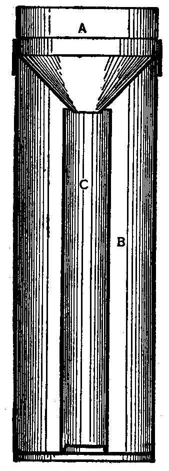
Rain Gauge
An accurate rain gauge may be easily constructed from galvanized
iron, as shown in the sketch herewith. The funnel, A, overlaps
and rests on the body, B, and discharges into the tube, C, the
area of which is one-tenth that of the top of the funnel. The
depth of the water in C is thus ten times the actual rainfall, so
that by measuring it with a stick marked off in tenths of an
inch, we obtain the result in hundredths of an inch.
A good size to make the rain gauge is as follows: A, 8 in.
diameter; C, 2.53 in.; length of C, about 20 in. It should be
placed in an exposed location, so that no inaccuracy will occur
from wind currents. To find the fall of snow, pour a known
quantity of warm water on the snow contained in the funnel and
deduct the quantity poured in from the total amount in the tube.
Contributed by Thurston Hendrickson, Long Branch, N.J.
How to Make an Aquarium
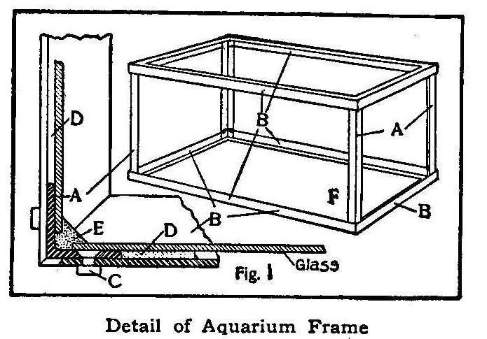
Detail of Aquarium Frame
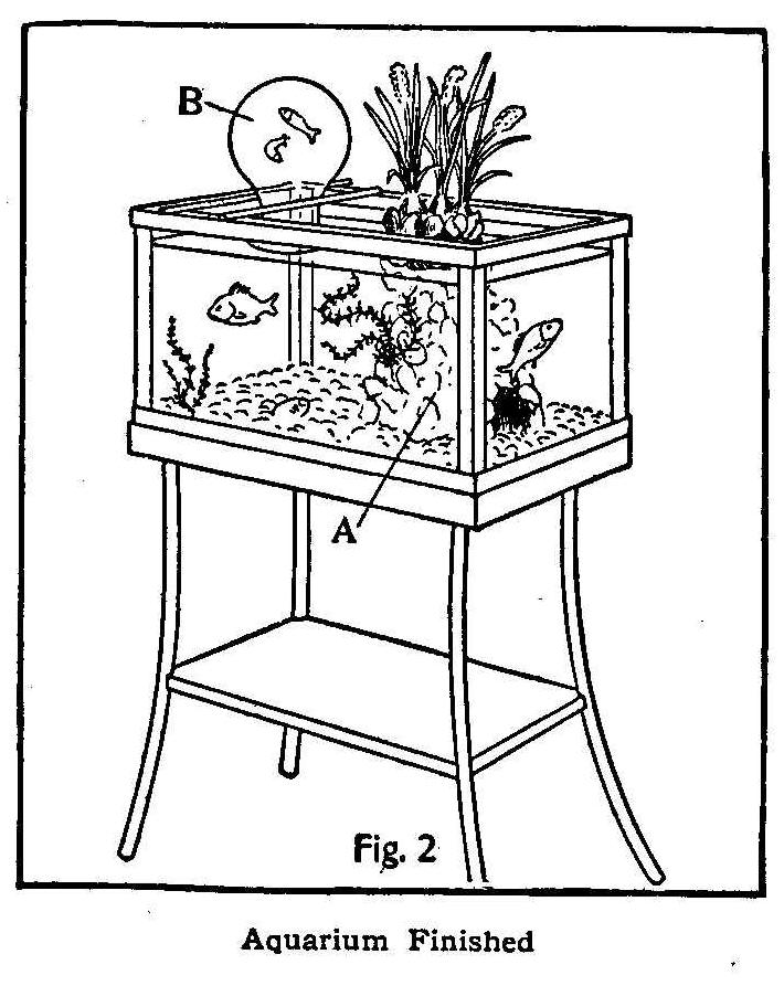
Aquarium Finished
In making an aquarium, the first thing to decide on is the size.
It is well not to attempt building a very large one, as the
difficulties increase with the size. A good size is 12 by 12 by
20 in., and this is inexpensive to build. First buy one length of
3/4 by 1/8-in. angle iron for the frame, F, Fig. 1. This can be
obtained at any steel shop and should cost about 20 cents. All
the horizontal pieces, B, should be beveled 45° at the ends and
drilled for 3/16 in. stove bolts. The beveling may be done by
roughing out with a hacksaw and finishing with a file. After all
the pieces are cut and beveled they should be drilled at the ends
for the 3/16-in. stove bolts, C. Drill all the horizontal pieces,
B, first and then mark the holes on the upright pieces, A,
through the holes already drilled, thus making all the holes
coincide. Mark the ends of each piece with a figure or letter, so
that when they are assembled, the same ends will come together
again. The upright pieces, A, should be countersunk as shown in
the detail, and then the frame is ready to assemble.
After the frame has been assembled take it to glazier and have a
bottom made of skylight glass, and sides and ends of double-thick
window glass. The bottom glass should be a good fit, but the
sides and ends should be made slightly shorter to allow the
cement, E, to form a dovetail joint as shown. When the glass is
put in the frame a space, D, will be found between the glass and
the horizontal pieces, B, of the frame. If this were allowed to
remain the pressure of the water would spring the glass and cause
a leak at E; so it is filled up with plaster of paris.
The cement, E, is made as follows: Take 1 gill of plaster of
paris, 1 gill of litharge (lead monoxide),
1 gill of fine white sand, and 1/3 of
a gill of finely powdered rosin. Mix well and add boiled linseed
oil and turpentine until as thick as putty. Let the cement dry
three or four days before putting any water in the aquarium.
In choosing stock for the aquarium it should be remembered that a
sufficient quantity of vegetable life is required to furnish
oxygen for the fish. In a well balanced aquarium the water
requires renewal only two or three times a year. It is well to
have an excess of plants and a number of snails, as the snails
will devour all the decaying vegetable matter which would
otherwise poison the water and kill the fish.
If desired, a centerpiece (A, Fig. 2) can be made of colored
stones held together by cement, and an inverted jar can be
supported in the position shown at B. If the mouth of the jar is
below the surface of the water it will stay filled and allow the
fish to swim up inside as shown. Some washed pebbles or gravel
should be placed on the bottom, and, if desired, a few Chinese
lilies or other plants may be placed on the centerpiece.
Homemade Pneumatic Lock
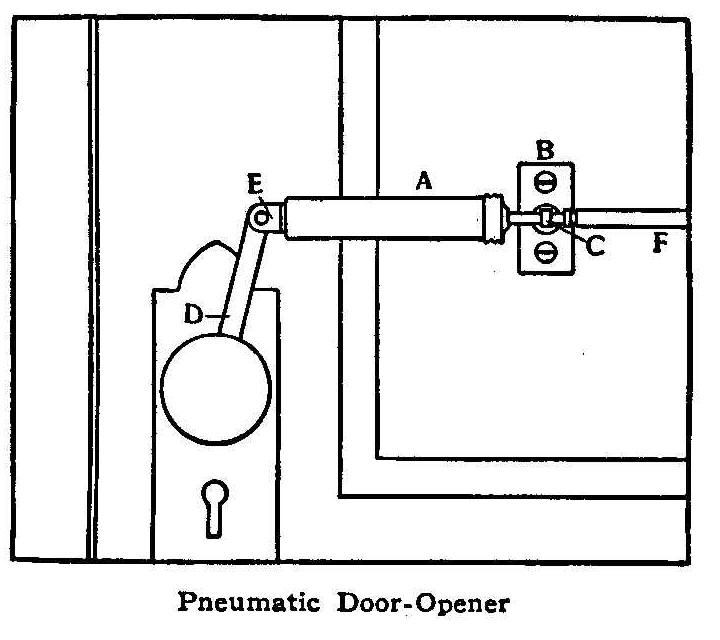
Pneumatic Door-Opener
Mount an old bicycle hand-pump, A, on the door by means of a
metal plate, B, having a swinging connection at C. Fasten the
lever, D, to the door knob, and make a hinge connection with the
pump by means of a piece of sheet brass, E, soldered to the end
of the cylinder. All this apparatus is on the inside of the door
and is connected by a small rubber tube, F, to a secret
mouthpiece placed at some convenient location. A small piece of
spring brass, screwed to the door frame, will open the door about
1/2 in. when the operator blows in the mouthpiece, or if the door
is within reach of the mouthpiece, the operator may push the door
at the same time that he blows, thus doing away with the spring,
which is only used to keep the door from relocking.
One way of making the air connection with the outside is to bend
the tube F around and stick it through the keyhole. Few burglars
would ever think to blow in the keyhole.
Contributed by Orton E. White, Buffalo, N. Y.
A Homemade Water Motor
By Mrs. Paul S. Winter
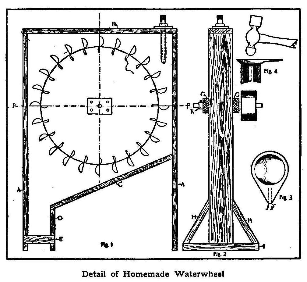
Detail of Homemade Waterwheel
In these days of modern improvements, most houses are equipped
with a washing machine, and the question that arises in the mind
of the householder is how to furnish the power to run it
economically. I referred this question to my husband, with the
result that he built a motor which proved so very satisfactory
that I prevailed upon him to give the readers of Amateur
Mechanics a description of it, hoping it may solve the same
question for them.
A motor of this type will develop about 1/2 hp. with a water
pressure of 70 lb. The power developed is correspondingly
increased or decreased as the pressure exceeds or falls below
this. In the latter case the power may be increased by using a
smaller pulley. Fig. 1 is the motor with one side removed,
showing the paddle-wheel in position; Fig. 2 is an end view; Fig.
3 shows one of the paddles, and Fig. 4 shows the method of
shaping the paddles. To make the frame, several lengths of
scantling 3 in. wide by 1 in. thick (preferably of hard wood) are
required. Cut two of them 4 ft. long, to form the main supports
of the frame, AA, Fig. 1; another, 2 ft. 6 in. long, for the
top, B, Fig. 1; another, 26 in. long, to form the slanting part,
C, Fig. 1; and another, D, approximately 1 ft., according to the
slant given C. After nailing these together as shown in the
illustration, nail two short strips on each side of the outlet,
as at E, to keep the frame from spreading.
Cut two pieces 30 in. long. Lay these on the sides of the frame
with their center lines along the line FF, which is 15 in. from
the outside top of the frame. They are shown in Fig. 2 at GG. Do
not fasten these boards now, but mark their position on the
frame. Two short boards 1 in. wide by 1 in. thick (HH, Fig. 2)
and another 1 in. by 1-1/2 in. (I, Fig. 2) form a substantial
base.
Cut the wheel from sheet iron 1/16 in. thick, 24 in. in diameter.
This can be done roughly with hammer and chisel and then smoothed
up on an emery wheel, after which cut 24 radial slots 3/4 in.
deep on its circumference by means of a hacksaw. On each side of
the wheel at the center fasten a rectangular piece of 1/4-in.
iron 3 by 4 in. and secure it to the wheel by means of four
rivets; after which drill a 5/8 in. hole through the exact center
of the wheel.
Cut 24 pieces of 1/32-in. iron, 1-1/2 by 2-1/2 in. These are the
paddles. Shape them by placing one end over a section of 1-in.
pipe, and hammer bowl shaped with the peen of a hammer, as shown
in Fig. 4. Then cut them into the shape shown in Fig. 3 and bend
the tapered end in along the lines JJ, after which place them in
the slots of the wheel and bend the sides over to clamp the
wheel. Drill 1/8-in. holes through the wheel and sides of the
paddles and rivet paddles in place. Next secure a 5/8-in. steel
shaft 12 in. long to the wheel about 8 in. from one end by means
of a key. This is done by cutting a groove in the shaft and a
corresponding groove in the wheel and fitting in a piece of metal
in order to secure the wheel from turning independently of the
shaft. Procure two collars or round pieces of brass (KK, Fig. 2)
with a 5/8-in. hole through them, and fasten these to the shaft
by means of set screws to prevent it from moving lengthwise.
Make the nozzle by taking a piece of 1/2-in. galvanized pipe
3-1/2 in. long and filling it with babbitt metal; then drill a
3/16-in. hole through its center. Make this hole conical,
tapering from 3/16 in. to a full 1/2 in. This is best done by
using a square taper reamer. Then place the nozzle in the
position shown in Fig. 1, which allows the stream of water to
strike the buckets full in the center when they reach the
position farthest to the right.
Take the side pieces, GG, and drill a 1-in. hole through their
sides centrally, and a 1/4-in. hole from the tops to the 1-in.
holes. Fasten them in their proper position, with the wheel and
shaft in place, the shaft projecting through the holes just
mentioned. Now block the wheel; that is, fasten it by means of
wedges or blocks of wood until the shaft is exactly in the center
of the inch holes in the side pieces. Cut four disks of cardboard
to slip over the shaft and large enough to cover the inch holes.
Two of these are to be inside and two outside of the frames (one
to bear against each side of each crosspiece). Fasten these to
the crosspieces by means of tacks to hold them securely. Pour
melted babbitt metal into the 1/4-in. hole to form the bearings.
When it has cooled, remove the cardboard, take down the
crosspieces, and drill a 1/8-in. hole from the top of the
crosspieces through the babbitt for an oil-hole.
Secure sufficient sheet zinc to cover the sides of the frame. Cut
the zinc to the same shape as the frame and let it extend down to
the crosspieces EE. Tack one side on. (It is well to tack strips
of heavy cloth—burlap will do—along the edges under the
zinc to form a water-tight joint.) Fasten the crosspiece over the
zinc in its proper position. Drill a hole through the zinc, using
the hole in the crosspiece as a guide. Then put the wheel in a
central position in the frame, tack the other side piece of zinc
in place and put the other crosspiece in place. Place the two
collars mentioned before on the shaft, and fasten so as to bear
against the crosspieces, in order to prevent the wheel and shaft
from moving sidewise. If the bearings are now oiled, the shaft
should turn easily and smoothly. Fasten a pulley 4 or 6 in. in
diameter to the longest arm of the shaft. Connect the nozzle to a
water faucet by means of a piece of hose; place the outlet over a
drain, and belt the motor direct to the washing-machine, sewing
machine, ice-cream freezer, drill press, dynamo or any other
machinery requiring not more than 1/2 hp.
This motor has been in use in our house for two years in all of
the above ways, and has never once failed to give perfect
satisfaction. It is obvious that, had the wheel and paddles been
made of brass, it would be more durable, but as it would have
cost several times as much, it is a question whether it would be
more economical in the end. If sheet-iron is used, a coat of
heavy paint would prevent rust and therefore prolong the life of
the motor. The motor will soon pay for itself in the saving of
laundry bills. We used to spend $1 a month to have just my
husband’s overalls done at the laundry, but now I put them in the
machine, start the motor, and leave them for an hour or so. At
the end of this time they are perfectly clean, and I have noticed
that they wear twice as long as when I sent them to the laundry.
How to Make Silhouettes

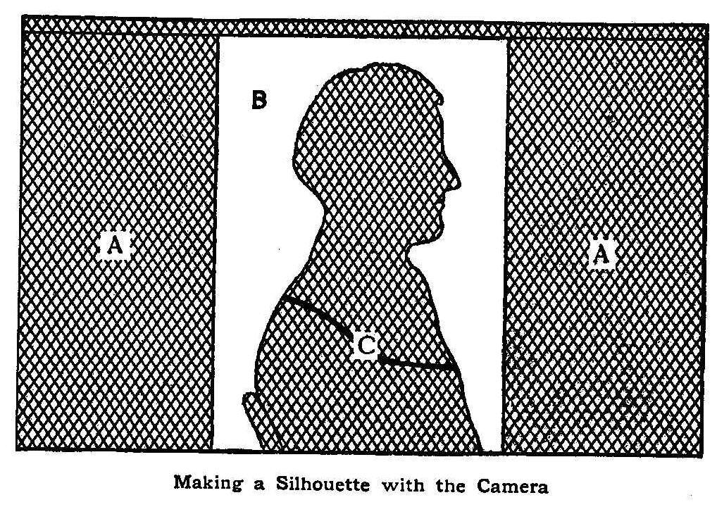
Making a Silhouette with the Camera
Photography in all branches is truly a most absorbing occupation.
Each of us who has a camera is constantly experimenting, and
everyone of us is delighted when something new is suggested for
such experiments.
To use a camera in making silhouettes select a window facing
north if possible, or if used only at times when the sun is not
on it, any window will do, says the Photographic Times. Raise the
window shade half way, remove any white curtains there may be,
and in the center of the lower pane of glass paste by the four
corners a sheet of tissue paper that is perfectly smooth and
quite thick, as shown in the sketch at B. Darken the rest of the
window, shutting out all light from above and the sides. Place a
chair so that after being seated the head of the subject will
come before the center of the tissue paper, and as near to it as
possible, and when looking straight before him his face will be
in clear profile to the camera.
Draw the shades of all other windows in the room. Focus the
camera carefully, getting a sharp outline of the profile on the
screen. Do not stop down the lens, as this makes long exposure
necessary, and the subject may move.
Correct exposure depends, of course, on the lens, light and the
plate. But remember that a black and white negative is wanted
with as little detail in the features as possible. The best plate
to use is a very slow one, or what is called a process plate.
In developing get all possible density in the high lights,
without detail in the face, and without fog. Printing is best
done on contrasty development paper with developer not too
strong.
The ideal silhouette print is a perfectly black profile on a
white ground. With a piece of black paper, any shape in stopping
off print may be made as shown at C in the sketch.
How to Make a Galvanoscope
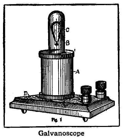
Galvanoscope
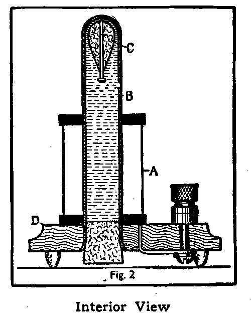
Interior View
A galvanoscope for detecting small currents of electricity can be
made from a coil of wire, A; a glass tube, B, full of water; a
core, C; and a base, D, with binding posts as shown. The core C,
which is made of iron and cork, is a trifle lighter than the
water it displaces and will therefore normally remain in the top
of the tube; but as soon as a current of electricity passes
through the coil, the core is drawn down out of sight. The
current required is very small, as the core is so nearly balanced
that the least attraction will cause it to sink.
The glass tube may be a test tube, as shown in Fig. 2, or an
empty developer tube. If one has neither a test tube nor
developer tube, an empty pill bottle may be used. The washers at
the ends of the coil can be made of fiber, hard rubber, or wood;
or can be taken from an old magnet. The base may be made of wood
or any other insulating material and should have four short legs
on the bottom. Make the coil of single-covered wire about No. 18
and connect ends to binding posts as shown in Fig. 2.
The core is made by pushing a small nail through a piece of cork.
It should be made so that it will rise slowly when placed under
water. Some filing may be necessary to get the weight just right,
but it should be remembered that the buoyancy of the core can be
adjusted after the parts are assembled, by pressing the cork in
the bottom of the test tube. This causes compression in the water
so that some is forced into the upper cork, reducing its
displacement and causing it to sink. The lower cork is then
slowly withdrawn, by twisting, until the core slowly rises.
The instrument will then be adjusted ready for use.
Connect the binding posts to a single cell of battery—any kind
will do, as a slight current will answer. On completing the
circuit the core will descend; or put in a switch or push button
on one of the battery wires. If the button be concealed where the
operator can reach it, the core will obey his command to rise or
fall, according to his control of the current. This is a
mysterious looking instrument, the core being moved without
visible connection to any other part.
Lubricating Sheet Metal
To lubricate sheet metal mix 1 qt. whale oil, 1 lb.
white lead, 1 pt. water and 3 oz. finest
graphite. Apply with a brush before the metal enters the dies.
An Optical Top
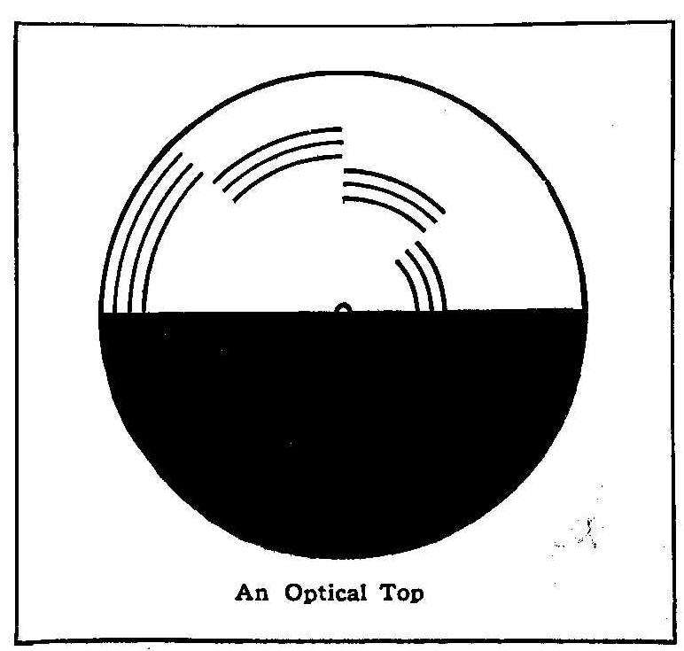
An Optical Top
One of the latest optical delusions, and one not easy to explain,
is Benham’s color top. Cut out the black and white disk shown in
the figure, and paste on a piece of stiff cardboard. Trim the
edges of the cardboard to match the shape of the disk, and make a
pinhole in the center. Cut the pin in half and push it through
from the under side until the head of the pin touches the
cardboard. Spin slowly in a strong light and some of the lines
will appear colored. The colors appear different to different
people, and are changed by reversing the rotation.
Card Trick with a Tapered Deck
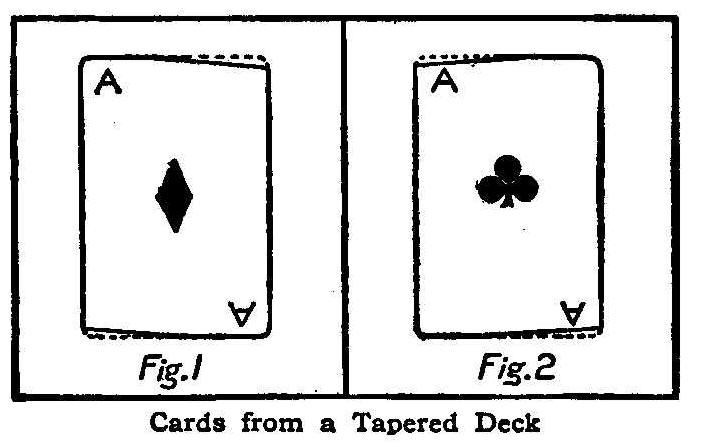
Cards from a Tapered Deck
Another simple trick to perform but one not easily detected, is
executed by using a tapered deck of cards as shown in Fig. 1. A
cheap deck of cards is evened up square, fastened in a vise and
planed along the edge in such a manner that all the pack will be
tapered about 1/16 in. This taper is exaggerated in the
illustration which shows one card that has been turned end for
end.
It is evident that any card reversed in this way can be easily
separated from the other cards in the pack, which makes it
possible to perform the following trick: The performer spreads
the cards out, fan-like, and asks an observer to withdraw a card,
which is then replaced in any part of the pack. After thoroughly
shuffling the cards the performer then holds the deck in both
hands behind his back and pronouncing a few magic words, produces
the card selected in one hand and the rest of the pack in the
other. This is accomplished by simply turning the deck end for
end while the observer is looking at his card, thus bringing the
wide end of the selected card at the narrow end of the pack when
it is replaced. The hands are placed behind the pack for a double
purpose, as the feat then seems more marvelous and the observers
are not allowed to see how it is done.
In prize games, players having the same score are frequently
called upon to cut for low to determine which shall be the
winner, but a fairer way is to cut for high as a person familiar
with the trick shown in Fig. 2 can cut the cards at the ace,
deuce, or three spot, nearly every time, especially if the deck
is a new one. This is done by simply pressing on the top of the
deck as shown, before cutting, thus causing the increased ink
surface of the high cards to adhere to the adjacent ones. A
little practice will soon enable one to cut low nearly every
time, but the cards must be grasped lightly and the experiment
should be performed with a new deck to obtain successful results.
Contributed by D.B.L., Chicago.
A Constant-Pressure Hydrogen Generator
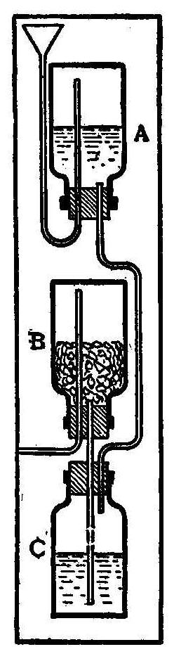
By fitting three bottles, A, B, C, with rubber stoppers and
connecting with glass tubes as shown in the sketch,
hydrogen or
other gases produced in a similar manner may be generated under
constant pressure. In making hydrogen,
bottle B is partly filled
with zinc nodules formed by slowly pouring melted zinc into
water. Hydrochloric acid is then poured in the small funnel, thus
partly filling bottles A and C. When the acid rising from C comes
in contact with the zinc, hydrogen
gas is generated and fills
bottle B. The gas continues to generate until the pressure is
sufficient to force the acid back down the tube into bottle C,
when the action ceases. As fast as the gas is used the acid rises
in the tube and generates more, thus keeping the pressure nearly
constant, the pressure depending on the difference between the
levels of the acid in bottle A and bottle B. As this device is
easily upset, a ring-stand should be used to prevent its being
broken, or if it is to be a permanent apparatus it may be mounted
on a substantial wooden base. This apparatus may also be used for
preparing acetylene
gas or almost any gas which requires a
mixture of a solid and liquid in its preparation.
Contributed by C. S. J., Detroit.
[Transcriber’s note: I recall doing this experiment in a college
chemistry lab. The instructor warned us to drape the experiment
with a cloth before adding the acid. Ten minutes later there
began a series of small explosions throughout the lab.]
Restoring Tone to a Cracked Bell
Many a bell with a deadened tone due to a cracked rim, can be
given its original clear ringing sound by sawing out the crack
with a common hacksaw. Make the saw cut along the line of the
crack. The opening caused by the saw will allow the free
vibration of the metal.
Contributed by F. W. Bently, Jr., Huron, S. Dak.
How to Make a Paper Phonograph Horn
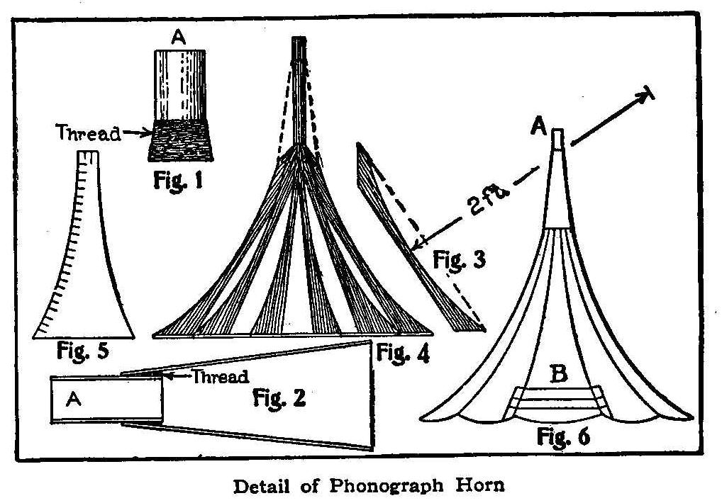
Detail of Phonograph Horn
Secure a piece of tubing about 1-3/4 in. long that will fit the
connection to the reproducer, and wrap a quantity of heavy thread
around one end as shown in the enlarged sketch A, Fig. 1. Form a
cone of heavy paper, 9 in. long and 3 in. in diameter, at the
larger end with the smaller end to fit the diameter of the tube
A, making it three-ply thick and gluing the layers together.
Attach this cone on the tube A where the thread has been wrapped
with glue, as shown in Fig. 2. Fig. 2 is also an enlarged sketch.
Make ten pieces about 1 ft. 10 in. in length and 3 in. wide from
the thin boards of a biscuit or cracker box. Cut an arc of a
circle in them on a radius of 2 ft. (Fig. 3). Make a 10-sided
stick, 12 in. long, that will fit loosely in the tube A, to which
nail the 10 pieces as shown in Fig. 4, connecting the bottom by
cross pieces, using care to keep them at equal distances apart
and in a circle whose diameter is about 2 ft.
The cone is placed over the stick as shown by the dotted lines in
Fig. 4 and temporarily fastened in position. Cut out paper
sections (Fig. 5) that will cover each space between the 10
pieces, allowing 1 in. on one side and the top, in which to cut
slits that will form pieces to overlap the next section and to
attach with glue. Fasten the sections all around in like manner.
The next course is put on in strips overlapping as shown at B,
Fig. 6. Finish by putting on sections in the same way as the
first course, making it three-ply thick. Remove the form, trim to
suit and glue a piece of paper over the edge. When the glue is
thoroughly hardened, put on two coats of white and one of blue
paint, shading it to suit and striping it with gold bronze.
How to Make a Hygrometer
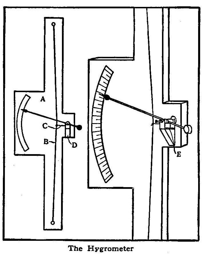
The Hygrometer
A homemade hygrometer, for determining the degree of moisture in
the atmosphere, is shown in the accompanying sketch and consists
of a board, A, with a nail at each end to hold the silk thread B.
A second piece of silk thread, C, is tied to the center of B and
connects with an indicating hand or pointer supported by the
bracket D. The axle on which the pointer revolves consists of a
piece of round wood, about the size of a lead-pencil, with a pin
driven in each end. A piece of tin, E, is cut V-shaped at each
end and bent up at the ends to form bearings for the pins. The
silk thread C is fastened to the wooden axle and is wrapped one
or two turns around it, so that when the thread is pulled the
pointer will move on the scale. It will be noticed that the
thread B is not perfectly straight, but bends toward D. For this
reason a very small shrinkage of B, such as occurs when the
atmosphere is dry, will cause an increased movement of C, which
will be further increased in the movement of the pointer. An
instrument of this kind is very interesting and costs nothing to
make.
Contributed by Reader, Denver.
The Protection of a Spring Lock
After shutting the front door and hearing the spring lock snap
into its socket, most people go off with a childlike faith in the
safety of their goods and chattels. But the cold fact is that
there is scarcely any locking device which affords less
protection than the ordinary spring lock. It is the simplest
thing in the world for a sneak thief to slip a thin knife between
the door-casing and the strip, push back the bolt, and walk in.
Fortunately, it is equally easy to block that trick. Take a
narrow piece of tin 3 or 4 in. long, bend it at right angles
throughout its length, and tack it firmly in the angle between
the casing and strip, so as to make it impossible to reach the
bolt without tearing off the strip.
Another way is to drive nails through the strip at intervals of
half an inch, enough to protect the bolt from being meddled with.
A Controller and Reverse for a Battery Motor
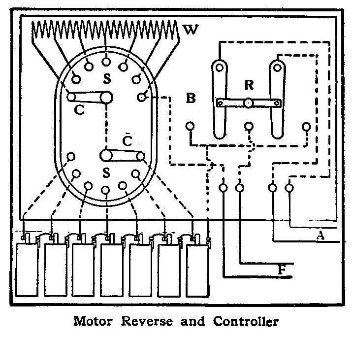
Motor Reverse and Controller
Secure a cigar or starch box and use to make the base, B. Two
wood-base switches, S S, are cut off a little past the center and
fastened to the base with a piece of wood between them. The upper
switch, S, is connected to different equal points on a coil of
wire, W, while the lower switch, S, is connected each point to a
battery, as shown. The reverse switch, R, is made from two brass
or copper strips fastened at the top to the base with screws and
joined together by a piece of hard rubber or wood with a small
handle attached. Connect wires A to the armature and wires F to
the field of the motor. By this arrangement one, two or three and
so on up until all the battery cells are used and different
points of resistance secured on the coil of wire. The reverse
lever when moved from right to left, or left to right, changes
the direction of the armature in the motor from one way to the
other.
Contributed by J. Fremont Hilscher, Jr., West St. Paul, Minn.
How to Build a Grape Arbor

Grape-Arbor Trellis
A grape arbor made of white pine, put together as shown in the
sketch, will last for several years. The 2 by 4-in. posts, A, are
7 ft. long. The feet, B, are made 2 by 4 in., 4 ft. long, and
rest on a brick placed under each end.
How to Make a Toy Steam Engine
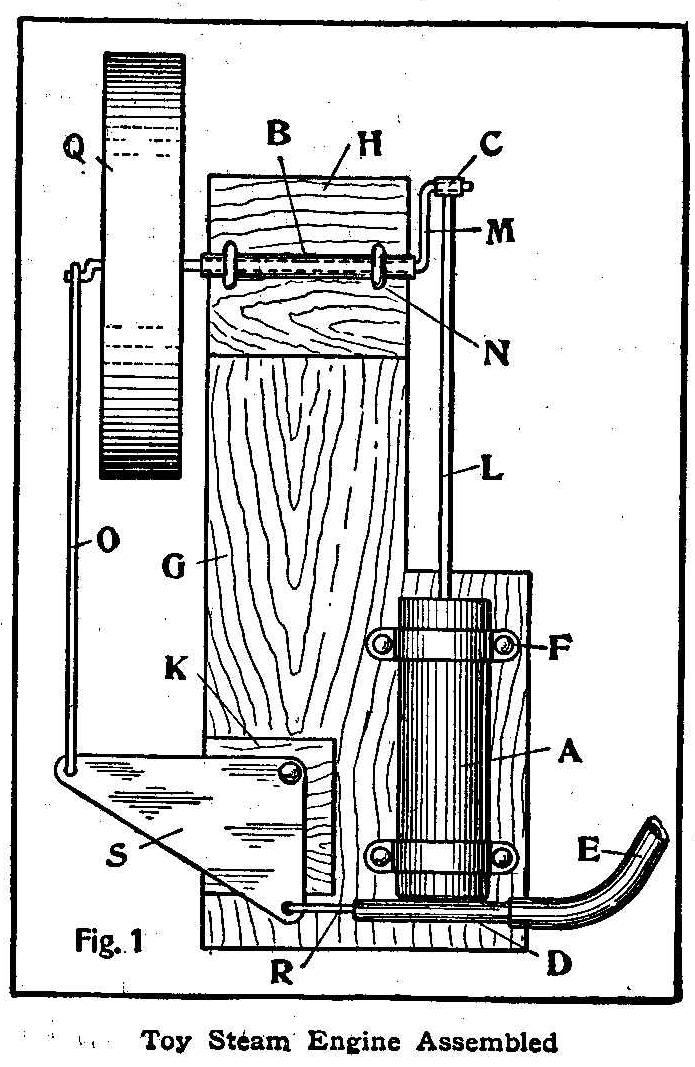
Toy Steam Engine Assembled
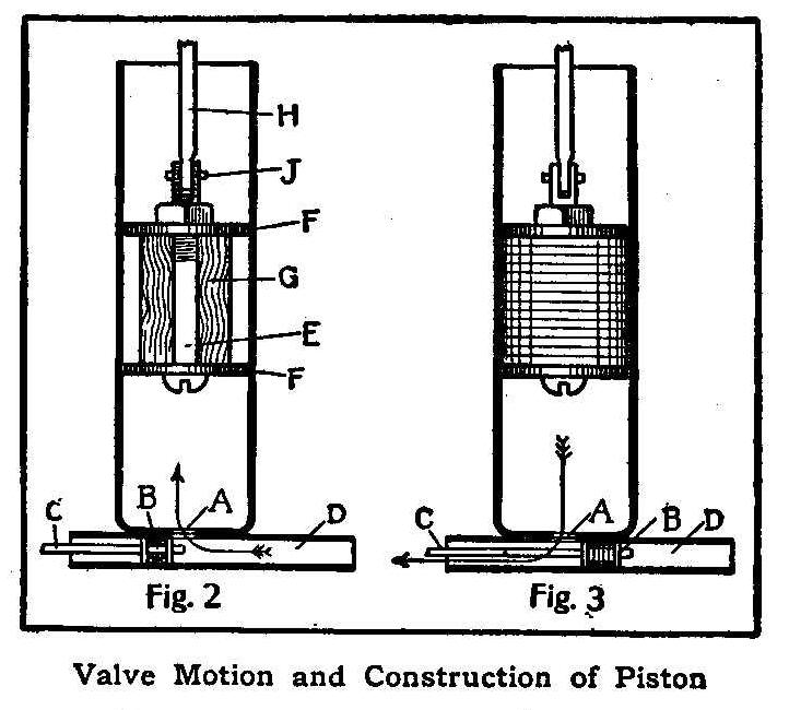
Valve Motion and Construction of Piston
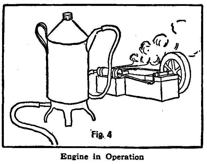
Engine in Operation
A toy engine can be easily made from old implements which can be
found in nearly every house.
The cylinder A, Fig. 1, is an old bicycle pump, cut in half. The
steam chest D, is part of the piston tube of the same pump, the
other parts being used for the bearing B, and the crank bearing
C. The flywheel Q can be any small-sized iron wheel; either an
old sewing-machine wheel, pulley wheel, or anything available. We
used a wheel from an old high chair for our engine. If the bore
in the wheel is too large for the shaft, it may be bushed with a
piece of hard wood. The shaft is made of heavy steel wire, the
size of the hole in the bearing B.
The base is made of wood, and has two wood blocks, H and K, 3/8
in. thick, to support bearing B, and valve crank S, which is made
of tin. The hose E connects to the boiler, which will be
described later. The clips FF are soldered to the cylinder and
nailed to the base, and the bearing B is fastened by staples.
The valve motion is shown in Figs. 2 and 3. In Fig. 2 the steam
is entering the cylinder, and in Fig. 3 the valve B has closed
the steam inlet and opened the exhaust, thus allowing the steam
in the cylinder to escape.
The piston is made of a stove bolt, E, Fig. 2, with two washers,
FF, and a cylindrical piece of hard wood, G. This is wound with
soft string, as shown in Fig. 3, and saturated with thick oil. A
slot is cut in the end of the bolt E, to receive the connecting
rod H. The valve B is made of an old bicycle spoke, C, with the
nut cut in half and filed down as shown, the space between the
two halves being filled with string and oiled.
The valve crank S, Fig. 1, is cut out of tin, or galvanized iron,
and is moved by a small crank on the shaft. This crank should be
at right angles to the main crank.
The boiler, Fig. 4, can be an old oil can, powder can, or a syrup
can with a tube soldered to it, and is connected to the engine by
a piece of rubber tubing. The heat from a small gas stove will
furnish steam fast enough to run the engine at high speed.
This engine was built by W. G. Schuh and A. J. Eustice, of Cuba, Wis.
Writing with Electricity
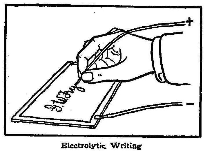
Electrolytic Writing
Soak a piece of white paper in a solution of potassium iodide and
water for about a minute and then lay it on a piece of sheet
metal. Connect the sheet metal with the negative or zinc side of
a battery and then, using the positive wire as a pen, write your
name or other inscription on the wet paper. The result will be
brown lines on a white background.
Contributed by Geo. W. Fry, San Jose, Cal.
To Photograph a Man in a Bottle
Neither a huge bottle nor a dwarfed man is necessary for this
process, as it is merely a trick of photography, and a very
amusing trick, at that.
First, photograph the person to be enclosed in the bottle against
a dark plain background and mark the exact position on the ground
glass. Let the exposure be just long enough to show the figure
distinctly. Then place an empty bottle against a dark background
and focus so as to have the outlines of the bottle enclose those
of the man. Let this exposure be about twice the length of the
first, and the desired result is obtained.
A Musical Windmill
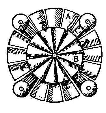
Make two wheels out of tin. They may be of any size, but wheel A
must be larger than wheel B. On wheel A fasten two pieces of
wood, C, to cross in the center, and place a bell on the four
ends, as shown. The smaller wheel, B, must be separated from the
other with a round piece of wood or an old spool. Tie four
buttons with split rings to the smaller wheel, B. The blades on
the wheels should be bent opposite on one wheel from the others
so as to make the wheels turn in different directions. When
turning, the buttons will strike the bells and make them ring
constantly.
Optical Illusions
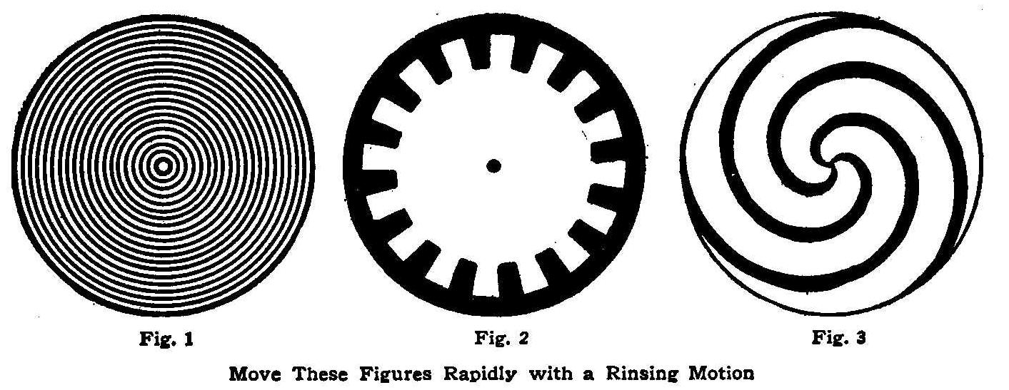
Move These Figures Rapidly with a Rinsing Motion
By giving the page a revolving or rinsing motion the three
circular figures printed on the next page appear to rotate. The
best effect will be produced by laying the book down flat on the
desk or table and revolving, first in one direction and then in
the opposite direction, in such a way that any given point on the
page will describe a circle of about 1/2 in. diameter. Fig. 1
then appears to rotate in the same direction as the revolution;
Fig. 2 appears to revolve in the opposite direction, and Fig. 3
appears to revolve sometimes in the same direction and at other
times in the opposite direction.
A curious effect can be produced with Fig. 1 by covering up Figs.
2 and 3 with a piece of plain paper and laying a coin or other
small object on the paper. If the vision is then concentrated on
the coin or other object while same is being revolved, Fig. 1
will be seen to rotate.
Barrel-Stave Hammock
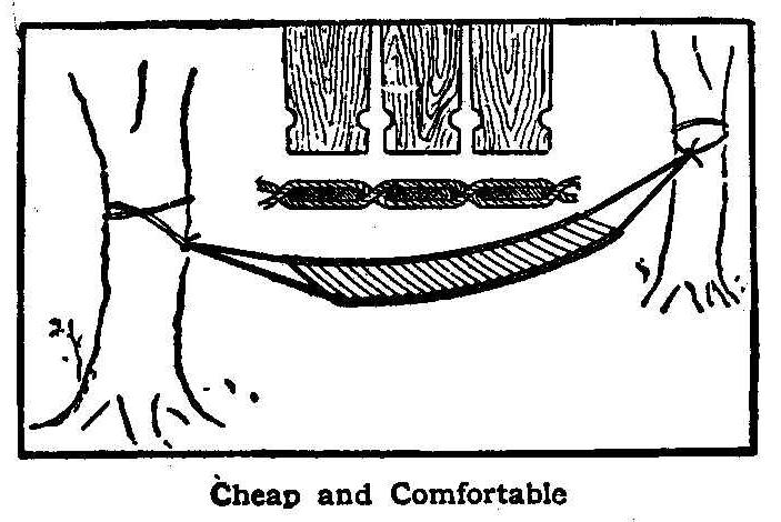
Cheap and Comfortable
A hammock made of barrel staves is more comfortable than one
would think, considering the nature of the material employed in
making it. Good smooth staves should be selected for this
purpose, and if one cares to go to little trouble a thorough
sandpapering will make a great improvement. Cut half circles out
of each stave, as shown at AA, and pass ropes around the ends as
shown at B. When finished the weight will then be supported by
four ropes at each end, which allows the use of small sized
ropes, such as clothes lines. A hammock of this kind may be left
out in the rain without injury.
Contributed by H.G.M., St. Louis, Mo.
A Singing Telephone
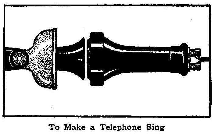
To Make a Telephone Sing
Those who have not already tried the experiment may be interested
to know that a telephone may be made to sing by holding the
receiver about 1/16 in. from the transmitter, as shown in the
illustration. The experiment will work well on most telephones,
but not on all.
When the receiver is placed in the position shown it acts like an
ordinary buzzer, and the function of the transmitter will then be
that of an interrupter. The slightest movement of the
transmitter diaphragm will cause an increased movement of the
receiver diaphragm. This in turn will act on the transmitter,
thus setting up sympathetic vibrations between the two, which
accounts for the sound.
A Microscope Without a Lens
By E. W. Davis
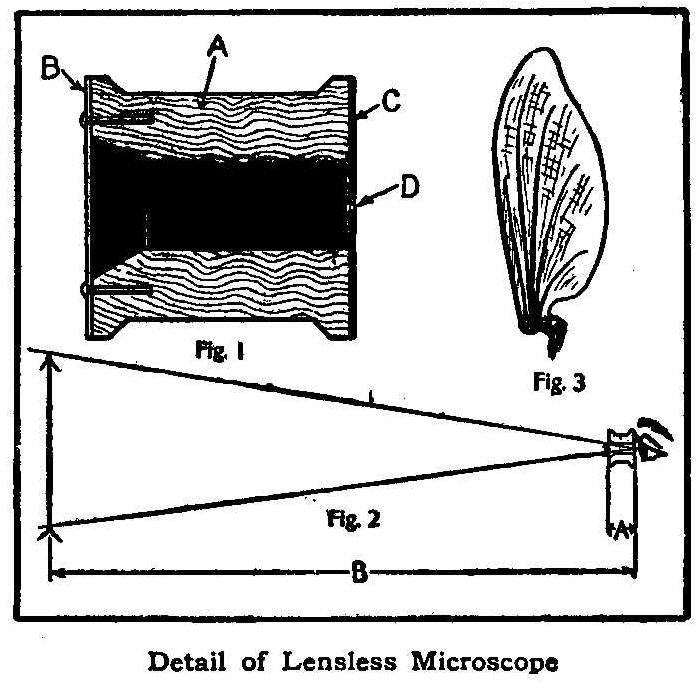
Detail of Lensless Microscope
Nearly everyone has heard of the pin-hole camera, but the fact
that the same principle can be used to make a microscope, having
a magnifying power of 8 diameters (64 times) will perhaps be new
to some readers.
To make this lensless microscope, procure a wooden spool, A (a
short spool, say 1/2 or 3/4 in. long, produces a higher
magnifying power), and enlarge the bore a little at one end. Then
blacken the inside with india ink and allow to dry. From a piece
of thin transparent celluloid or mica, cut out a small disk, B,
and fasten to the end having the enlarged bore, by means of
brads. On the other end glue a piece of thin black cardboard, C,
and at the center, D, make a small hole with the point of a fine
needle. It is very important that the hole D should be very
small, otherwise the image will be blurred.
To use this microscope, place a small object on the transparent
disk, which may be moistened to make the object adhere, and look
through the hole D. It is necessary to have a strong light to get
good results and, as in all microscopes of any power, the object
should be of a transparent nature.
The principle on which this instrument works is illustrated in
Fig. 2. The apparent diameter of an object is inversely
proportional to its distance from the eye, i. e., if the distance
is reduced to one-half, the diameter will appear twice as large;
if the distance is reduced to one-third, the diameter will appear
three times as large, and so on. As the nearest distance at which
the average person can see an object clearly is about 6 in., it
follows that the diameter of an object 3/4 in. from the eye would
appear 8 times the normal size. The object would then be
magnified 8 diameters, or 64 times. (The area would appear 64
times as large.) But an object 3/4-in. from the eye appears so
blurred that none of the details are discernible, and it is for
this reason that the pin-hole is employed.
Viewed through this microscope, a fly’s wing appears as large as
a person’s hand, held at arm’s length, and has the general
appearance shown in Fig. 3. The mother of vinegar examined in the
same way is seen to be swarming with a mass of wriggling little
worms, and may possibly cause the observer to abstain from all
salads forever after. An innocent-looking drop of water, in which
hay has been soaking for several days, reveals hundreds of little
infusoria, darting across the field in every direction. These and
hundreds of other interesting objects may be observed in this
little instrument, which costs little or nothing to make.
How to Make a Telegraph Key and Sounder
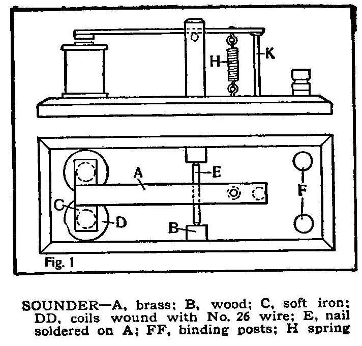
Sounder-A, brass: B, wood: C, soft iron; DD, coils wound with No.
26 wire: E, nail soldered on A; FF, binding posts: H spring
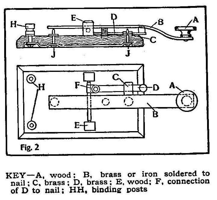
KEY-A, wood; B, brass or iron soldered to nail; C, brass; D,
brass: E, wood: F, connection of D to nail; HH, binding posts
The sounder, Fig. 1, is made from an old electric-bell magnet, D,
fastened to a wooden base. The lever, A, can be made of brass and
the armature, C, is made of iron. The pivot, E, is made from a
wire nail and is soldered to A. It should be filed to a point at
each end so as to move freely in the bearings, B, which are
pieces of hard wood.
The spring, H, is fastened at each end by pins, bent as shown,
and should not be too strong or the magnet will be unable to move
the armature. The stop, K, is a wire nail driven deep enough in
the base to leave about 1/8 in. between the armature and the
magnet. The binding posts, F, may be taken from old dry batteries
and are connected to the two wires from the magnet by wires run
in grooves cut in the base.
The base of the key, Fig. 2, is also made of wood and has two
wooden bearings, E, which are made to receive a pivot, similar to
the one used in the sounder. The lever of the key is made of
brass and has a hardwood knob, A, fastened near the end. A
switch, D, connects with the pivot at F and can be either made
from sheet brass, or taken from a small one-point switch. The
binding posts are like those of the sounder, and are connected to
the contacts, K, by wires run in grooves cut in the wood.
How to Make a Music Cabinet
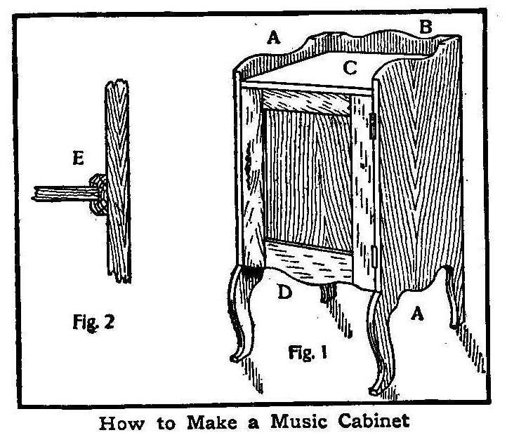
How to Make a Music Cabinet
A neat music cabinet can be made as shown in the accompanying
sketch. Each side, AA, Fig. 1, is cut from a board about 36 in.
in length and 16 in. wide. Both are alike and can be cut from the
same pattern. As the front legs curve out a little the main body
of the boards AA should be 15 in. wide. The back, B, should be
about 22 in. long by 16 in. wide and set in between sides AA. Cut
the top, C, 16 in. long and 14-1/4 in. wide. The bottom must be
the same length as the top and 13-1/2 in. wide.
The door, D, can be made panel as shown, or a single piece, 16
in. wide and about 20 in. long. All material used is to be made
from boards that will dress to 3/4 in. thick.
Shelving may be put in as shown in Fig. 2 and made from 1/4-in.
material. Make 12 cleats, E, 13-1/2 in. long, from a strip of
wood 1/2 by 3/4 in., with a groove 1/4 by 1/4 in. cut in them.
Fasten 6 cleats evenly spaced on the inside of each of the sides,
AA, with 3/4-in. brads. This will give seven spaces for music and
as the shelves are removable two places can be made into one.
Easily Made Wireless Coherer
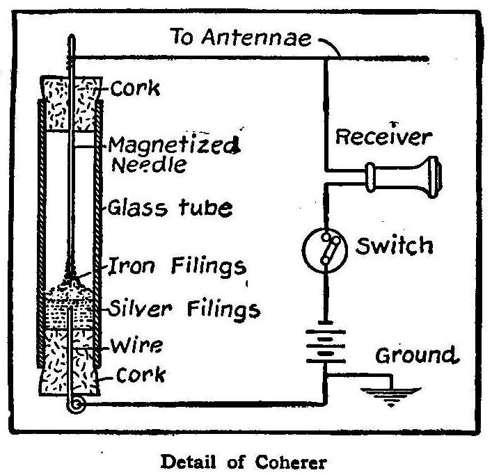
Detail of Coherer
A good wireless coherer may be made with very little expense, the
only materials necessary being a glass tube, two corks: a
magnetized needle and a quantity of iron and silver filings. Push
a piece of wire through one cork and place in the bottom of the
tube, as shown in the sketch.
Pour in the filings and insert the top cork with the needle
pushed through from above. The point of the needle should barely
touch the filings and by slightly agitating the tube the iron
filings will separate from the silver and cling to the magnetized
needle, as shown.
In operation, the device must stand on end and should be
connected in the circuit as shown in the sketch. When the
electrical waves strike the needle, the conductivity of the
filings is established and a click is heard in the receiver.
Contributed by Carl Formhals, Garfield, Ill.
One-Wire Telegraph Line
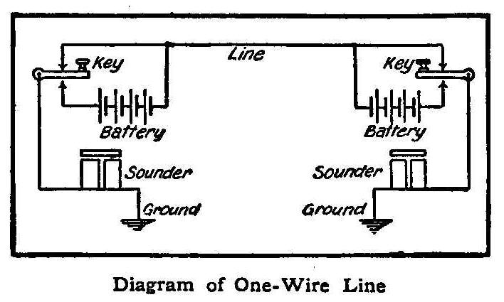
Diagram of One-Wire Line
The accompanying wiring diagram shows a telegraph system that
requires no switches and may be operated with open-circuit
batteries on a one-wire line with ground connections at each end.
Any telegraph set in which the key makes double contact can be
connected up in this way.
Contributed by R. A. Brown, Fairport, N. Y.
How to Make a Water Rheostat
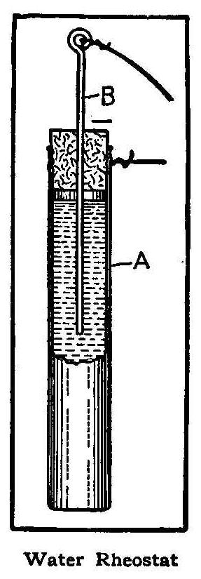
Water Rheostat
A water rheostat may be made by fitting a brass tube with a cork,
through which a piece of wire is passed. The brass tube may be an
old bicycle hand pump, A (see sketch), filled with water. Pushing
the wire, B, down into the water increases the surface in
contact, and thus decreases the resistance. An apparatus of this
kind is suitable for regulating the current from an induction
coil, when the coil is not provided with a regulator, and by
using a piece of pipe instead of the tube, it can be used to
regulate the speed of a motor.
When the pipe is used, a piece of brass or copper rod should be
substituted for the wire, in order to increase the surface.
Adding salt to the water will decrease the resistance, and,
when used with a motor, will give a greater speed.
Contributed by John Koehler, Ridgewood, N. J.
Electric Door-Opener
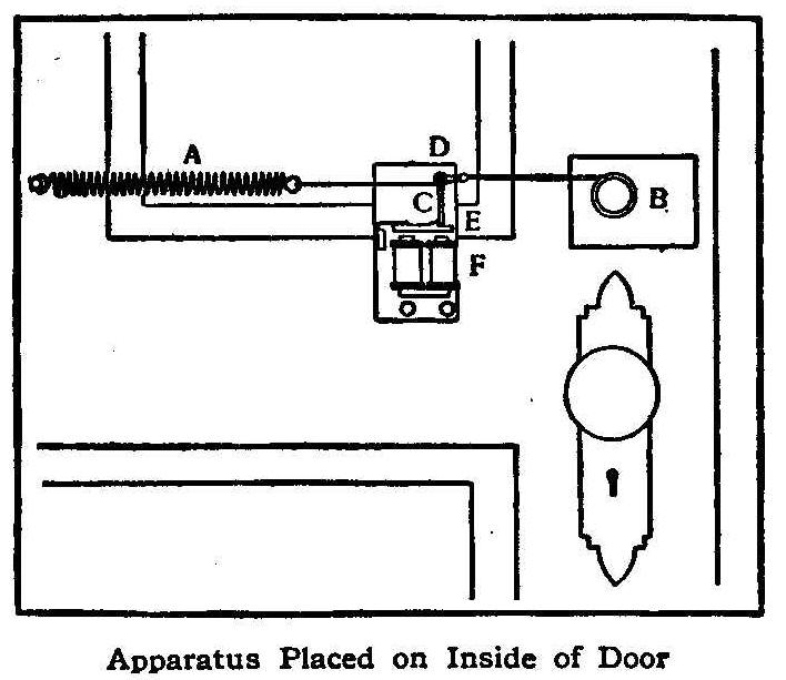
Apparatus Placed on Inside of Door
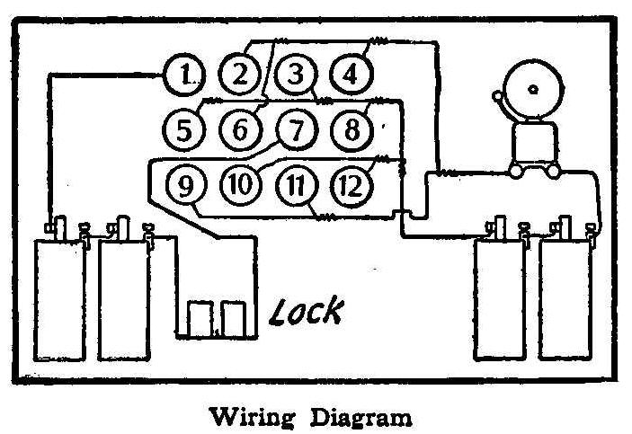
Wiring Diagram
A very convenient and efficient device for unlocking any door
fitted with a spring lock is shown in the accompanying sketches.
A fairly stiff spring, A, is connected by a flexible wire cord to
the knob B. The cord is also fastened to a lever, C, which is
pivoted at D and is released by a magnetic trigger, E, made from
the armature and magnet of an old electric bell.
When the circuit is completed by means of a secret contact device
outside the door, the magnet, F, pulls down the armature, which
releases the trigger and allows the spring to open the lock. If
there are metal numbers on the outside of the door they may be
used for the secret contact, if desired, but if there are no
numbers on the door, a small contact-board may be constructed by
driving about 12 brass headed tacks into a thin piece of wood and
making connections at the back as shown in the wiring diagram.
In this particular diagram the tacks numbered 1 and 7 are used
for unlocking the door, the others being connected with the
electric-bell circuit as indicated, for the purpose of giving an
alarm should anybody try to experiment with the secret contacts.
By means of a pocket knife or other metal article the operator
can let himself in at any time by connecting the tacks numbered 1
and 7, while a person not knowing the combination would be liable
to sound the alarm. Of course, the builder of this device may
choose a combination of his own and may thus prevent anybody else
from entering the door, even those who read this description.
Contributed by Perry A. Borden, Gachville, N. B.
How to Tighten a Curtain-Roller Spring
A common table fork can be used to hold the little projection on
the end of a curtain roller for tightening the spring. Hold the
fork firmly with one hand while turning the roller with the
other. Do not let go of the fork until the little catches are set
in position to prevent the spring from turning, or else the fork
may be thrown off with dangerous force.
Alarm Clock Chicken Feeder
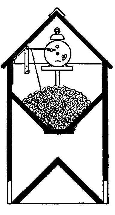
An automatic poultry feeder, which will discharge the necessary
amount of corn or other feed at any desired time, may be made by
using an alarm clock as shown in the sketch. A small wire trigger
rests on the winding key and supports the swinging bottom of the
food hopper by means of a piece of string which connects the two.
When the alarm goes off the trigger drops and allows the door to
open, thus discharging the contents of the hopper. After the
device has been in operation for some time the hens will run to
the feeder whenever the bell rings.
Contributed by Dr. H. A. Dobson, Washington, D. C.
Homemade Disk-Record Cabinet
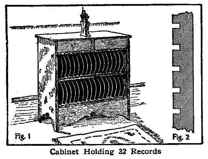
Cabinet Holding 32 Records
Select some boards that have a nice grain and about 1 in. thick
and 12-in. wide. Cut the end pieces each 36-in. long and trim
down the edges so as to make them 11-3/8 in. wide. The top board
is made 28-in. long and full 12-in. wide. The three shelves are
cut 25-in. long and the edges trimmed so they will be 11-3/8 in.
wide. The distance between the bottom of the top board and the
top of the first shelf should be 3 in. Two drawers are fitted in
this space, as shown in Fig. 1. A series of grooves are cut 1/4
in. wide, 1/4 in. deep and 3/4 in. apart on one side of the top
and bottom shelves, as shown in Fig. 2, and on both sides of the
middle shelf. The shelves should be spaced 9-5/8 in. for 10-in.
records and 5-5/8 in. for 6-in. records. A neat scroll design is
cut from a board 25 in. long to fill up and finish the space
below the bottom shelf.
Contributed by H. E. Mangold, Compton, Cal.
A Battery Rheostat
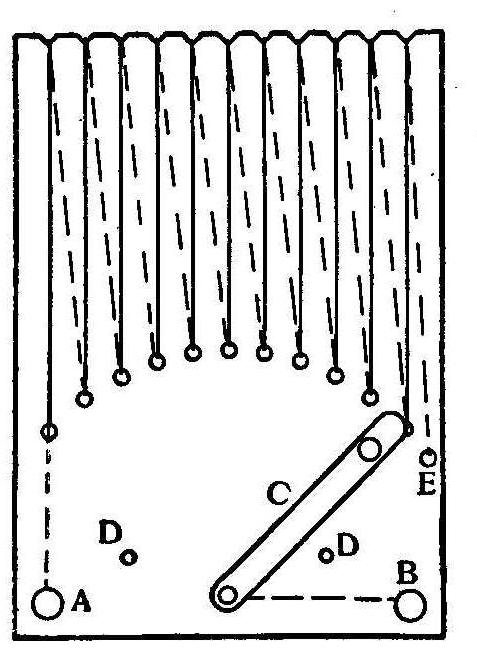
Battery Rheostat
In a board 7 in. long and 5 in. wide bore holes about 1/4 in.
apart, in a semicircle 2 in. from the bottom, and cut notches in
top end to correspond with the holes. From a piece of brass a
switch, C, is cut with a knob soldered on at the end. Nails for
stops are placed at DD. Two binding-posts are placed in board at
A and B. With about 9 ft. of fine iron wire attach one end to the
bottom of post A and run through first hole and over in first
notch to back of board and then through second hole and over
second notch and so on until E is reached, where the other end of
wire is fastened. Connect switch to post B.
Contributed by Edmund Kuhn, Jr., East Orange, N. J.
Automatic Time Switch
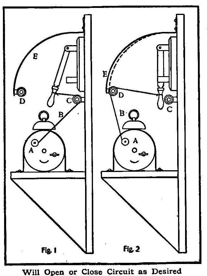
Will Open or Close Circuit as Desired
This device may be used to either open or close the circuit at
any desired time. An alarm clock is firmly fastened to a wooden
bracket and provided with a small wood or metal drum, A, to which
is fastened a cord, B. The other end of the cord is tied to the
switch handle so that when the alarm goes off the switch is
either opened or closed, depending on whether the cord is
passed over pulley C or pulley D.
When the cord is passed over pulley C, as shown in Fig. 1, the
circuit will be closed when the alarm goes off, but if it is
passed over D the circuit will be opened. Pulley D is fastened to
a piece of spring steel, E, which in operation is bent, as shown
by the dotted lines, thus causing the switch to snap open quickly
and prevent forming an arc.
Contributed by Douglas Royer, Roanoke, Va.
How to Make a Rotary Pump
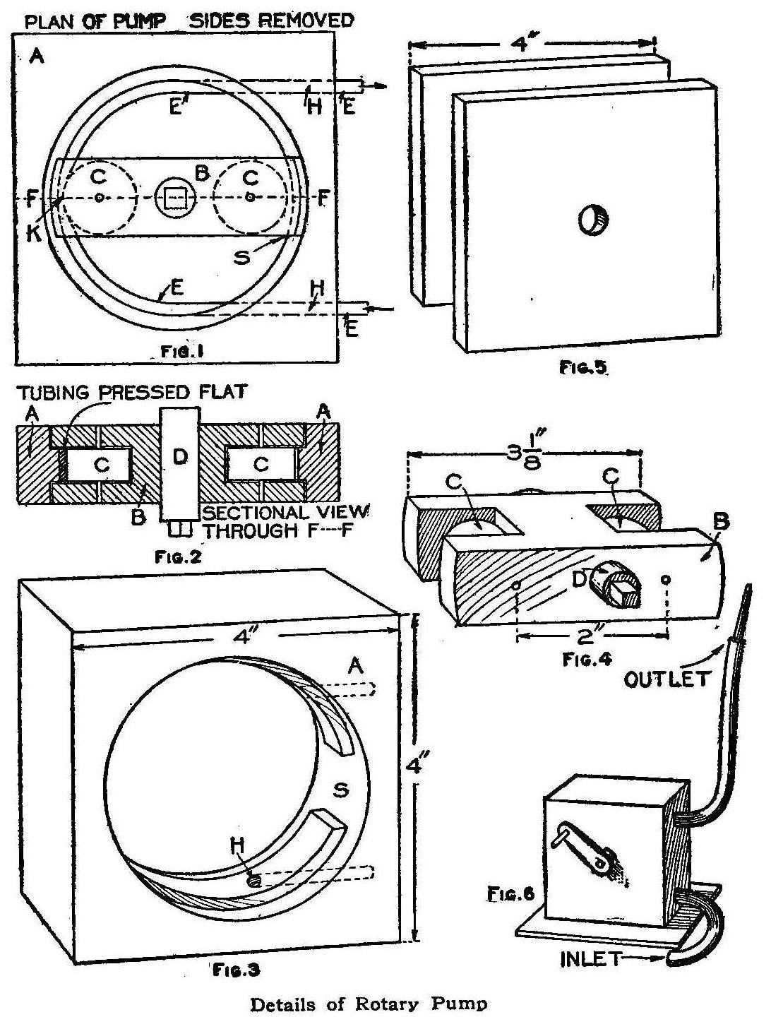
Details of Rotary Pump
A simple rotary pump is constructed on the principle of creating
a vacuum in a rubber tube and so causing water to rise to fill
the vacuum. Figs. 3, 4 and 5 show all the parts needed, excepting
the crank and tubing. The dimensions and description given are
for a minimum pump, but a larger one could be built in
proportion.
Through the center of a block of wood 4 in. square and 7/8 in.
thick (A, Figs. 1, 2 and 3) saw a circular opening 2-7/8 in. in
diameter. On each side of this block cut a larger circle 3-1/4
in. in diameter, having the same center as the first circle (Fig.
3). Cut the last circles only 1/4 in. deep, leaving the first
circle in the form of a ridge or track 3/8 in. wide, against
which the rubber tubing, E, is compressed by wheels. Bore two 1/4
in. holes (HH, Fig. 1) from the outside of the block to the edge
of the inner circle. Put the rubber tube, E, through one of these
holes, pass it around the track and out through the other hole.
Notice the break (S) in the track; this is necessary in order to
place in position the piece holding the wheels.
Fig. 4 shows the wheel-holder, B. Make it of hard wood 3-1/8 in.
long, 1 in. wide and a little less than 7/8 in. thick, so that it
will run freely between the sides (Fig. 5) when they are placed.
Cut two grooves, one in each end, 1 in. deep and 1/2 in. wide. In
these grooves place wheels, CC, to turn on pins of stout wire.
These wheels should be 3/4 in. in diameter. When placed in the
holder their centers must be exactly 2 in. apart, or so arranged
that the distance between the edge of the wheels and the track
(K, Fig. 1) is equal to the thickness of the tubing when pressed
flat. If the wheels fit too tightly, they will bind; it too
loose, they will let the air through. Bore a hole through the
middle of the wheel-holder and insert the crankpin, D, which
should be about 1/2 in. in diameter. The crankpin should fit
tightly; if necessary drive a brad through to keep it from
slipping.
In the sides (Fig. 5) bore a hole in the center of the crankpin
to run in loosely. Now put all these parts together, as shown in
the illustration. Do not fasten the sides too securely until you
have tried the device and are sure it will run smoothly. For the
crank a bent piece of stout wire or a nail will serve, though a
small iron wheel is better, as it gives steadiness to the motion.
In this case a handle must be attached to the rim of the wheel to
serve as a crank. The drive wheel from a broken-down eggbeater
will do nicely. For ease in handling the pump, a platform should
be added.
To use the pump, fill the tube with water and place the lower end
of the tube in a reservoir of water. Make a nozzle of the end of
a clay pipe stem for the other end of the tube. Then turn the
crank from left to right. The first wheel presses the air out of
the tube, creating a vacuum which is immediately filled with
water. Before the first wheel releases the tube at the top, the
other wheel has reached the bottom, this time pressing along the
water that was brought up by the first wheel. If the motion of
the wheels is regular, the pump will give a steady stream. Two
feet of 1/4-in. tubing, costing 10 cents, is all the expense
necessary.
Contributed by Dan H. Hubbard, Idana, Kan.
How to Make a Fire Screen
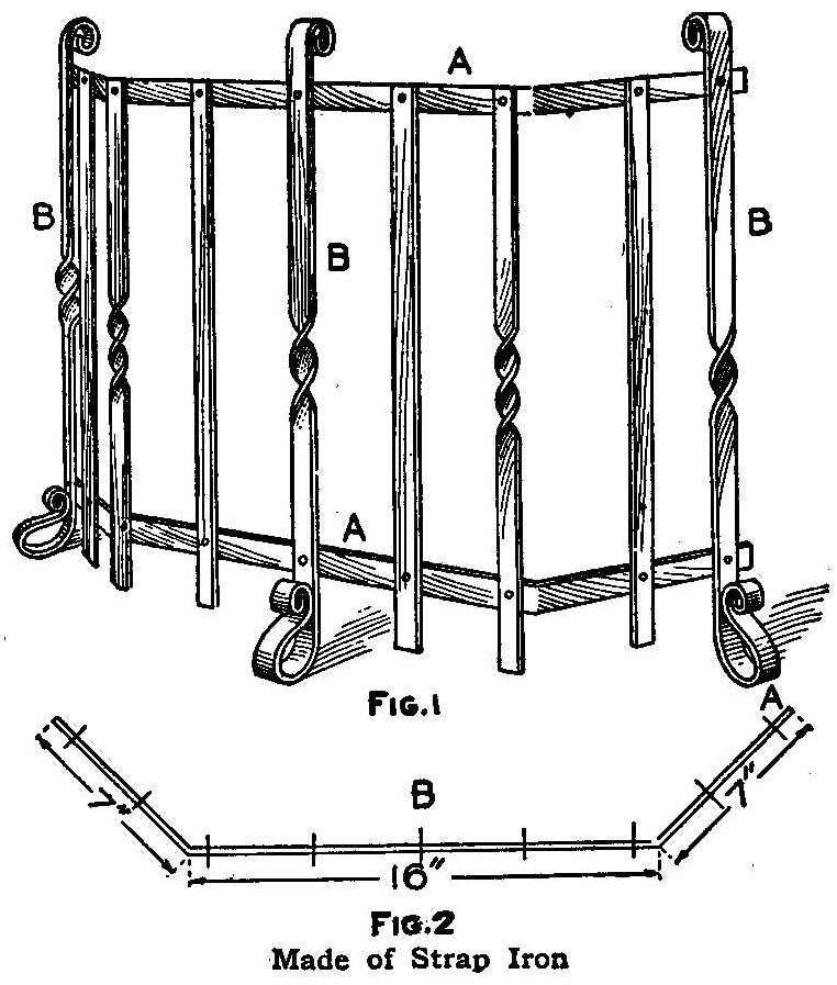
Fig. 1
Fig. 2 Made of Strap Iron
A screen which will not interfere with the radiation of the heat
from the fire, and will keep skirts and children safe can be made
at little expense out of some strap iron. The screen which is
shown in Fig. 1, stands 20 in. high from the base to the top
cross-piece and is made of 3/4 by 1/4-in. and 1/2 by 1/4-in.
iron. The top and bottom pieces marked AA, Fig. 1, are 3/4 by 1/4
in. and are 30 in. long, bent at an angle to fit the fireplace 7
in. from each end, as shown in Fig. 2. The three legs marked BBB,
Fig. 1, are of the same size iron and each leg will take 34 in.
of material. In shaping the feet of these three pieces give them
a slight tendency to lean toward the fire or inside of screen,
says a correspondent in the Blacksmith and Wheelwright. In the
two cross bars 1 in. from each end, A in Fig. 2, mark for hole
and 3 in. from that mark the next hole. Take the center of the
bar, B, 15 in. from each end, and mark for a hole, and 3-1/2 in.
on each side mark again and 3-1/2 in. beyond each of these two,
mark again.
Mark the legs 2-3/4 in. from the bottom and 2 in. from the top
and after making rivet-holes rivet them to the cross bars, AA,
Fig. 1.
Cut six pieces, 17-1/2 in. long and punch holes to fit and rivet
onto the remaining holes in cross bars, AA, Fig. 1. Clean it up
and give it a coat of black Japan or dead black.
Trap for Small Animals
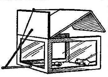
This is a box trap with glass sides and back, the panes of glass
being held in place by brads placed on both sides. The animal
does not fear to enter the box, because he can see through it:
when he enters, however, and touches the bait the lid is released
and, dropping, shuts him in. This is one of the easiest traps to
build and is usually successful.
Homemade Grenet Battery
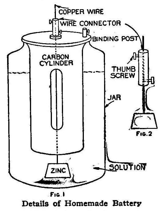
Fig.1 Details of Homemade Battery
Procure an ordinary carbon-zinc, sal-ammoniac battery and remove
the zinc rod. If the battery has been used before, it is better
to soak the carbon cylinder for a few hours to remove any
remaining crystals of sal-ammoniac from its pores.
The truncated, conical zinc required is known as a fuller’s zinc
and can be bought at any electrical supply dealer’s, or, it may
be cast in a sand mold from scrap zinc or the worn-out zinc rods
from sal-ammoniac batteries. It should be cast on the end of a
piece of No. 14 copper wire. Amalgamation is not necessary for
the zinc one buys, but if one casts his own zinc, it is necessary
to amalgamate it or coat it with mercury. This may be done as
follows:
Dip a piece of rag in a diluted solution of sulphuric acid (water
16 parts, acid 1 part); rub the zinc well, at the same time
allowing a few drops of mercury
to fall on a spot attacked by the
acid. The mercury will adhere,
and if the rubbing is continued so
as to spread the mercury,
it will cover the entire surface of the
zinc, giving it a bright, silvery appearance.
Next procure what is known as a wire connector. This is a piece
of copper tube about 1-1/2 in. long having two thumb screws, one
on each end on opposite sides (Fig. 2). The upper screw is to
connect the battery wire, the lower one to raise and lower the
zinc. The battery is now complete, and the solution (Fig. 1) must
be prepared. Proceed as follows:
In 32 oz. of water dissolve 4 oz. potassium bichromate. When the
bichromate has all dissolved, add slowly, stirring constantly, 4
oz. sulphuric acid.
Do not add the acid too quickly or the heat
generated may break the vessel containing the solution. Then pour
the solution into the battery jar, until it is within 3 in. of
the top. Thread the wire holding the zinc through the porcelain
insulator of the carbon cylinder and also through the wire
connector. Pull the zinc up as far as it will go and tighten the
lower thumb screw so that it holds the wire secure. Place the
carbon in the jar. If the solution touches the zinc, some of it
should be poured out. To determine whether or not the zinc is
touched by the solution, take out the carbon and lower the zinc.
If it is wet, there is too much liquid in the jar. The battery is
now ready for use.
To cause a flow of electricity, lower the zinc until it almost
touches the bottom of the jar and connect an electric bell or
other electrical apparatus by means of wires to the two binding
posts.
This battery when first set up gives a current of about two
volts. It is useful for running induction coils, or small
electric motors. When through using the battery, raise the zinc
and tighten the lower thumb screw. This prevents the zinc wasting
away when no current is being used.
Contributed by H. C. Meyer, Philadelphia.
Door-Opener for Furnace
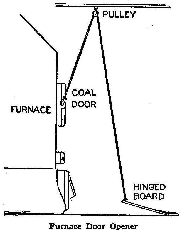
Furnace Door Opener
The accompanying diagram shows an arrangement to open the coal
door of a furnace. When approaching the furnace with a shovelful
of coal it is usually necessary to rest the shovel on the top of
the ash door, while the coal door is being opened. With my device
it is only necessary to press the foot pedal, which opens the
door. After putting in the coal, pressing the pedal closes the
door. The pulley in the ceiling must be placed a little in front
of the door, in order to throw the door open after lifting it
from the catch. A large gate hinge is used to hold the pedal to
the floor.
Contributed by Edward Whitney, Madison, Wis.
How to Make an Efficient Wireless Telegraph
By George W. Richardson
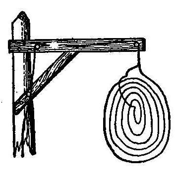

A simple but very efficient wireless telegraph may be constructed
at slight cost from the following description:
The sending apparatus consists of nothing but an induction coil
with a telegraph key inserted in the primary circuit, i. e., the
battery circuit. This apparatus may be purchased from any
electrical-supply house. The price of the coil depends upon its
size, and upon the size depends the distance signals can be
transmitted. If, however, one wishes to construct his own coil he
can make and use, with slight changes, the jump-spark coil
described elsewhere in this book. This coil, being a 1-in. coil,
will transmit nicely up to a distance of one mile; while a 12-in.
coil made on the same plan will transmit 20 miles or even more
under favorable conditions.
Change the coil described, as follows: Insert an ordinary
telegraph key in the battery circuit, and attach two small pieces
of wire with a brass ball on each, by inserting them in the
binding-posts of the coil as shown at B B”. Of these two terminal
wires one is grounded to earth, while the other wire is sent
aloft and is called the aerial line. This constitutes all there
is to the sending apparatus. Now for the receiving apparatus. In
the earlier receiving instruments a coherer was used, consisting
of a glass tube about 1/8-in. diameter, in which were two silver
pistons separated by nickel and silver filings, in a partial
vacuum. This receiver was difficult of adjustment and slow in
transmission. An instrument much less complicated and inexpensive
and which will work well can be made thus:
Take a 5-cp. incandescent lamp and break off the tip at the
dotted line, as shown in Fig. 5. This can be done by giving the
glass tip or point a quick blow with a file or other thin edged
piece of metal. Then with a blow-torch heat the broken edges
until red hot and turn the edges in as seen in Fig. 6. Remove the
carbon filament in the lamp and bend the two small platinum wires
so they will point at each other as in Fig. 6, W W. Screw the
lamp into an ordinary wall socket which will serve as a base as
in Fig. 7. Make a solution of 1 part
sulphuric acid to 4 parts of
water, and fill the lamp about two-thirds full (Fig. 7). This
will make an excellent receiver. It will be necessary to adjust
the platinum points, W W, to suit the distance the message is to
be worked. For a mile or less the points should be about 1/16 in.
apart, and closer for longer distances.
The tuning coil is simply a variable choking coil, made of No. 14
insulated copper wire wound on an iron core, as shown in Fig. 7.
After winding, carefully scrape the insulation from one side of
the coil, in a straight line from top to bottom, the full length
of the coil, uncovering just enough to allow a good contact for
the sliding piece. The tuning is done by sliding the contact
piece, which is made of light copper wire, along the convolutions
of the tuning coil until you can hear the signals. The signals
are heard in a telephone receiver, which is shown connected in
shunt across the binding posts of the lamp holder with one or two
cells of dry battery in circuit, Fig.7.
The aerial line, No.6 stranded, is run from binding-post B
through the choking or tuning coil, and for best results should
extend up 50 ft. in the air. To work a 20-mile distance the line
should be 100 or 150 ft. above the ground. A good way is to erect
a wooden pole on a house or barn and carry the aerial wire to the
top and out to the end of a gaff or arm.
To the end of the aerial wire fasten a bunch of endless loops
made of about No. 14 magnet wire (bare or insulated), attaching
both ends to the leading or aerial wire. The aerial wire should
not come nearer than 1 ft. at any point to any metal which is
grounded.
Run a wire from the other binding post, A, to the ground and be
sure to make a good ground connection.
For simple experimental work on distances of 100 ft. only, an
ordinary automobile spark coil can be used in place of the more
elaborate coil, Figs. 1 to 4.
The above-mentioned instruments have no patents on them, and
anyone is at liberty to build and use them. The writer does not
claim to be the originator, but simply illustrates the above to
show that, after all, wireless is very simple when it is once
understood. The fundamental principles are that induction travels
at right angles, 90°, to the direction of the current. For an
illustration, if a person standing on a bridge should drop a
pebble into the water below, after contact he would note circles
radiating out over the surface of the water. These circles, being
at right angles, 90°, to the direction of the force that caused
the circles, are analogous to the flow of induction, and hence
the aerial line, being vertical, transmits signals horizontally
over the earth’s surface.
Beeswax for Wood Filler
When filling nail holes in yellow pine use beeswax instead of
putty, as it matches the color well.
How to Make a Lathe
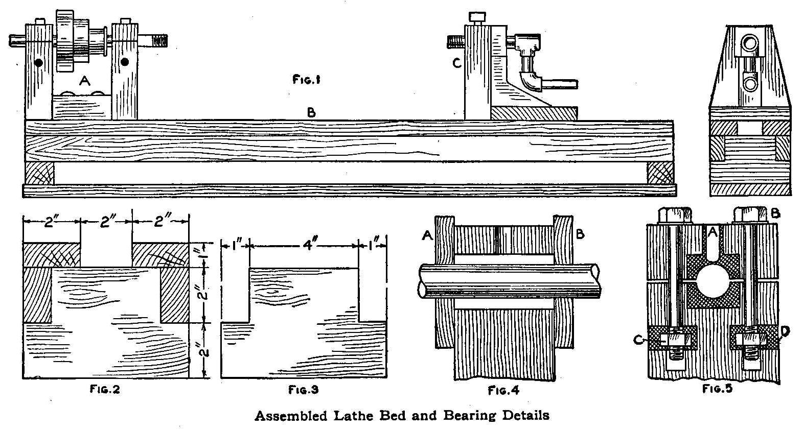
Assembled Lathe Bed and Bearing Details
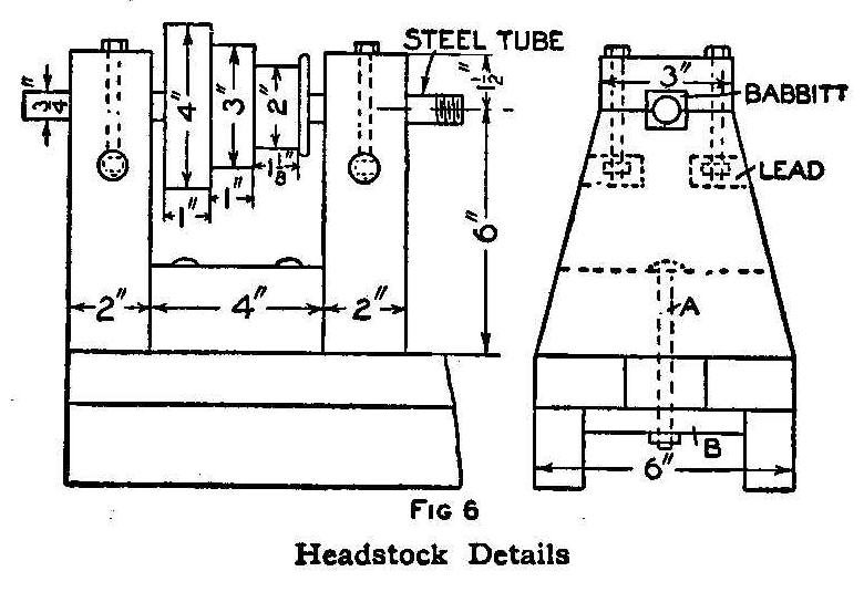
FIG. 6 Headstock Details
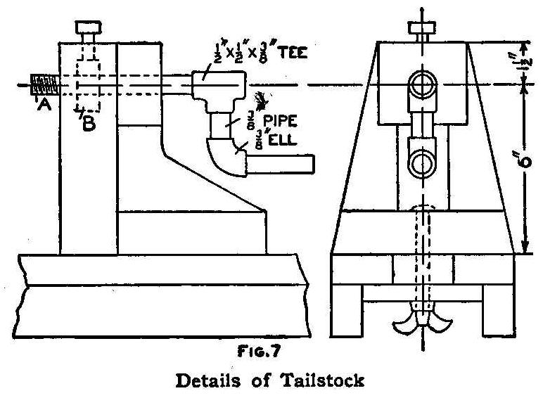
FIG.7 Details of Tailstock
A small speed-lathe, suitable for turning wood or small metal
articles, may be easily made at very little expense. A lathe of
this kind is shown in the cut (Fig. 1), where A is the headstock,
B the bed and C the tailstock. I run my lathe by power, using an
electric motor and countershaft, but it could be run by foot
power if desired. A large cone pulley would then be required, but
this may be made in the same manner as the small one, which will
be described later.
The bed of the machine is made of wood as shown in Figs. 2 and 3,
hardwood being preferable for this purpose. Fig. 2 shows an end
view of the assembled bed, and Fig. 3 shows how the ends are cut
out to receive the side pieces.
The headstock, Fig. 6, is fastened to the bed by means of
carriage bolts, A, which pass through a piece of wood, B, on the
under side of the bed. The shaft is made of 3/4-in. steel tubing
about 1/8 in. thick, and runs in babbitt bearings, one of which
is shown in Fig. 5.
To make these bearings, cut a square hole in the wood as shown,
making half of the square in each half of the bearing. Separate
the two halves of the bearing slightly by placing a piece of
cardboard on each side, just touching the shaft. The edges which
touch the shaft should be notched like the teeth of a saw, so as
to allow the babbitt to run into the lower half of the bearing.
The notches for this purpose may be about 1/8 in. pitch and 1/8
in. deep. Place pieces of wood against the ends of the bearing as
shown at A and B, Fig. 4, and drill a hole in the top of the
bearing as shown in Fig. 4.
The bearing is then ready to be poured. Heat the babbitt well,
but not hot enough to burn it, and it is well to have the shaft
hot, too, so that the babbitt will not be chilled when it strikes
the shaft. If the shaft is thoroughly chalked or smoked the
babbitt will not stick to it. After pouring, remove the shaft and
split the bearing with a round, tapered wooden pin. If the
bearing has been properly made, it will split along the line of
the notched cardboard where the section of the metal is smallest.
Then drill a hole in the top as shown at A, Fig. 5, drilling just
deep enough to have the point of the drill appear at the lower
side. This cavity acts as an oil cup and prevents the bearing
from running dry.
The bolts B (Fig. 5) are passed through holes in the wood and
screwed into nuts C, which are let into holes D, the holes
afterward being filled with melted lead.
This type of bearing will be found very satisfactory and may be
used to advantage on other machines. After the bearings are
completed the cone pulley can be placed on the shaft. To make
this pulley cut three circular pieces of wood to the dimensions
given in Fig. 6 and fasten these together with nails and glue. If
not perfectly true, they may be turned up after assembling, by
rigging up a temporary toolrest in front of the headstock.
The tail stock (Fig. 7) is fastened to the bed in the same manner
as the headstock, except that thumb nuts are used on the carriage
bolts, thus allowing the tail stock to be shifted when necessary.
The mechanism of the center holder is obtained by using a l/2-in.
pipe, A, and a 1/2-in. lock nut, B, embedded in the wood.
I found that a wooden tool-rest was not satisfactory, so I had to
buy one, but they are inexpensive and much handier than homemade
tool rest.
Contributed by Donald Reeves, Oak Park, Ill.
To Use Old Battery Zincs
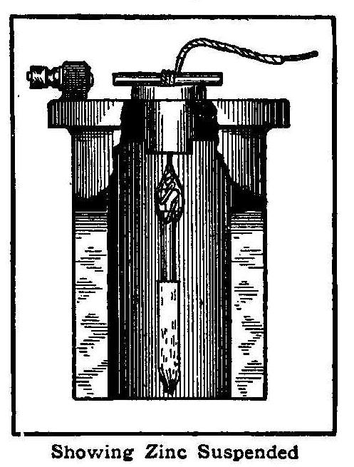
Showing Zinc Suspended
When the lower half of a battery zinc becomes eaten away the
remaining part can be used again by suspending it from a wire as
shown in the cut. Be sure and have a good connection at the zinc
binding post and cover that with melted paraffin. This prevents
corrosion, which would otherwise occur from the action of the sal
ammoniac or other chemical. The wire may be held at the top by
twisting it around a piece of wood or by driving a peg through
the hole in the porcelain insulator.
Contributed by Louis Lauderbach, Newark, N.J.
Callers’ Approach Alarm
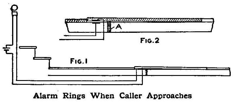
Alarm Rings When Caller Approaches
This alarm rings so that callers approaching the door may be seen
before they ring the bell and one can exercise his pleasure about
admitting them.
If one has a wooden walk, the alarm is easy to fix up. Take up
about 5 ft. of the walk and nail it together so as to make a
trapdoor that will work easily. Place a small spring under one
end to hold it up about 1/4 in. (A, Fig. 2). Nail a strip of tin
along the under side of the trap near the spring and fasten
another strip on the baseboard, so that they will not touch, save
when a weight is on the trap. Connect up an electric bell,
putting the batteries and bell anywhere desired, and using
rubber-covered wire outside the house, and the alarm is complete.
When a person approaching the house steps on the trap, the bell
will ring and those in the house can see who it is before the
door bell rings.
Contributed by R. S. Jackson, Minneapolis, Minn.
Easy Method of Electroplating
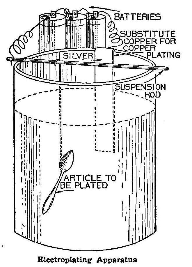
Electroplating Apparatus
Before proceeding to electroplate with copper, silver or other
metal, clean the articles thoroughly, as the least spot of grease
or dirt will prevent the deposit from adhering. Then polish the
articles and rub them over with a cloth and fine pumice powder,
to roughen the surface slightly. Finally, to remove all traces of
grease, dip the articles to be plated in a boiling potash
solution made by dissolving 4 oz. American ash in 1-1/2 pt. of
water. Do not touch the work with the hands again. To avoid
touching it, hang the articles on the wires, by which they are to
be suspended in the plating bath, before dipping them in the
potash solution; then hold them by the wires under running water
for ten minutes to completely remove every trace of the potash.
For plating with copper prepare the following solution: 4 oz.
copper sulphate dissolved in 12 oz. water; add strong ammonia
solution until no more green crystals are precipitated. Then add
more ammonia and stir until the green crystals are redissolved
giving an intense blue solution. Add slowly a strong solution of
potassium cyanide
until the blue color disappears, leaving a
clear solution; add potassium cyanide
again, about one-fourth as
much in bulk as used in the decolorizing process. Then make the
solution up to 2 qt. with water. With an electric pressure of 3.5
to 4 volts, this will give an even deposit of copper on the
article being plated.
A solution for silver plating may be prepared as follows:
Dissolve 3/4 oz. of commercial silver nitrate in 8 oz. of water,
and slowly add a strong solution of
potassium cyanide until no
more white precipitate is thrown down. Then pour the liquid off
and wash the precipitate carefully. This is best done by filling
the bottle with water, shaking, allowing precipitate to settle
and then pouring off the water. Repeat six times. Having finished
washing the precipitate, slowly add to it a solution of
potassium cyanide
until all the precipitate is dissolved. Then add an
excess of potassium cyanide—about
as much as was used in dissolving the precipitate—and make the
solution up to 1 qt. with water. This solution, with an electric
pressure of 2 to 4 volts, will give a good white coat of silver
in twenty minutes to half-an-hour; use 2 volts for large
articles, and 4 volts for very small ones. If more solution is
required, it is only necessary to double all given quantities.
Before silver plating, such metals as iron,
lead, pewter, zinc,
must be coated with copper in the alkaline copper bath described,
and then treated as copper. On brass, copper, German silver,
nickel and such metals, silver can be plated direct. The deposit
of silver will be dull and must be polished. The best method is
to use a revolving scratch brush; if one does not possess a
buffing machine, a hand scratch brush is good. Take quick, light
strokes. Polish the articles finally with ordinary plate powder.
The sketch shows how to suspend the articles in the plating-bath.
If accumulators are used, which is advised, be sure to connect
the positive (or red) terminal to the piece of silver hanging in
the bath, and the negative (or black) terminal to the article to
be plated. Where Bunsen cells are used, the carbon terminal takes
the place of the positive terminal of the accumulator.
Model Engineer.
An Ingenious Electric Lock for a Sliding Door
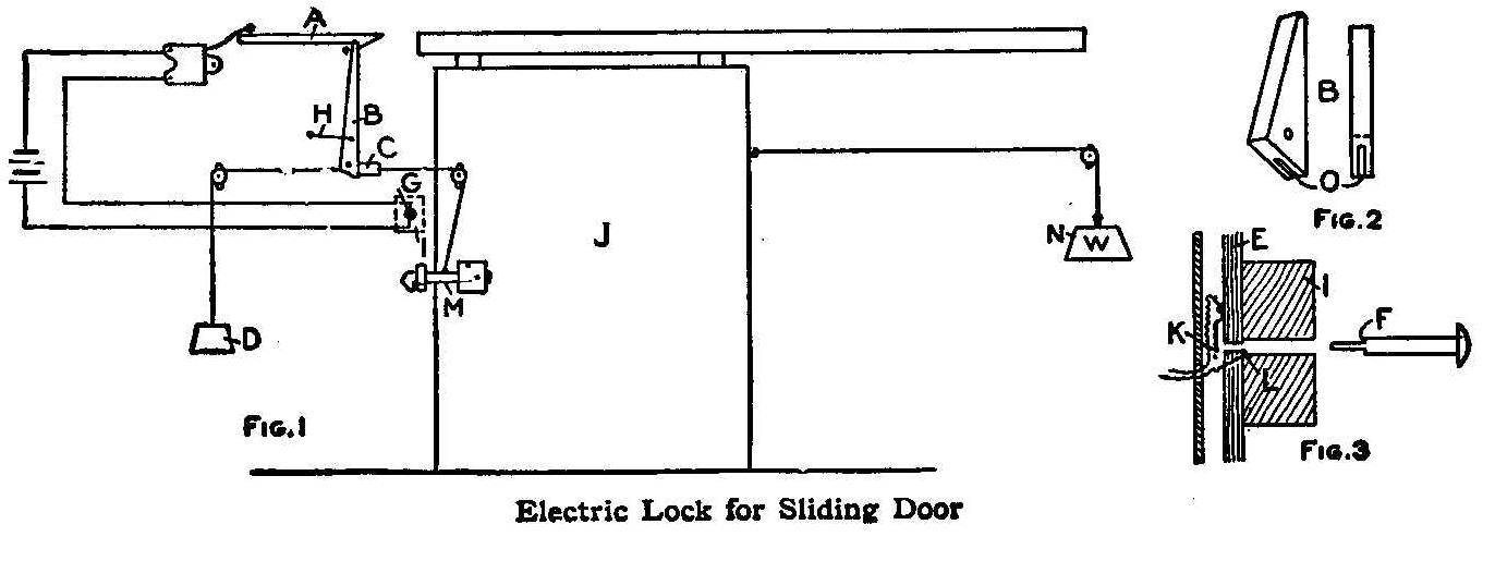
Electric Lock for Sliding Door
The apparatus shown in Fig. 1 not only unlocks, but opens the
door, also, by simply pressing the key in the keyhole.
In rigging it to a sliding door, the materials required are:
Three flat pulleys, an old electric bell or buzzer, about 25 ft.
of clothesline rope and some No. 18 wire. The wooden catch, A
(Fig. 1), must be about 1 in. thick and 8 in. long; B should be
of the same wood, 10 in. long, with the pivot 2 in. from the
lower end. The wooden block C, which is held by catch B, Can be
made of a 2-in. piece of broomstick. Drill a hole through the
center of this block for the rope to pass through, and fasten it
to the rope with a little tire tape.
When all this is set up, as shown in Fig. 1, make a key and
keyhole. A 1/4 in. bolt or a large nail sharpened to a point, as
at F, Fig. 3, will serve for the key. To provide the keyhole, saw
a piece of wood, I, 1 in. thick by 3 in. square, and bore a hole
to fit the key in the center. Make a somewhat larger block (E,
Fig. 3) of thin wood with a 1/8-in. hole in its center. On one
side of this block tack a piece of tin (K, Fig. 3) directly over
the hole. Screw the two blocks together, being careful to bring
the holes opposite each other. Then, when the point of the key
touches the tin, and the larger part (F, Fig. 3) strikes the bent
wire L, a circuit is completed; the buzzer knocks catch A (Fig.
1), which rises at the opposite end and allows catch B to fly
forward and release the piece of broomstick C. The weight D then
falls and jerks up the hook-lock M, which unlocks the door, and
the heavier weight N immediately opens it.
Thus, with a switch as
in Fig. 3, the door can only be opened by the person who has the
key, for the circuit cannot be closed with an ordinary nail or
wire. B, Fig. 2, shows catch B, Fig. 1, enlarged; O, Fig. 2, is
the cut through which the rope runs; H, Fig. 1, is an elastic
that snaps the catch back into place, and at G the wires run
outside to the keyhole.
This arrangement is very convenient when one is carrying
something in one hand and can only use the other. Closing the
door winds up the apparatus again.
Contributed by E. H. Klipstein, 116 Prospect St., East Orange, New Jersey.
Parlor Magic for Winter Evenings
By C. H. CLAUDY
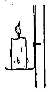
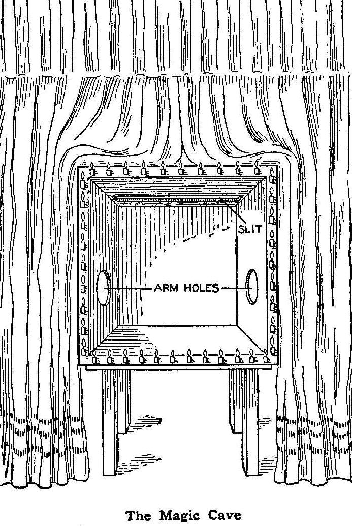
The Magic Cave
You are seated in a parlor at night, with the lights turned low.
In front of you, between the parlor and the room back of it, is
an upright square of brightly burning lights, surrounding a
perfectly black space. The magician stands in front of this, in
his shirt sleeves, and after a few words of introduction proceeds
to show the wonders of his magic cave. Showing you plainly that
both hands are empty, he points with one finger to the box, where
immediately appears a small white china bowl. Holding his empty
hand over this bowl, some oranges and apples drop from his empty
hand into the bowl. He removes the bowl from the black box, or
cave, and hands its contents round to the audience. Receiving the
bowl again, he tosses it into the cave, but it never reaches the
floor—it disappears in midair.
The illusions he shows you are too many to retail at length.
Objects appear and disappear. Heavy metal objects, such as forks,
spoons and jackknives, which have been shown to the audience and
which can have no strings attached to them, fly about in the box
at the will of the operator. One thing changes to another and
back again, and black art reigns supreme.
Now all this “magic” is very simple and requires no more skill to
prepare or execute than any clever boy or girl of fourteen may
possess. It is based on the performance of the famous Hermann,
and relies on a principle of optics for its success. To prepare
such a magic cave, the requisites are a large soap box, a few
simple tools, some black paint, some black cloth, and plenty of
candles.
The box must be altered first. One end is removed, and a slit,
one-third of the length from the remaining end, cut in one side.
This slit should be as long as the width of the box and about
five inches wide. On either side of the box, half way from open
end to closed end, should be cut a hole, just large enough to
comfortably admit a hand and arm.
Next, the box should be painted black both inside and out, and
finally lined inside with black cloth. This lining must be done
neatly-no folds must show and no heads of tacks. The interior
must be a dead black. The box is painted black first so that the
cloth used need not be very heavy; but if the cloth be
sufficiently thick, no painting inside is required. The whole
inside is to be cloth-lined, floor, top, sides and end.
Next, the illumination in front must be arranged. If you can have
a plumber make you a square frame of gas-piping, with tiny holes
all along it for the gas to escape and be lit, and connect this
by means of a rubber tube to the gas in the house, so much the
better; but a plentiful supply of short candles will do just as
well, although a little more trouble. The candles must be close
together and arranged on little brackets around the whole front
of the “cave” (see small cut), and should have little pieces of
bright tin behind them, to throw the light toward the audience.
The whole function of these candles is to dazzle the eyes of the
spectators, heighten the illusion, and prevent them seeing very
far into the black box.
Finally, you must have an assistant, who must be provided with
either black gloves or black bags to go over his hands and arms,
and several black drop curtains, attached to sticks greater in
length than the width of the box, which are let down through the
slit in the top.
The audience room should have only low lights; the room where the
cave is should be dark, and if you can drape portieres between
two rooms around the box (which, of course, is on a table) so
much the better.
The whole secret of the trick lies in the fact that if light be
turned away from anything black, into the eyes of him who looks,
the much fainter light reflected from the black surface will not
affect the observer’s eye. Consequently, if, when the exhibitor
puts his hand in the cave, his confederate behind inserts his
hand, covered with a black glove and holding a small bag of black
cloth, in which are oranges and apples, and pours them from the
bag into a dish, the audience sees the oranges and apples appear,
but does not see the black arm and bag against the black
background.
The dish appears by having been placed in position behind a black
curtain, which is snatched swiftly away at the proper moment by
the assistant. Any article thrown into the cave and caught by the
black hand and concealed by a black cloth seems to disappear.
Any object not too large can be made to “levitate” by the same
means. A picture of anyone present may be made to change into a
grinning skeleton by suddenly screening it with a dropped
curtain, while another curtain is swiftly removed from over a
pasteboard skeleton, which can be made to dance either by
strings, or by the black veiled hand holding on to it from
behind, and the skeleton can change to a white cat.
But illusions suggest themselves. There is no end to the effects
which can be had from this simple apparatus, and if the operators
are sufficiently well drilled the result is truly remarkable to
the uninitiated. The illusion, as presented by Hermann, was
identical with this, only he, of course, had a big stage, and
people clothed in black to creep about and do his bidding, while
here the power behind the throne is but a black-veiled hand and
arm. It can be made even more complicated by having two
assistants, one on each side of the box, and this is the reason
why it was advised that two holes be cut. This enables an
absolutely instantaneous change as one uncovers the object at the
moment the second assistant covers and removes the other.
It is important that the assistants remain invisible throughout,
and if portieres are impossible, a screen must be used. But any
boy ingenious enough to follow these simple instructions will not
need to be told that the whole success of the exhibition depends
upon the absolute failure of the audience to understand that
there is more than one concerned in bringing about the curious
effects which are seen. The exhibitor should be a boy who can
talk; a good “patter”—as the magicians call it—is often of
more value than a whole host of mechanical effects and helpers.
It is essential that the exhibitor and his confederate be well
drilled, so that the latter can produce the proper effects at
the proper cue from the former. Finally, never give an exhibition
with the “cave” until you have watched the illusions from the
front yourself; so that you can determine whether everything
connected with the draping is right, or whether some stray bit of
light reveals what you wish to conceal.
Reversing-Switch for Electrical Experiments
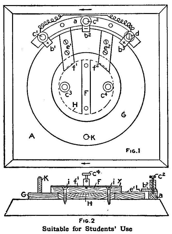
Fig. 2 Suitable for Students’ Use
A homemade reversing-switch, suitable for use by students of
electrical and engineering courses in performing experiments, is
shown in the diagram.
Referring to Fig. 1, A represents a pine board 4 in. by 4 in. and
a is a circular piece of wood about 1/4 in. square, with three
brass strips, b1, b2, b3, held down on it by two terminals, or
binding posts, c1, c2, and a common screw, d. Post c1 is
connected to d by means of an insulated wire, making them carry
the same kind of current (+ in the sketch).
About the center piece H moves a disk, held down by another disk
F (Fig. 2), which is fastened through the center piece to the
wooden base, A, by means of two wood screws. On the disk G are
two brass strips, e1 and e2, so arranged that, when handle K is
turned to one side, their one end just slips under the strips b1,
b2, or b2, b3, respectively, making contact with them, as shown
in Fig. 2, at L, while their other ends slide in two
half-circular brass plates f1, f2, held down on disk F by two
other terminals, c3, c4, making contact with them as shown at y,
Fig. 2.
The action of the switch is shown in Fig. 1. Connect terminal c1
to the carbon of a battery, and c2 to the zinc. Then, if you turn
handle K to the right, so that the strips e1 and e2 touch b1 and
b2, respectively, terminal c3 will show +, and c1 – electricity;
vice versa, if you turn the handle to the left so that e1 and e2
touch b2 and b3, respectively, terminal c3 will show – , and c4 +
electricity. The switch is easy to make and of very neat
appearance.
How to Receive Wireless Telegraph Messages with a Telephone
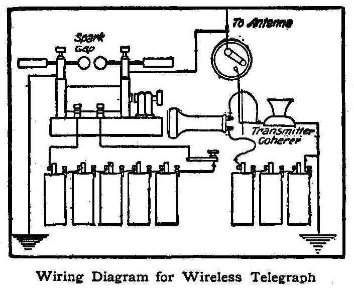
Wiring Diagram for Wireless Telegraph
Any telephone having carbon in the transmitter (all ordinary
telephones have carbon transmitters) can be used to receive
wireless messages by simply making a few changes in the
connections and providing a suitable antenna. Connect the
transmitter and receiver in series with three dry cells and run
one wire from the transmitter to the antenna. Connect the other
transmitter wire to a water or gas pipe in order to ground it,
and then hold the receiver to your ear. Any wireless telegraph
message within a radius of one mile will cause the transmitter to
act as a coherer, thus making the message audible in the
receiver.
By using an ordinary telephone transmitter and receiver and a
1/2-in. jump spark coil, a complete wireless telegraph station
may be made, which will send or receive messages for a radius of
one mile. The accompanying wiring diagram shows how to make the
connections. By putting in an extra switch three of the sending
batteries may be switched in when receiving, thus obviating the
necessity of an extra set of batteries.
Contributed by A. E. Joerin.
Connecting Up Batteries to Give Any Voltage
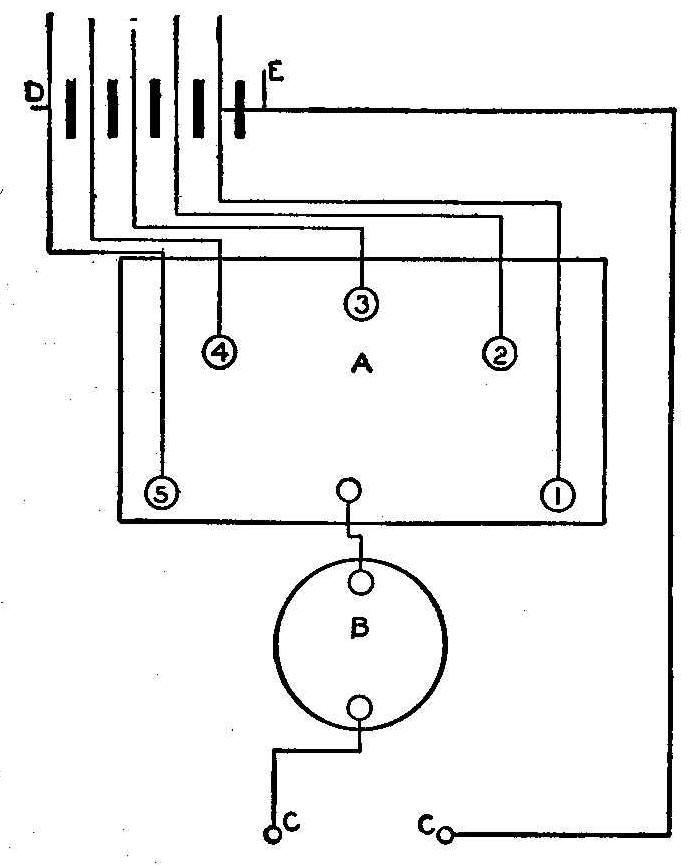
Referring to the illustration: A is a five-point switch (may be
homemade); B is a one-point switch, and C and C1 are binding
posts. When switch B is closed and A is on No. 1, you have the
current of one battery; when A is on No. 2 you receive the
current from two batteries; when on No. 3, from three batteries;
when on No. 4, from four batteries, and when on No. 5, from five
batteries. More batteries may be connected to each point of
switch B.
I have been using the same method for my water rheostat
(homemade). I have the jars of water where the batteries are and
the current coming in at a and b.
Contributed by Eugene F. Tuttle, Jr., Newark, Ohio.
A Simple Accelerometer
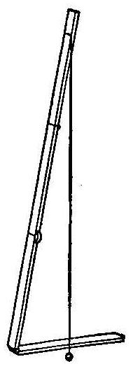
A simple accelerometer for indicating the increase in speed of a
train was described by Mr. A. P. Trotter in a paper read before
the Junior Institution of Engineers of Great Britain. The device
consists of an ordinary 2-ft. rule, A, with a piece of thread
tied to the 22-in. mark, as shown in the sketch, and supporting
the small weight, B, which may be a button or other small object.
The device thus arranged, and placed on the windowsill of the
car, will indicate the acceleration and retardation as follows:
Every 1/2 in. traveled by the thread, over the bent portion of
the rule, indicates an increase of or decrease of velocity to the
extent of 1 ft. per second for each second. Thus, it the thread
moved 2-1/4 in. in a direction opposite to the movement of the
train, then the train would be increasing its speed at the rate
of 4-1/2 ft. per second.
If the thread is tied at the 17-in. mark, then each half inch
will represent the mile per hour increase for each second. Thus
if the thread moves 1 in., it shows that the train is gaining 2
miles an hour each second.
An Egg-Shell Funnel
Bottles having small necks are hard to fill without spilling the
liquid. A funnel cannot be used in a small opening, and pouring
with a graduate glass requires a steady hand. When you do not
have a graduate at hand, a half egg-shell with a small hole
pricked in the end will serve better than a funnel. Place the
shell in an oven to brown the surface slightly and it will be
less brittle and last much longer.
Contributed by Maurice Baudier, New Orleans, La.
Handy Electric Alarm
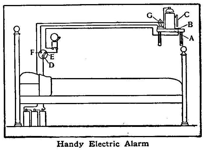
Handy Electric Alarm
An electric alarm which one may turn off from the bed without
arising combined with a light which may be turned on and off from
a lying position, so one can see the time, is the device of H. E.
Redmond, of Burlington, Wis.
The alarm clock rests on a shelf, A, which has a piece of metal,
B, fastened in such a position that the metal rod C, soldered to
the alarm winder, will complete the circuit and ring the bell.
The two-point switch D is closed normally at E, but may be
closed at F any time desired, thus turning on the small
incandescent light G, which illuminates the face of the clock.
When the alarm goes off, the bell will continue to ring until the
switch is opened.
To Keep Dogs and Cats Away from the Garbage-Can
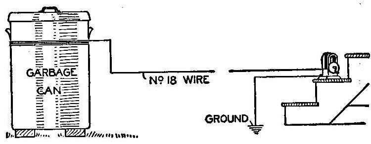
Last summer I was annoyed a great deal by dogs upsetting our
garbage can on the lawn, but finally executed a plan that rid the
yard of them in one afternoon.
I first secured a magneto out of an old telephone, then drove a
spike in a damp place under the porch, attached a wire to the
spike and ran the wire to one of the poles of the magneto. Then I
set the garbage-can on some blocks of wood, being careful not to
have it touch the ground at any point. I next ran a wire from the
other pole of the magneto to the can, wrapping the wire around
the can several times. Then I sat down on the porch to wait.
It was not long before a big greyhound came along, putting his
forepaws on the top of the can to upset it. At the same instant I
gave the magneto a quick turn, which sent the dog away a very
surprised animal. This was repeated several times during the
afternoon with other dogs, and with the same result.
Contributed by Gordon T. Lane, Crafton, Pa.
How to Cross a Stream on a Log
When crossing a water course on a fence rail or small log, do not
face up or down the stream and walk sideways, for a wetting is
the inevitable result. Instead, fix the eye on the opposite shore
and walk steadily forward. Then if a mishap comes, you will fall
with one leg and arm encircling the bridge.
C. C. S.
Relay Made from Electric Bell
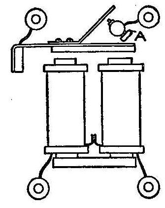
It is not necessary to remove the adjusting-screw when changing
an electric bell into a relay. Simply twist it around as at A and
bend the circuit-breaking contact back as shown. It may be
necessary to remove the head of the screw, A, to prevent
short-circuiting with the armature.
Contributed by A. L. Macey, New York City.
Foundry Work at Home
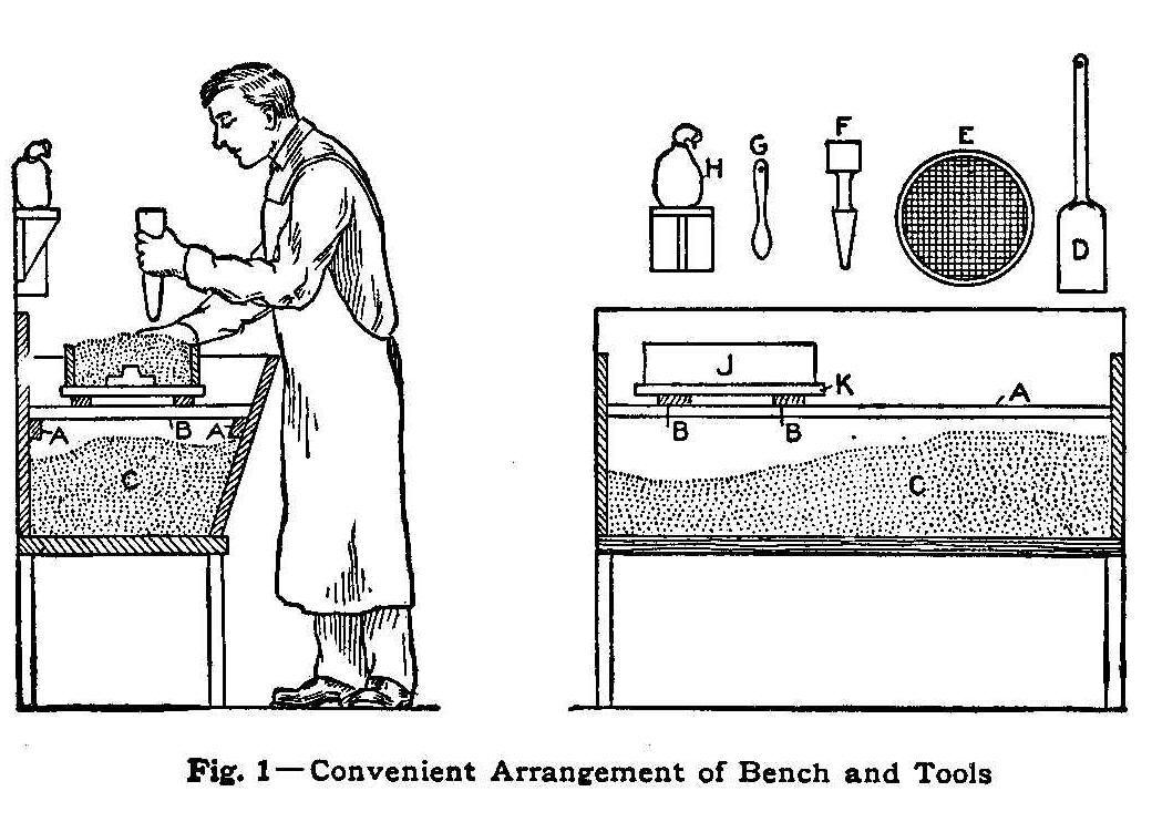
Fig. 1—Convenient Arrangement of Bench and Tools
The Equipment
Many amateur mechanics who require small metal castings in their
work would like to make their own castings. This can easily be
done at home without going to any great expense, and the variety
and usefulness of the articles produced will make the equipment a
good investment.
With the easily made devices about to be described, the young
mechanic can make his own telegraph keys and sounders, battery
zincs, binding posts, engines, cannons, bearings, small machinery
parts, models and miniature objects, ornaments of various kinds,
and duplicates of all these, and many other interesting and
useful articles.
The first thing to make is a molding bench, as shown in Fig. 1.
It is possible to make molds without a bench, but it is a mistake
to try to do this, as the sand is sure to get on the floor,
whence it is soon tracked into the house. The bench will also
make the operation of molding much easier and will prove to be a
great convenience.
The bench should be made of lumber about 1 in. thick and should
be constructed in the form of a trough, as shown. Two cleats, AA,
should be nailed to the front and back to support the
cross-boards, BE, which in turn support the mold while it is
being made. The object of using the cleats and removable
cross-boards instead of a stationary shelf is to give access to
the sand, C, when it is being prepared.
About one or two cubic feet of fine molding-sand will be
required, which may, be purchased at the nearest foundry for a
small sum. Yellow sand will be found a little better for the
amateur’s work than the black sand generally used in most
foundries, but if no yellow sand can be obtained the black kind
will do. If there is no foundry near at hand, try using sand from
other sources, giving preference to the finest sand and that
which clings together in a cake when compressed between the
hands. Common lake or river sand is not suitable for the purpose,
as it is too coarse and will not make a good mold.
For mixing and preparing the sand a small shovel, D, and a sieve,
E, will be required. If desired the sieve may be homemade.
Ordinary wire netting such as is used in screen doors, is about
the right mesh, and this, nailed to replace the bottom of a box,
makes a very good sieve.
The rammer, F, is made of wood, and is wedge-shaped at one end
and flat at the other, as shown. In foundries each molder
generally uses two rammers, but for the small work which will be
described one will be sufficient. An old teaspoon, G, will be
found useful in the molding operations and may be hung on the
wall or other convenient place when not in use.
The cloth bag, H, which can be made of a knitted stocking, is
filled with coal dust; which is used for a parting medium in
making the molds. Take a small lump of soft coal and reduce to
powder by pounding. Screen out all the coarse pieces and put the
remainder in the bag. A slight shake of the bag over the mold
will then cause a cloud of coal-dust to fall on it, thus
preventing the two layers of sand from sticking, but this
operation will be described more fully later on.
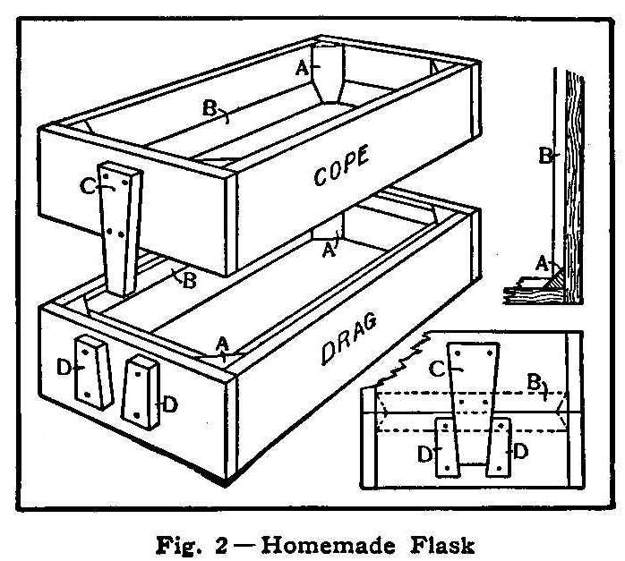
Fig. 2—Homemade Flask
The flask, J, Fig. 1, is shown more clearly in Fig. 2. It is made
of wood and is in two halves, the “cope,” or upper half, and the
“drag,” or lower part. A good way to make the flask is to take a
box, say 12 in. by 8 in. by 6 in. high, and saw it in half
longitudinally, as shown. If the box is not very strong, the
corners should be braced with triangular wooden strips, A A,
which should be nailed in, previous to sawing. The wooden strips
BB are used to hold the sand, which would otherwise slide out of
the flask when the two halves of the mold are separated.
The dowels, CC, are a very important part of the flask as upon
them depends the matching of the two halves of the mold. A
wedge-shaped piece, CC, is nailed to each end of the cope, and
the lower pieces, DD, are then nailed on the drag so that they
just touch C when the flask is closed. The two halves of the
flask will then occupy exactly the same relative position
whenever they are put together.
After the flask is done make two boards as shown at K, Fig. 1, a
little larger than the outside of the flask. A couple of cleats
nailed to each board will make it easier to pick up the mold when
it is on the floor.
A cast-iron glue-pot makes a very good crucible for melting the
metal, which can be either aluminum, white metal, zinc or any
other metal having a low melting-point. This completes the
equipment with the exception of one or two simple devices which
will now be described.
II—How to Make a Mold
Having finished making the flask and other equipment, as
described, everything will be ready for the operation of molding.
It would be well for those who have never had any experience in
this line to visit a small brass foundry, where they can watch
the molders at work, as it is much easier to learn by
observation; but they must not expect to make a good mold at the
first trial. The first attempt usually results in the sand
dropping out of the cope when it is being lifted from the drag,
either because of insufficient ramming around the edges or
because the sand is too dry.
A good way to tell when the sand is moist enough is to squeeze it
in the hand. If it forms into a cake and shows all the
finger-marks, it has a sufficient amount of moisture, but if it
crumbles or fails to cake it is too dry. An ordinary watering-pot
will be found useful in moistening the sand, but care should be
taken not to get it too wet, or the hot metal coming in contact
with it when the mold is poured will cause such rapid evaporation
that the mold will “boil” and make a poor casting. A little
practice in this operation will soon enable the molder to
determine the correct amount of moisture.
When molding with sand for the first time it will be necessary to
screen it all before using it, in order to remove the lumps, and
if water is added, the sand should be thoroughly shoveled until
the moisture is evenly distributed. The sand is then ready for
molding.
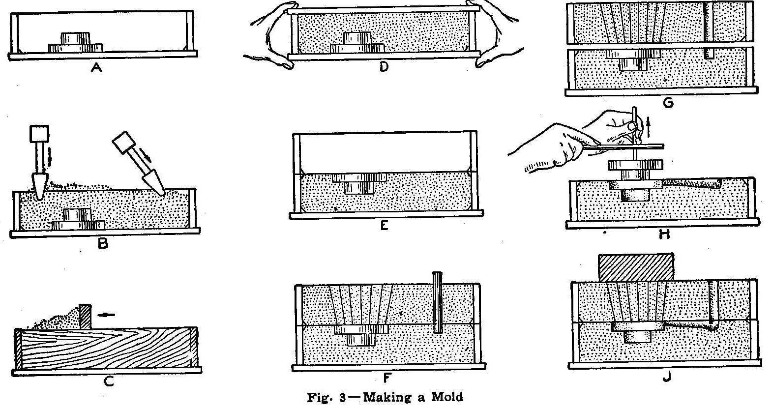
Fig. 3—Making a Mold
The operation of making a mold is as follows: The lower half of
the flask, or “drag,” and the pattern to be molded are both
placed on the cover board as shown at A. A quantity of sand
sufficient to completely cover the pattern is then sifted into
the drag, which is then filled level with the top with unscreened
sand. This is rammed down slightly with the rammer, and then more
sand is added until it becomes heaped up as shown at B. It is
then rammed again as before.
It is impossible to describe just how hard a mold should be
rammed, but by observing the results the beginner can tell when a
mold is too hard or too soft, and thus judge for himself. If the
sand falls out of the flask when lifting the cope, or if it opens
up or spreads after it is poured, it shows that the mold has been
rammed too little, and if the surface of the sand next to the
pattern is cracked it shows that the mold has been rammed too
hard. It will be found that the edges of the mold can stand a
little more ramming than the middle. In finishing the ramming,
pound evenly all over the surface with the blunt end of the
rammer.
After ramming, scrape off the surplus sand with a straight-edged
stick, as shown at C, and scatter about 1/16 in. of loose sand
over the surface for a good bearing. Place another cover board on
top, as shown at D, and by grasping with both hands, as shown,
turn the drag other side up. Remove the upper cover board and
place the upper half of the flask, or “cope,” in position, as
shown at E.
In order to prevent the two layers of sand sticking together, the
surface of the sand at E should be covered with coal-dust. This
is done by shaking the coal-dust bag over the flask, after which
the dust on the pattern may be removed by blowing. The cope is
then filled with sand and rammed in exactly the same manner as in
the case of the drag.
After the ramming is done a number of vent holes are made, as
shown at F, from the surface of the mold to the pattern, in order
to allow the escape of air and steam when the mold is being
poured. These vent holes may be made by pushing a wire about the
size of a knitting-needle down through the sand until it touches
the pattern. The “sprue,” or pouring-hole, is next cut, by means
of the sprue-cutter shown at the right, which consists of a piece
of thin brass or steel tubing about 3/4 in. in diameter.
Now comes the critical part of the molding operation—that of
lifting the cope from the drag. It is here that the amateur often
becomes discouraged, as the sand is liable to fall out of the
cope and spoil the mold; but with a little practice and patience
the molder can lift the cope every time without breaking it, as
shown at G.
The next operation is that of cutting the gate, which carries the
molten metal from the sprue to the opening left by the pattern.
This is done with a spoon, a channel being cut about 3/4 in. wide
and about 1/4 in. deep. The pattern is then drawn from the mold,
as shown at H, by driving a sharp pointed steel rod into the
pattern and lifting it from the sand. When a metal pattern is
used a thread rod is used, which is screwed into a tapped hole in
the pattern. Before drawing it is well to tap the drawing-rod
lightly with another and larger rod, striking it in all
directions and thus loosening the sand slightly from the pattern.
Some molders tap the pattern gently when withdrawing, as shown at
H, in order to loosen any sand which has a tendency to stick.
After drawing the pattern, place the cope back on the drag, as
shown at J. Place a brick or other flat, heavy object on top of
the mold above the pattern, to prevent the pressure of the melted
metal separating the two halves of the mold, and then pour.
III—Melting and Pouring
Having prepared one or more molds, the next operation is that of
melting and pouring. An ordinary cast-iron glue-pot makes a good
crucible and can be easily handled by a pair of tongs, made out
of steel rod, as shown in the sketch. In order to hold the tongs
together a small link can be slipped on over the handle, thus
holding the crucible securely.
A second piece of steel rod bent in the form of a hook at the end
is very useful for supporting the weight of the crucible and
prevents spilling the molten metal should the tongs slip off the
crucible. The hook is also useful for removing the crucible from
the fire, which should be done soon after the metal is entirely
melted, in order to prevent overheating. The metal should be
poured into the mold in a small stream, to give the air a chance
to escape, and should not be poured directly into the center of
the opening, as the metal will then strike the bottom hard enough
to loosen the sand, thus making a dirty casting.
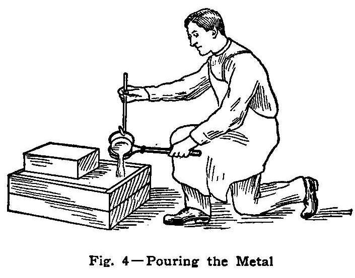
Fig. 4—Pouring the Metal
If, after being poured, the mold sputters and emits large volumes
of steam, it shows that the sand is too wet, and the castings in
such cases will probably be imperfect and full of holes.
A mold made in the manner previously described may be poured with
any desired metal, but a metal which is easily melted will give
the least trouble. One of the easiest metals to melt and one
which makes very attractive castings is pure tin. Tin melts at a
temperature slightly above the melting point of solder, and,
although somewhat expensive, the permanent brightness and
silver-like appearance of the castings is very desirable. A good
“white metal” may be made by mixing 75% tin, 15%
lead, 5% zinc
and 5% antimony. The object of adding antimony to an alloy is to
prevent shrinkage when cooling.
A very economical alloy is made by melting up all the old
type-metal, babbitt, battery zincs, white metal and other scrap
available, and adding a little antimony if the metal shrinks too
much in cooling. If a good furnace is available, aluminum can be
melted without any difficulty, although this metal melts at a
higher temperature than any of the metals previously mentioned.
In casting zincs for batteries a separate crucible, used only for
zinc, is very desirable, as the presence of a very small amount
of lead or other impurity
will cause the batteries to polarize. A
very good way to make the binding posts is to remove the binding
posts from worn-out dry batteries and place them in the molds in
such a way that the melted zinc will flow around them.
The time required for a casting to solidify varies with the size
and shape of the casting, but unless the pattern is a very large
one about five minutes will be ample time for it to set. The
casting is then dumped out of the mold and the sand brushed off.
The gate can be removed with either a cold chisel or a hacksaw,
and the casting is then ready for finishing.
Battery Switch
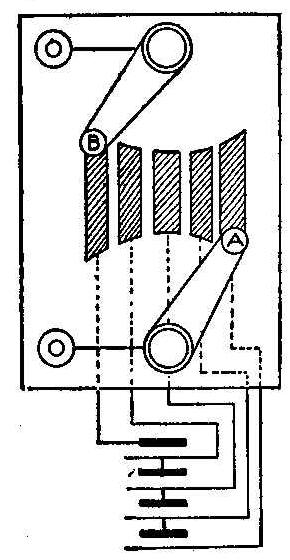
In cases where batteries are used in series and it is desirable
to change the strength and direction of the current frequently,
the following device will be found most convenient. In my own
case I used four batteries, but any reasonable number may be
used. Referring to the figure, it will be seen that by moving
the switch A toward the left the current can be reduced from four
batteries to none, and then by moving the switch B toward the
right the current can be turned on in the opposite direction to
the desired strength. In the various positions of these two
switches the current from each individual cell, or from any
adjacent pair of cells, may be used in either
direction.
Contributed by Harold S. Morton, Minneapolis.
An Optical Illusion
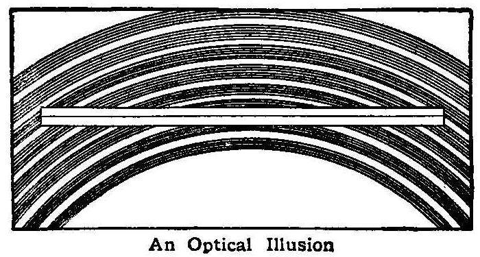
An Optical Illusion
The engraving shows a perfectly straight boxwood rule laid over a
number of turned brass rings of various sizes. Although the
effect in the illustration is less pronounced than it was in
reality, it will be noticed that the rule appears to be bent, but
sighting along the rule from one end will show that it is
perfectly straight.
The brass rings also appear distorted. The portions on one side
of the rule do not appear to be a continuation of those on the
other, but that they really are can be proved by sighting in the
same manner as before.
Contributed by Draughtsman, Chicago.
New Method of Lifting a Table
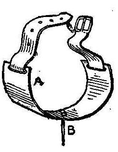
To perform this feat effectively the little device illustrated
will be required. To make it take a sheet-iron band, A, 3/4 in.
wide and attach a strap to fasten on the forearm between the
wrist and elbow. Put a sharp needle point, B, through the
sheet-iron so that it extends 3/4 in. outward. Make one of these
pieces for each arm.
In lifting the table first show the hands unprepared to the
audience and also a tight table, removing the cover to show that
the surface of the table is not prepared in any way. Then replace
the table, rest the hands upon it and at the same time press the
needle points in the arm pieces into the wood of the table, which
will be sufficient to hold it, says a correspondent of the
Sphinx. Then walk down among the audience.
How to Make a Paddle Boat
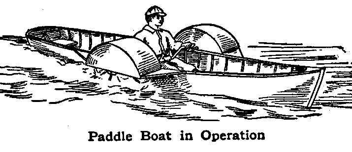
Paddle Boat in Operation
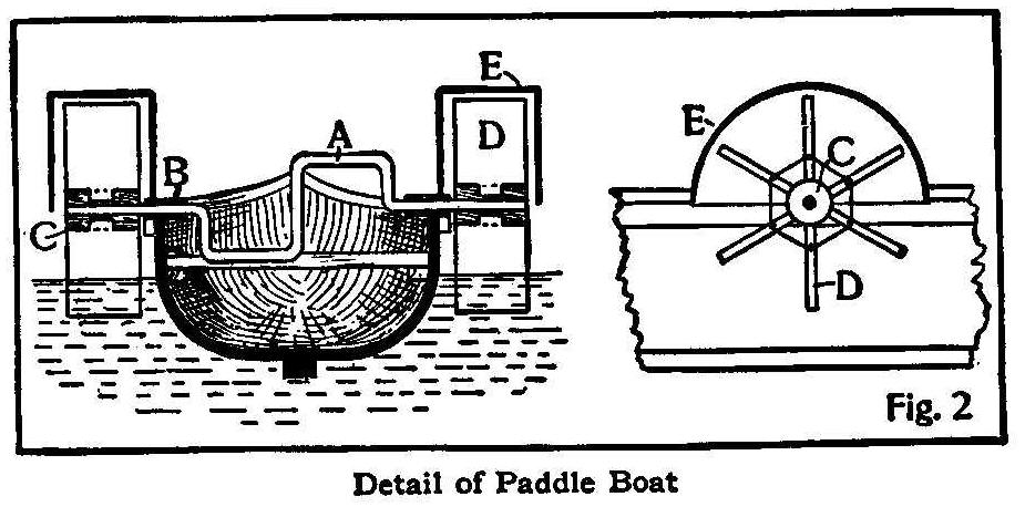
Detail of Paddle Boat
A rowboat has several disadvantages. The operation of the oars is
both tiresome and uninteresting, and the oarsman is obliged to
travel, backward. By replacing the oars with paddles, as shown in
the illustration, the operator can see where he is going and
enjoy the exercise much better than with oars. He can easily
steer the boat with his feet, by means of a pivoted stick in the
bottom of the boat, connected by cords to the rudder. At the
blacksmith shop have a 5/8-in. shaft made, as shown at A, Fig. 2.
It will be necessary to furnish a sketch giving all the
dimensions of the shaft, which should be designed to suit the
dimensions of the boat, taking care that sufficient clearance is
allowed, so that the cranks in revolving will not strike the
operator’s knees. If desired, split-wood handles may be placed on
the cranks, to prevent them from rubbing the hands.
The bearings, B, may be made of hardwood, but preferably of iron
pipe filled with melted babbitt. If babbitt is used, either
thoroughly smoke or chalk the shaft or wrap paper around it to
prevent the babbitt sticking. The pieces of pipe may be then
fastened to the boat by means of small pipe straps, such as may
be obtained at any plumber’s at a very small cost.
The hubs, C, should be made of wood, drilled to fit the shaft and
mortised out to hold the paddles, D. The covers, E, may be
constructed of thin wood or galvanized iron and should be braced
by triangular boards, as shown in Fig. 1. If galvanized iron is
used, it should be exposed to the weather two or three months
before painting, or the paint will come off, spoiling its
appearance.
Peculiar Properties of Ice
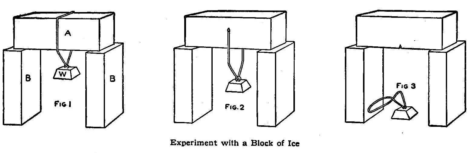
Experiment with a Block of Ice
Of all the boys who make snowballs probably few know what occurs
during the process. Under ordinary conditions water turns to ice
when the temperature falls to 32°, but when in motion, or under
pressure, much lower temperatures are required to make it a
solid. In the same way, ice which is somewhat below the freezing
point can be made liquid by applying pressure, and will remain
liquid until the pressure is removed, when it will again return
to its original state. Snow, being simply finely divided ice,
becomes liquid in places when compressed by the hands, and when
the pressure is removed the liquid portions solidify and unite
all the particles in one mass. In extremely cold weather it is
almost impossible to make a snowball, because a greater amount of
pressure is then required to make the snow liquid.
This process of melting and freezing under different pressures
and a constant temperature is well illustrated by the experiment
shown in Figs. 1, 2 and 3. A block of ice, A, Fig. 1, is
supported at each end by boxes BB, and a weight, W, is hung on a
wire loop which passes around the ice as shown. The pressure of
the wire will then melt the ice and allow the wire to sink down
through the ice as shown in Fig. 2. The wire will continue to cut
its way through the ice until it passes all the way through the
piece, as shown in Fig. 3. This experiment not only illustrates
how ice melts under pressure, but also how it solidifies when the
pressure is removed, for the block will still be left in one
piece after the wire has passed through.
Another peculiar property of ice is its
tendency to flow. It may seem strange that ice should flow like
water, but the glaciers of Switzerland and other countries are
literally rivers of ice. The snow which accumulates on the
mountains in vast quantities is turned to ice as a result of the
enormous pressure caused by its own weight, and flows through the
natural channels it has made in the rock until it reaches the
valley below. In flowing through these channels it frequently
passes around bends, and when two branches come together the
bodies of ice unite the same as water would under the same
conditions. The rate of flow is often very slow; sometimes only
one or two feet a day, but, no matter how slow the motion may be,
the large body of ice has to bend in moving.
This property of ice is hard to illustrate with the substance
itself, but may be clearly shown by sealing-wax, which resembles
ice in this respect. Any attempt to bend a piece of cold
sealing-wax with the hands results in breaking it, but by placing
it between books, as shown on page 65, or supporting it in some
similar way, it will gradually change from the original shape
A, and assume the shape shown at B.
Return-Call Bell With One Wire
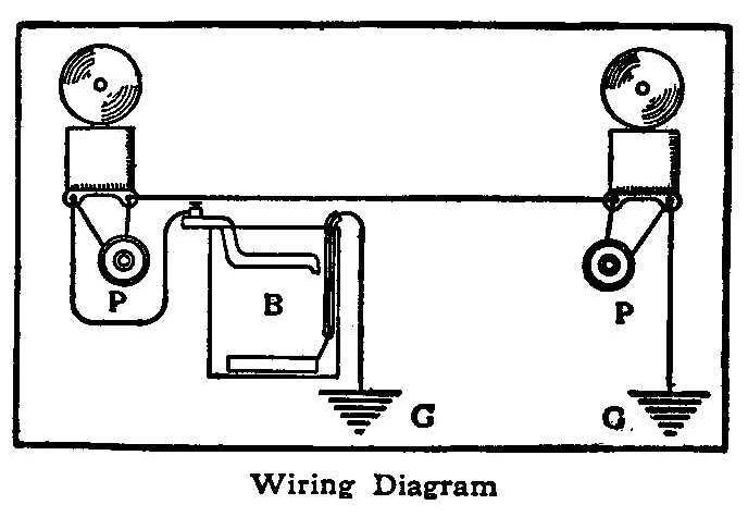
Wiring Diagram
To use only one wire for a return call bell connect up as shown
in the diagram, using a closed circuit or gravity battery, B. The
current is flowing through both bells all the time, the same as
the coils of a telegraph sounder, but is not strong enough to
ring both connected in series. Pressing either push button, P,
makes a short circuit of that bell and rings the one at the other
end of the line.
Contributed by Gordon T. Lane, Crafton, Pa.
Circuit Breaker for Induction Coils
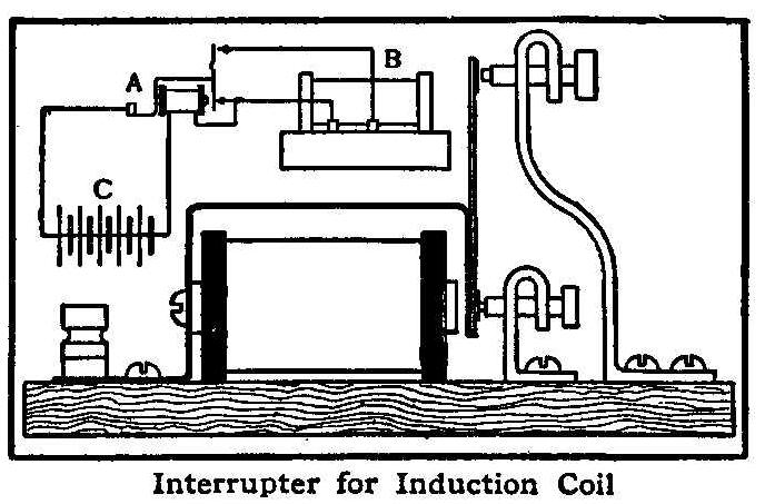
Interrupter for Induction Coil
Amateurs building induction coils are generally bothered by the
vibrator contacts blackening, thus giving a high resistance
contact, whenever there is any connection made at all. This
trouble may be done away with by departing from the old single-contact
vibrator and using one with self-cleaning contacts as
shown. An old bell magnet is rewound full of No. 26 double
cotton-covered wire and is mounted upon one end of a piece of
thin sheet iron 1 in. by 5 in. as per sketch. To the other end of
the strip of iron is soldered a piece of brass 1/64 in. by 1/4
in. by 2 in., on each end of which has been soldered a patch of
platinum foil 1/4 in. square.
The whole is connected up and mounted on a baseboard as per
sketch, the contact posts being of 1/16 in. by 1/2 in. brass, bent
into shape and provided with platinum tipped thumb screws. The
advantage of this style of an interrupter is that at each stroke
there is a wiping effect at the heavy current contact which
automatically cleans off any carbon deposit.
In the wiring diagram, A is the circuit breaker; B, the induction
coil, and C, the battery.
Contributed by A. G. Ward, Wilkinsburg, Pa.
Spit Turned by Water Power
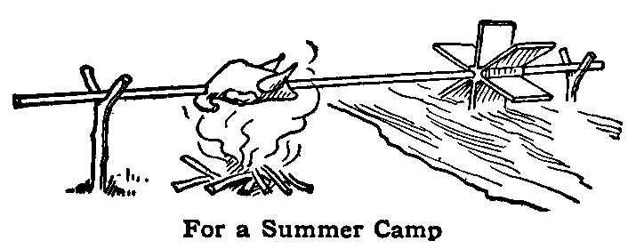
For a Summer Camp
Many of the Bulgarian peasants do their cooking in the open air
over bonfires. The illustration shows a laborsaving machine in
use which enables the cook to go away and leave meat roasting for
an hour at a time. The illustration shows how the spit to which
the meat is fastened is constantly turned by means of a slowly
moving water wheel. Some of our readers may wish to try the
scheme when camping out. The success depends upon a slow current,
for a fast-turning wheel will burn the meat.
A Short-Distance Wireless Telegraph
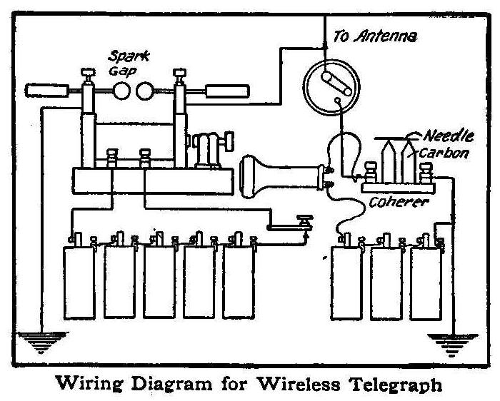
Wiring Diagram for Wireless Telegraph
The accompanying diagrams show a wireless-telegraph system that I
have used successfully for signaling a distance of 3,000 ft. The
transmitter consists of an induction coil, about the size used
for automobiles, a key or push-button for completing the circuit,
and five dry batteries. The small single-point switch is left
open as shown when sending a message, but when receiving it
should be closed in order that the electric waves from the
antenna may pass through the coherer. The coherer in this case is
simply two electric-light carbons sharpened to a wedge at one end
with a needle connecting the two, as shown. An ordinary telephone
receiver is connected in series with the coherer, as shown. To
receive messages hold the receiver to the ear and close the
switch, and answer by opening the switch and operating the key.
Contributed by Coulson Glick, Indianapolis.
Automatic Draft-Opener
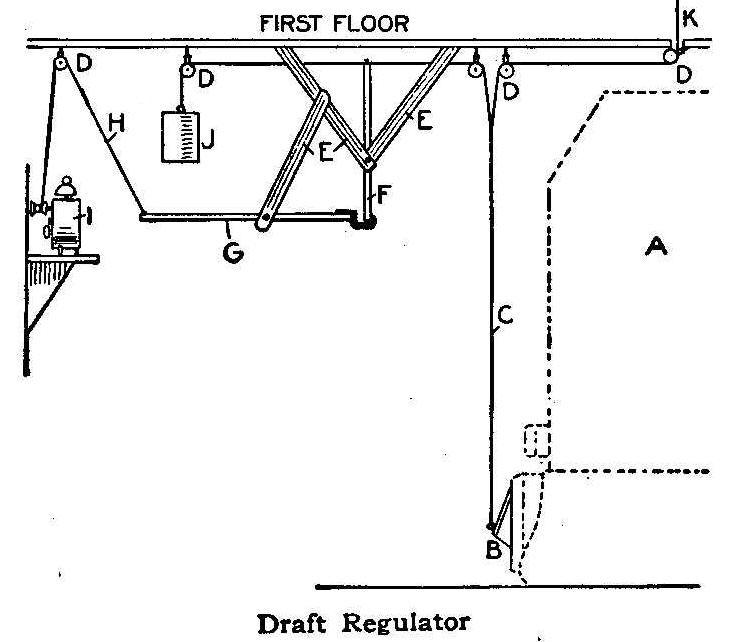
Draft Regulator
A simple apparatus that will open the draft of the furnace at any
hour desired is illustrated. The parts are: A, furnace; B,
draft; C, draft chain; D, pulleys; E, wooden supports; F,
vertical lever; G, horizontal lever; H, cord; I, alarm clock; J,
weight. K shows where and how the draft is regulated during the
day, the automatic device being used to open it early in the
morning. The spool on the alarm clock is fastened to the alarm
key by sawing a slit across the top of the spool and gluing it
on. When the alarm goes off a cord is wound up on the spool and
pulls the horizontal lever up, which releases the vertical lever
and allows the weight to pull the draft open.
Contributed by Gordon Davis, Kalamazoo, Mich.
A Window Conservatory
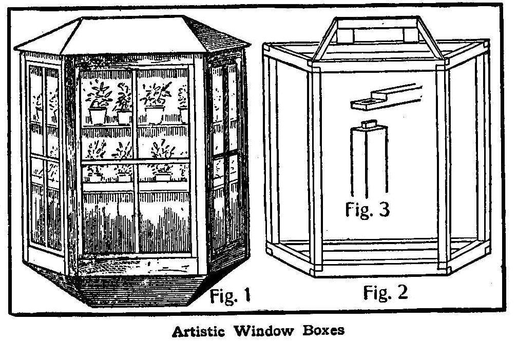
Artistic Window Boxes
During the winter months, where house plants are kept in the
home, it is always a question how to arrange them so they can get
the necessary light without occupying too much room.
The sketch shows how a neat window conservatory may be made at
small cost that can be fastened on the house just covering a
window, which will provide a fine place for the plants. The frame
(Fig. 2) is made of about 2 by 2-in. material framed together as
shown in Fig. 3. This frame should be made with the three
openings of such a size that a four-paned sash, such as used for
a storm window, will fit nicely in them. If the four vertical
pieces that are shown in Fig. 2 are dressed to the right angle,
then it will be easy to put on the finishing corner boards that
hold the sash.
The top, as well as the bottom, is constructed with two small
pieces like the rafters, on which is nailed the sheathing boards
and then the shingles on top and the finishing boards on the
bottom.
How to Make an Electroscope
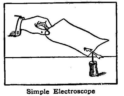
Simple Electroscope
An electroscope for detecting electrified bodies may be made out
of a piece of note paper, a cork and a needle. Push the needle
into the cork, and cut the paper in the shape of a small arrow.
Balance the arrow on the needle as shown in the sketch, and the
instrument will then be complete. If a piece of paper is then
heated over a lamp or stove and rubbed with a piece of cloth or a
small broom, the arrow will turn when the paper is brought near
it.
Contributed by Wm. W. Grant, Halifax, N. S., Canada.
Miniature Electric Lighting
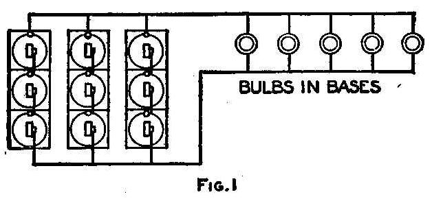
Fig. 1
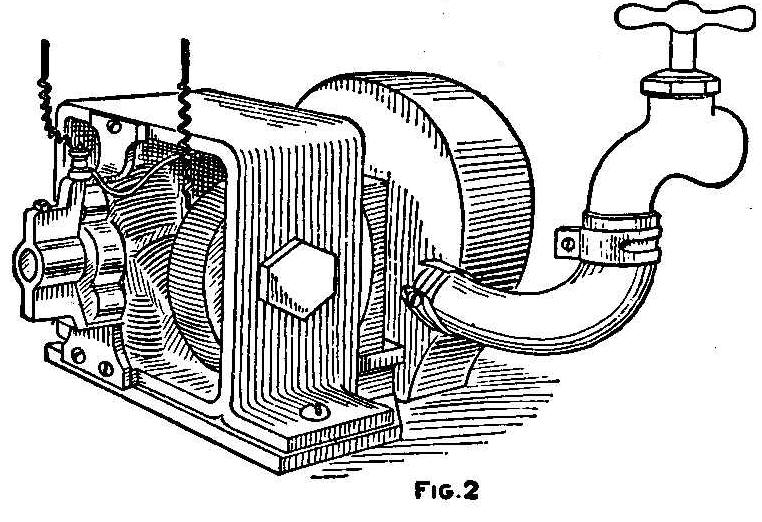
Fig. 2
Producing electric light by means of small bulbs that give from
one-half to six candle power, and a suitable source of power, is
something that will interest the average American boy.
These circular bulbs range from 1/4 to 2 in. in diameter, and
cost 27 cents each complete with base. They are commonly known as
miniature battery bulbs, since a battery is the most popular
source of power. The 1/2-cp. bulbs are usually 2-1/2 volts and
take 1/4 ampere of current. It requires about three medium dry
cells to operate it. However, there is now upon the market a
battery consisting of 3 small dry cells connected in series, put
up in a neat case with 2 binding posts, which sells for 25 cents.
This is more economical than dry cells, as it gives about 4 volts
and 3 amperes. It will run as large a lamp a 3-1/2 volts, 1 cp.,
for some time very satisfactorily. More than one lamp can be run
by connecting the bulbs in parallel, as indicated by Fig. 1,
which shows the special battery with 3 dry cells in the case, and
the 2 binding posts for connection with the bulbs. In this case
it is also advisable to connect several batteries in parallel
also, so as to increase the current, but maintain the voltage
constant. Thus the individual cells are in multiple series, i.
e., multiples of series of three. By keeping in mind the ampere
output of the battery and rating of the lamp, one can regulate
the batteries as required. It must be remembered, in this
connection, that any battery which is drawn upon for half of its
output will last approximately three times as long, as if drawn
upon for its total output. Thus, in any system of lamps, it is
economical to provide twice as many batteries as necessary. This
also supplies a means of still maintaining the candle power when
the batteries are partially exhausted, by connecting them in
series. However, this must be done with very great caution, as
the lights will be burnt out if the voltage is too high.
Persons living in the city will find an economical means of
lighting lamps by securing exhausted batteries from any garage,
where they are glad to have them taken away. A certain number of
these, after a rest, can be connected up in series, and will give
the proper voltage.
In conclusion, for battery power: Connecting batteries in series
increases the voltage, and slightly cuts down the current or
amperage, which is the same as that of one battery; while
connecting batteries in parallel increases the amperage, but
holds the voltage the same as that of one cell. Thus, if the
voltage and amperage of any cell be known, by the proper
combination of these, we can secure the required voltage and
amperage to light any miniature lamp. And it might be said that
dry cells are the best for this purpose, especially those of low
internal resistance.
For those having a good water supply there is a more economical
means of maintenance, although the first cost is greater. Fig. 2
shows the scheme. A small dynamo driven by a water motor attached
to a faucet, generates the power for the lights. The cost of the
smallest outfit of the kind is about $3 for the water motor and
$4 for the dynamo. This dynamo has an output of 12 watts, and
will produce from 18 to 25 cp., according to the water pressure
obtainable. It is advisable to install the outfit in the
basement, where the water pressure is the greatest, and then lead
No. 18 B & S. double insulated wire wherever needed. The dynamo
can also be used as a motor, and is wound for any voltage up to
ten. The winding should correspond to the voltage of the lamps
which you desire to run. However, if wound for 6 volts, one could
run parallel series of two 3-volt, 1-cp. lamps; making, as in
Fig. 3, 11 series, or 22 lights. If wound for 10 volts, it would
give 1-1/4 amperes and run four 6-cp. lamps. Thus, it will be
seen that any candle power lamp can be operated by putting the
proper number of lights in each series, and running the series in
parallel. So, to secure light by this method, we simply turn on
the water, and the water consumption is not so great as might be
imagined.
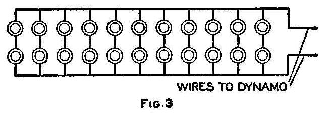
Fig. 3
For the party who has electric light in his house there is still
an easier solution for the problem of power. If the lighting
circuit gives 110 volts he can connect eleven 10-volt lamps in
series. These will give 3 cp. each, and the whole set of 11 will
take one ampere of current, and cost about the same as a 32-cp.
lamp, or 1-1/4 cents per hour. Simply connect the miniature
circuit to an Edison plug, and insert in the nearest lamp socket.
Any number of different candle power lamps can be used providing
each lamp takes the same amount of current, and the sum of their
voltages equals the voltage of the circuit used. This arrangement
of small lights is used to produce a widely distributed, and
diffused light in a room, for display of show cases, and for
Christmas trees. Of all these sources of power the two last are
the most economical, and the latter of these two has in its favor
the small initial cost. These lamps are by no means playthings or
experiments, but are as serviceable and practical as the larger
lamps.
Contributed by Lindsay Eldridge, Chicago.
How to Make a New Language
Anyone possessing a phonograph can try a very interesting and
amusing experiment without going to any expense. Remove the belt
and replace with a longer one, which can be made of narrow braid
or a number of strands of yarn. The new belt should be long
enough to allow crossing it, thus reversing the machine. This
reverses every sound on the record and changes it to such an
extent that very few words can be recognized.
How to Make a Cup-and-Saucer Rack
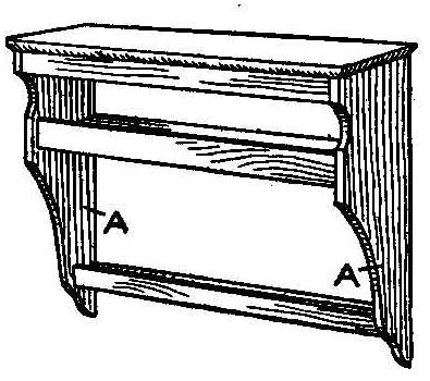
The rack is made of any suitable kind of wood, and the sides, A,
are cut just alike, or from one pattern. The shelves are made in
various widths to fit the sides at the places where they are
wanted. The number of shelves can be varied and to suit the size
of the dishes. Cup hooks are placed on top and bottom shelves. It
is hung on the wall the same as a picture from the molding.
Contributed by F. B. Emig, Santa Clara, Cal.
Reversing a Small Motor
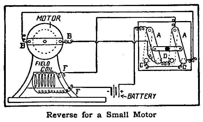
Reverse for a Small Motor
All that is necessary for reversing the motor is a pole-changing
switch. Connect the two middle posts of the switch with each
other and the two outside posts with each other. Then connect one
of the outside posts of the switch to one brush of the motor and
one middle post to the other brush.
Connect one bar of the switch to one end of the field coil and
the other bar to one pole of the battery, and connect the other
pole of the battery to the other field coil. To reverse the
motor, simply change the switch.
Referring to the illustration, the letters indicate as follows:
FF, field of motor; BB, brushes of motor; AA, bars of
pole-changing switch; DD, center points of switch; CC, outside
points of switch.
Contributed by Leonard E. Parker, Plymouth, Ind.
To Drive Away Dogs
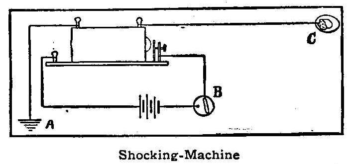
Shocking-Machine
The dogs in my neighborhood used to come around picking up
scraps. After I connected up my induction coil, as shown in the
sketch, we were not bothered with them. A indicates the ground;
B, switch; and C, a bait of meat, or a tempting bone.
Contributed by Geo. W. Fry, 903 Vine St., San Jose, Cal.
An Automatic Lock
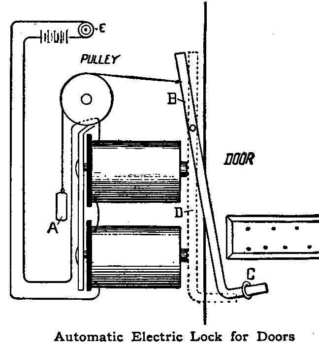
Automatic Electric Lock for Doors
The illustration shows an automatic lock operated by electricity,
one cell being sufficient. When the circuit is broken a weight,
A, attached to the end of the armature B, tends to push the other
end of the armature into the screw eye or hook C, which is in the
door, thus locking the door.
To unlock the door, merely push the button E, The magnet then
draws the armature out of the screw eye and the door is unlocked.
The dotted line at D shows the position of the armature when the
circuit is complete and the door unlocked. The weight must be in
proportion to the strength of the magnet. If it is not, the door
will not lock, or would remain locked. The button can be hidden,
as it is the key to the lock.
Contributed by Claude B. Melchior, Hutchinson, Minn.
Experiment with Two-Foot Rule and Hammer
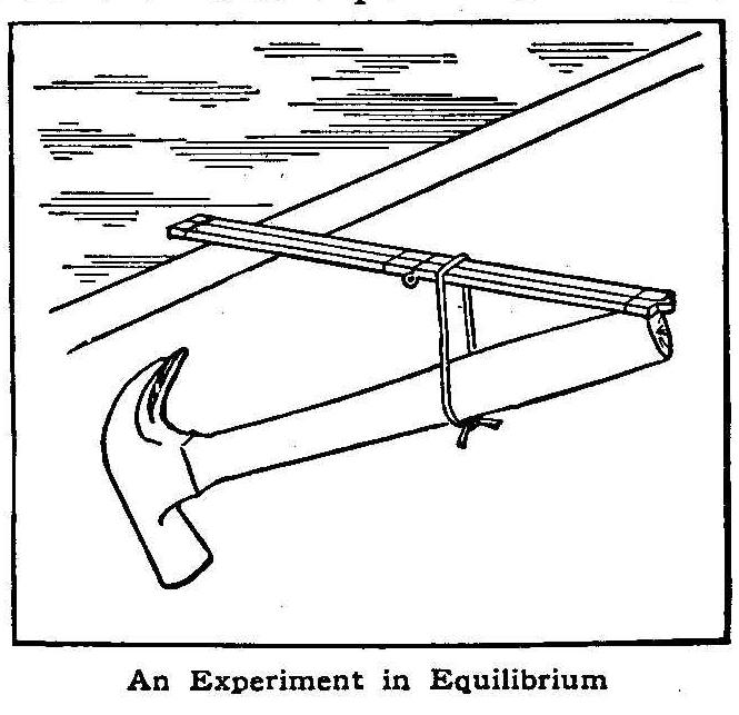
An Experiment in Equilibrium
An example of unstable equilibrium is shown in the accompanying
sketch. All that is needed is a 2-foot rule, a hammer, a piece of
string, and a table or bench. The experiment works best with a
hammer having a light handle and a very heavy head. Tie the ends
of the string together, forming a loop, and pass this around the
hammer handle and rule. Then place the apparatus on the edge of
the table, where it will remain suspended as shown.
Contributed by Geo. P. Schmidt, Culebra, Porto Rico, W. I.
Simple Current Reverser
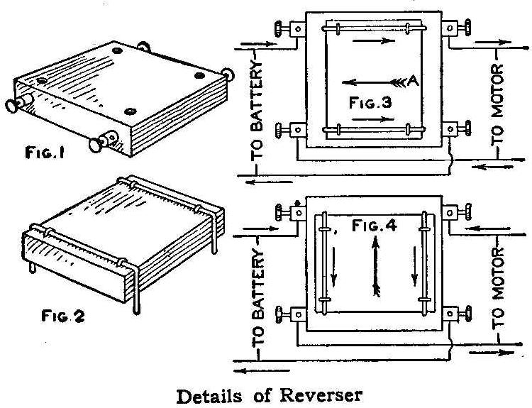
Details of Reverser
On a block of hardwood draw a square (Fig. 1) and drill a hole in
each corner of the square. Fill these holes with
mercury and
connect them to four binding posts (Fig. 1).
On another block of wood fasten two wires, as shown in Fig. 2, so
that their ends can be placed in the holes in the first block.
Then connect up with the motor and battery as in Fig. 3. When the
block is placed on with the big arrow A pointing in the direction
indicated in Fig. 3, the current flows with the small arrows. To
reverse turn through an angle of 90 degrees (Fig. 4).
Contributed by F. Crawford Curry, Brockville, Ontario, Canada.
Alarm Clock to Pull up Furnace Draft
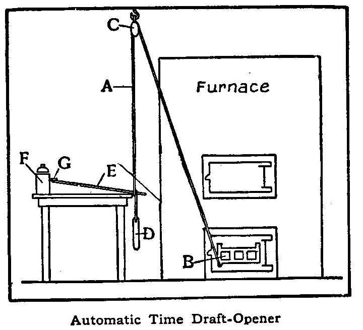
Automatic Time Draft-Opener
A stout cord, A, is attached to the draft B of the furnace, run
through a pulley, C, in the ceiling and has a window weight, D,
attached at the other end. A small stick is put through a loop in
the cord at about the level of the table top on which the alarm
clock F stands. The other end of stick E is placed under the key
G of the alarm clock. When the alarm rings in the early morning,
the key turns, the stick falls away, releasing the weight, which
pulls the draft open.
Contributed by Edward Whitney, 18 Gorham St., Madison, Wis.
How to Transmit Phonograph Music to a Distance
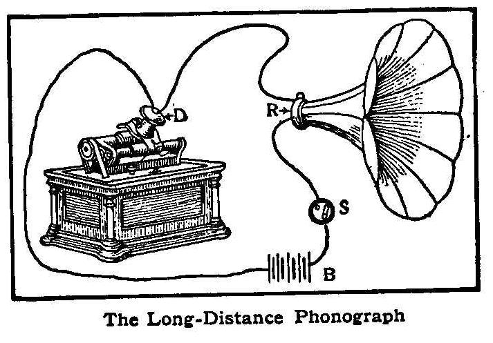
The Long-Distance Phonograph
An interesting experiment, and one calculated to mystify anyone
not in the secret, is to transmit the music or speech from a
phonograph to another part of the house or even a greater
distance. For an outdoor summer party the music can be made to
come from a bush, or tree, or from a bed of flowers. The
apparatus is not difficult to construct.
The cut shows the arrangement. Procure a long-distance telephone
transmitter, D, including the mouthpiece, and fasten it to the
reproducer of the phonograph. Also a watch case receiver, R,
which fasten to the horn. These parts may be purchased from any
electrical-supply house. Connect two wires to the transmitter,
running one direct to the receiver, and the other to the battery,
thence to a switch, S, and then to the receiver. The more
batteries used the louder will be the sound produced by the horn,
but avoid using too much battery or the receiver is apt to heat.
Contributed by Wm. J. Farley, Jr., Camden, N. J.
How to Make a Telescope
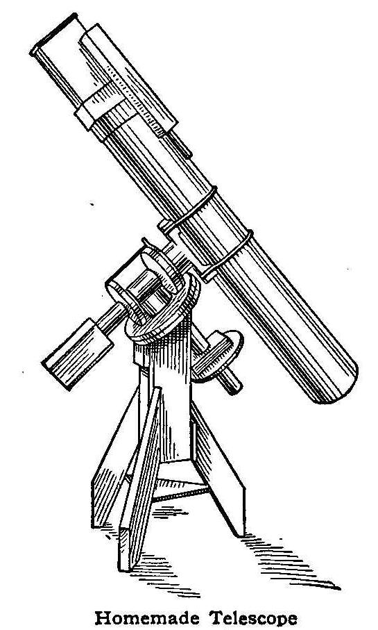
Homemade Telescope
With a telescope like the one here described, made with his own
hands, a farmer boy not many years ago discovered a comet which
had escaped the watchful eyes of many astronomers. First, get two
pieces of plate glass, 6 in. square and 1 in. thick, and break
the corners off to make them round, grinding the rough edges on a
grindstone. Use a barrel to work on, and fasten one glass on the
top of it in the center by driving three small nails at the sides
to hold it in place. Fasten, with pitch, a round 4-in. block of
wood in the center on one side of the other glass to serve as a
handle.
Use wet grain emery for coarse grinding. Take a pinch and spread
it evenly on the glass which is on the barrel, then take the
glass with the handle and move it back and forth across the lower
glass, while walking around the barrel; also rotate the glass,
which is necessary to make it grind evenly. The upper glass or
speculum always becomes concave, and the under glass or tool
convex.
Work with straight strokes 5 or 6 in. in length; after working 5
hours hold the speculum in the sunshine and throw the rays of the
sun onto a paper; where the rays come to a point gives the focal
length. If the glass is not ground enough to bring the rays to a
point within 5 ft., the coarse grinding must be continued, unless
a longer focal length is wanted.
Have ready six large dishes, then take 2 lb. flour emery and mix
in 12 qt. of water; immediately turn the water into a clean dish
and let settle 30 seconds; then turn it into another dish and let
settle 2 minutes, then 8 minutes, 30 minutes and 90 minutes,
being careful not to turn off the coarser emery which has
settled. When dry, turn the emery from the 5 jars into 5 separate
bottles, and label. Then take a little of the coarsest powder,
wetting it to the consistency of cream, and spread on the glass,
work as before (using short straight strokes 1-1/2 or 2 in.)
until the holes in the glass left by the grain emery are ground
out; next use the finer grades until the pits left by each
coarser grade are ground out. When the two last grades are used
shorten the strokes to less than 2 in. When done the glass should
be semi-transparent, and is ready for polishing.
When polishing the speculum, paste a strip of paper 1-1/3 in.
wide around the convex glass or tool, melt 1 lb. of pitch and
turn on to it and press with the wet speculum. Mold the pitch
while hot into squares of 1 in., with 1/4-in. spaces, as in Fig.
1. Then warm and press again with the speculum, being careful to
have all the squares touch the speculum, or it will not polish
evenly. Trim the paper from the edge with a sharp knife, and
paint the squares separately with jeweler’s rouge, wet till soft
like paint. Use a binger to spread it on with. Work the speculum
over the tool the same as when grinding, using straight strokes 2
in. or less.
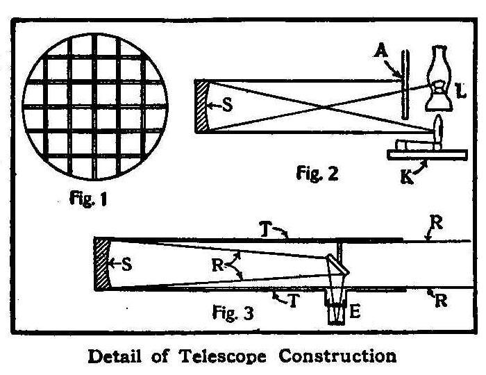
Detail of Telescope Construction
When the glass is polished enough to reflect some light, it
should be tested with the knife-edge test. In a dark room, set
the speculum against the wall, and a large lamp, L, Fig. 2, twice
the focal length away. Place a large sheet of pasteboard, A, Fig.
2, with a small needle hole opposite the blaze, by the side of
the lamp, so the light from the blaze will shine onto the glass.
Place the speculum S, Fig. 2, so the rays from the needle hole
will be thrown to the left side of the lamp (facing the
speculum), with the knife mounted in a block of wood and edgeways
to the lamp, as in K, Fig. 2. The knife should not be more than 6
in. from the lamp. Now move the knife across the rays from left
to right, and look at the speculum with the eye on the right side
of the blade. When the focus is found, if the speculum is ground
and polished evenly it will darken evenly over the surface as the
knife shuts off the light from the needle hole. If not, the
speculum will show some dark rings, or hills. If the glass seems
to have a deep hollow in the center, shorter strokes should be
used in polishing; if a hill in the center, longer strokes. The
polishing and testing done, the speculum is ready to be silvered.
Two glass or earthenware dishes, large enough to hold the
speculum and 2 in. deep, must be procured. With pitch, cement a
strip of board 8 in. long to the back of the speculum, and lay
the speculum face down in one of the dishes; fill the dish with
distilled water, and clean the face of the speculum with
nitric acid,
until the water will stick to it in an unbroken film.
The recipe for silvering the speculum is:
| Solution A: | |
| Distilled water | 4 oz. |
| Silver nitrate | 100 gr. |
| Solution B: | |
| Distilled water | 4 oz. |
| Caustic stick potash (pure by alcohol) | 100 gr. |
| Solution C: | |
| Aqua Ammonia. | |
| Solution D: | |
| Sugar loaf | 840 gr. |
| Nitric acid | 39 gr. |
| Alcohol (Pure) | 25 gr. |
Mix solution D and make up to 25 fluid oz. with distilled water,
pour into a bottle and carefully put away in a safe place for
future use, as it works better when old:
Now take solution A and set aside in a small bottle one-tenth of
it, and pour the rest into the empty dish; add the ammonia
solution drop by drop; a dark brown precipitate will form and
subside; stop adding ammonia solution as soon as the bath clears.
Then add solution B, then ammonia until bath is clear. Now add
enough of the solution A, that was set aside, to bring the bath
to a warm saffron color without destroying its transparency. Then
add 1 oz. of solution D and stir until bath grows dark. Place the
speculum, face down, in the bath and leave until the silver
rises, then raise the speculum and rinse with distilled water.
The small flat mirror may be silvered the same way. When dry, the
silver film may be polished with a piece of chamois skin, touched
with rouge, the polishing being accomplished by means of a light
spiral stroke.
Fig. 3 shows the position of the glasses in the tube, also how
the rays R from a star are thrown to the eyepiece E in the side
of the tube. Make the tube I of sheet iron, cover with paper and
cloth, then paint to make a non-conductor of heat or cold. Make
the mounting of good seasoned lumber.
Thus an excellent 6-in. telescope can be made at home, with an
outlay of only a few dollars. My telescope is 64 in. long and
cost me just $15, but I used all my spare time in one winter in
making it. I first began studying the heavens through a spyglass,
but an instrument such as I desired would cost $200—more than I
could afford. Then I made the one described, with which I
discovered a new comet not before observed by
astronomers.
John E. Mellish.
How to Make “Freak” Photographs
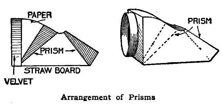
Arrangement of Prisms
The “freak” pictures of well-known people which were used by some
daily newspapers recently made everybody wonder how the distorted
photographs were made. A writer in Camera Craft gives the secret,
which proves to be easy of execution. The distortion is
accomplished by the use of prisms, as follows: Secure from an
optician or leaded-glass establishment, two glass prisms,
slightly wider than the lens mount. The flatter they are the less
they will distort. About 20. deg. is a satisfactory angle. Secure
them as shown by the sectional sketch, using strawboard and black
paper. Then make a ring to fit over the lens mount and connect it
with the prisms in such a way as to exclude all light from the
camera except that which passes through the face of the prisms.
The inner surface of this hood must be dull black. The paper
which comes around plates answers nicely. If the ring which slips
over the lens mount is lined with black velvet, it will exclude
all light and hold firmly to the mount, Place over lens, stop
down well after focusing, and proceed as for any picture.
Another Electric Lock
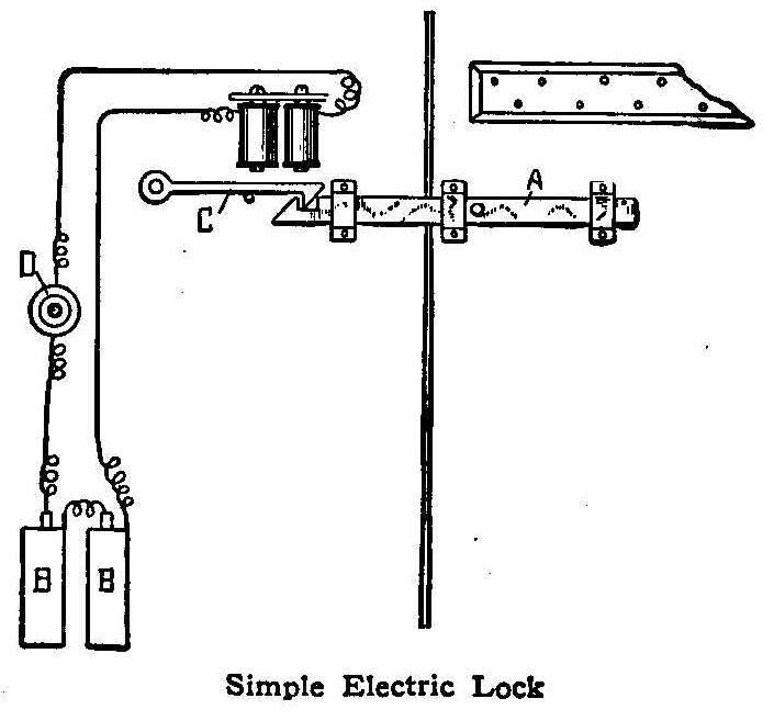
Simple Electric Lock
The details of the construction of an electrically operated lock
are shown in the illustration. When the door is closed and the
bolt A pushed into position, it automatically locks. To unlock,
push the button D, which act will cause the electromagnet to
raise the latch C, when the bolt may be drawn and the door
opened.
Contributed by A. D. Zimmerman, Boody, Ill.
How to Mix Plaster of Paris
For the mixing of plaster of Paris for any purpose, add the
plaster gradually to the water, instead of the contrary, says the
Master Painter. Do not stir it, just sprinkle it in until you
have a creamy mass without lumps. Equal parts of plaster and
water is approximately the correct proportion. The addition of a
little vinegar or glue water will retard the setting of the
plaster, but will not preserve its hardening. Marshmallow powder
also retards the setting. In this way the plaster may be handled
a long time without getting hard. If you wish the plaster to set
extra hard, then add a little sulphate of potash, or powdered
alum.
Enlarging with a Hand Camera
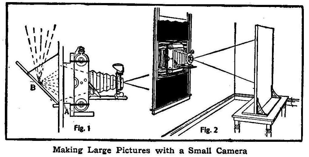
Making Large Pictures with a Small Camera
Everyone who owns a hand camera has some pictures he would like
enlarged. It is not necessary to have a large camera to do this,
as the process is exceedingly simple to make large pictures from
small negatives with the same hand camera.
A room from which all light may be excluded and a window through
which the light can enter without obstruction from trees or
nearby buildings, with a shelf to hold the camera and a table
with an upright drawing-board attached, complete the arrangement.
The back is taken out of the camera and fitted close against the
back of the shelf, which must be provided with a hole the same
size and shape as the opening in the back of the camera. The
negative used to make the enlarged print is placed in the shelf
at A, Fig. 1. The rays of the clear, unobstructed light strike
the mirror, B, and reflect through the negative, A, through the
lens of the camera and on the board, as shown in Fig. 2. The
window must be darkened all around the shelf.
After placing the negative and focusing the lens for a clear
image on the board, the shutter is set and a bromide paper is
placed on the board. The paper is exposed, developed and fixed by
the directions that are enclosed in the package of bromide
papers.
Positioning A Hanging Lamp
Don’t pull a lamp hung by flexible cord to one side with a wire
and then fasten to a gas pipe. I have seen a wire become red hot
in this manner. If the lamp hung by a cord must be pulled over,
use a string.
A Curious Compressed Air Phenomenon
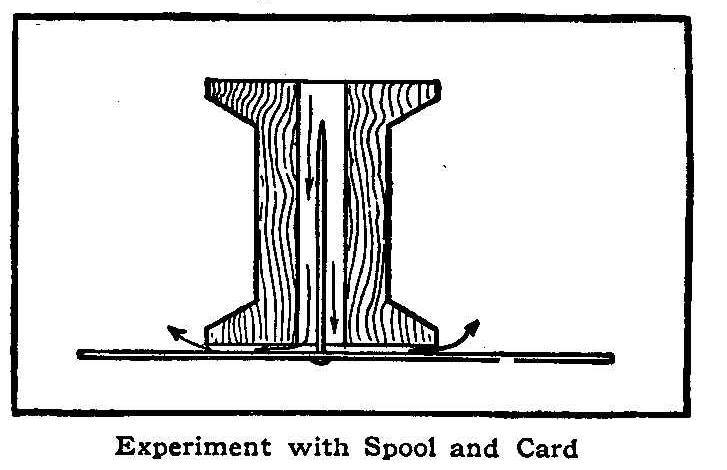
Experiment with Spool and Card
Push a pin through an ordinary business card and place the card
against one end of a spool with the pin inside the bore, as shown
in the sketch. Then blow through the spool, and it will be found
that the card will not be blown away, but will remain suspended
without any visible support. This phenomenon is explained by the
fact that the air radiates from the center at a velocity which is
nearly constant, thereby producing a partial vacuum between the
spool and the card. Can the reader devise a practical application
of this contrivance?
Simple Switch for Reversing a Current
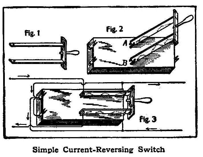
Simple Current-Reversing Switch
Take two strips of copper or brass and fasten them together by
means of gutta-percha (Fig. 1); also provide them with a handle.
Saw out a rectangular block about one and one-half times as long
as the brass strips and fasten to it at each end two forked
pieces of copper or brass, as in Fig. 2. Fasten on the switch
lever, as at A and B, Fig. 2, so that it can rotate about these
points. Connect the wires as shown in Fig. 3. To reverse, throw
the lever from one end of the block to the other.
Contributed by R. L. Thomas, San Marcos, Tex.
Novel Mousetrap
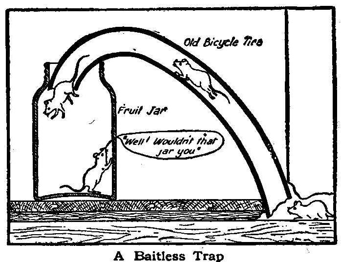
A Baitless Trap
A piece of an old bicycle tire and a glass fruit jar are the only
materials required for making this trap. Push one end of the tire
into the hole, making sure that there is a space left at the end
so that the mice can get in. Then bend the other end down into a
fruit jar or other glass jar. Bait may be placed in the jar if
desired, although this is not necessary.
Contributed by Geo. G. McVicker, North Bend, Neb.
Polishing Nickel
A brilliant polish may be given to tarnished nickel by immersing
in alcohol and 2 per cent of
sulphuric acid from 5 to 15 seconds.
Take out, wash in running water, rinse in alcohol, and rub dry
with linen cloth.
Homemade Arc Light
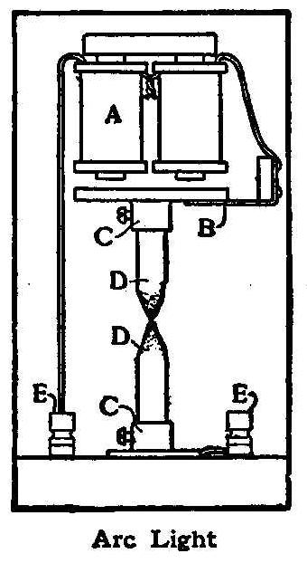
Arc Light
By rewinding an electric-bell magnet with No. 16 wire and
connecting it in series with two electric-light carbons, as shown
in the sketch, a small arc will be formed between the carbon
points when the current is applied. In the sketch, A is the
electric-bell magnet; B, the armature; C C, carbon sockets; D,
carbons, and E E, binding posts. When connected with 10 or 12 dry
batteries this lamp gives a fairly good light.
Contributed by Morris L. Levy, San Antonio, Tex.
Lighting an Incandescent Lamp with an Induction Coil
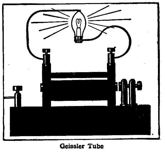
Geissler Tube
An incandescent lamp of low candlepower may be illuminated by
connecting to an induction coil in the manner shown in the
sketch. One wire is connected to the metal cap of the lamp and
the other wire is fastened to the glass tip. If the apparatus is
then placed in the dark and the current turned on, a peculiar
phosphorescent glow will fill the whole interior of the lamp. The
induction coil used for this purpose should give a spark about
1/2 in. long or more.
Contributed by Joseph B. Bell, Brooklyn.
How to Make a Jump-Spark Coil
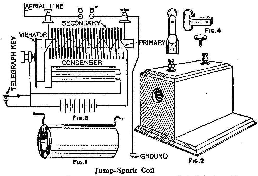
Jump-Spark Coil
The induction coil is probably the most popular piece of
apparatus in the electrical laboratory, and particularly is it
popular because of its use in experimental wireless telegraphy.
Ten years ago wireless telegraphy was a dream of scientists;
today it is the plaything of school-boys and thousands of
grown-up boys as well.
Divested of nearly all technical phrases, an induction coil may
be briefly described as a step-up transformer of small capacity.
It comprises a core consisting of a cylindrical bundle of
soft-iron wires cut to proper length. By means of two or more
layers of No. 14 or No. 16 magnet wire, wound evenly about this
core, the bundle becomes magnetized when the wire terminals are
connected to a source of electricity.
Should we now slip over this electromagnet a paper tube upon
which has been wound with regularity a great and continuous
length of No. 36 magnet wire, it will be found that the lines of
force emanating from the energized core penetrate the new
coil-winding almost as though it were but a part of the surrounding
air itself, and when the battery current is broken rapidly a
second electrical current is said to be induced into the second
coil or secondary.
All or any of the parts of an induction coil may be purchased
ready-made, and the first thing to do is to decide which of the
parts the amateur mechanic can make and which would be better to
buy ready-made. If the builder has had no experience in
coil-winding it would probably pay to purchase the secondary coil
ready-wound, as the operation of winding a mile or more of fine
wire is very difficult and tedious, and the results are often
unsatisfactory. In ordering the secondary it is always necessary
to specify the length of spark desired.
The following method of completing a 1-in. coil illustrates the
general details of the work. The same methods and circuits apply
to small and larger coils. The ready-made secondary is in solid
cylindrical form, about 6 in. long and 2-5/8 in. diameter, with a
hole through the winding 1-1/4 in. in diameter, as shown in Fig.
1. The secondary will stand considerable handling without fear of
injury, and need not be set into a case until the primary is
completed. The primary is made of fine annealed No. 24 iron wire
cut 7 in. or 8 in. in length, as the maker prefers, and bundled
to a diameter of 7/8 in. The wires may be straightened by rolling
two or three at a time between two pieces of hard wood. If the
amateur has difficulty in procuring this wire, the entire core
may be purchased ready-made.
After the core wires are bundled, the core is wrapped with one or
two layers of manila paper. The straighter the wire the more iron
will enter into the construction of the core, which is desirable.
Beginning half an inch from one end, No. 16 cotton-covered
magnet wire is wound from one end to the other evenly and then
returned, making two layers, and the terminals tied down to the
core with twine. Core and primary are then immersed in boiling
paraffine wax to which a small quantity of resin and beeswax has
been added. This same wax may be used later in sealing the
completed coil into a box. Over this primary is now wrapped one
layer of okonite tape, or same thickness of heavily shellacked
muslin. This completed primary will now allow of slipping into
the hole in the secondary.
Should the secondary have been purchased without a case, a wooden
box of mahogany or oak is made, large enough to contain the
secondary and with an inch to spare all around, with room also
for a small condenser; but if it is not convenient to do this
work, a box like that shown in Fig. 2 may be purchased at a small
cost. A 7/8-in. hole is bored in the center of one end, through
which the primary core projects 1/8 in. This core is to be used
to attract magnetically the iron head of a vibrating interrupter,
which is an important factor of the coil. This interrupter is
shaped as in Fig. 4, and is fastened to the box in such a way
that the vibrator hammer plays in front of the core and also that
soldered connections may be made inside the box with the screws
used in affixing the vibrator parts to the box. The condenser is
made of four strips of thin paper, 2 yd. long and 5 in. wide, and
a sufficient quantity of tinfoil. When cut and laid in one
continuous length, each piece of tin-foil must overlap the
adjoining piece a half inch, so as to form a continuous
electrical circuit. In shaping the condenser, one piece of the
paper is laid down, then the strip of tin-foil, then two strips
of paper and another layer of foil, and finally the fourth strip
of paper. This makes a condenser which may be folded, beginning
at one end and bending about 6 in. at a time. The condenser is
next wrapped securely with bands of paper or tape, and boiled in
pure paraffine wax for one hour, after which it is pressed under
considerable weight until firm and hard. One of the sheets of
tin-foil is to form one pole of the condenser, and the other
sheet, which is insulated from the first, forms the other pole or
terminal. (This condenser material is purchasable in long strips,
ready for assembling.)
The wiring diagram, Fig. 3, shows how the connections are made.
This method of connecting is suitable for all coils up to 1-1/2
in. spark, but for larger coil better results will be obtained by
using an independent type of interrupter, in which a separate
magnet is used to interrupt the circuit. Besides the magnetic
vibrators there are several other types,
such as the mercury
dash-pot and rotary-commutator types, but these will become
better known to the amateur as he proceeds in his work and
becomes more experienced in coil operation.
Combined Door Bell and Electric Alarm
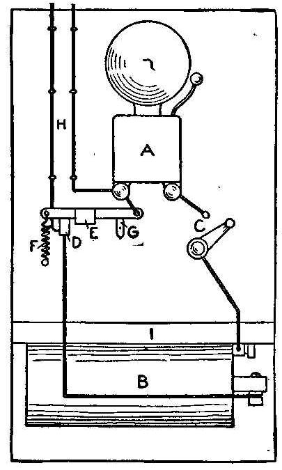
This device consists of a battery and bell connection to an alarm
clock which also acts as a door bell, the whole being mounted on
a board 18 in. long and 12 in. wide.
Referring to the sketch accompanying this article, the letters
indicate as follows: A, bell; B, battery ; C, switch; D, V-shaped
copper strip; E, copper lever with 1-in. flange turned on one
side, whole length, 4 in.; F, spring to throw lever E down in
V-shaped piece to make connection; G, lever to hold out E when
device is used as a door bell; lines H, go, one from bell, A, and
one from battery, B, to the door; I, shelf for clock.
See that the ring in the alarm key of the clock works easily, so
that when it is square across the clock it will drop down. Fasten
a piece of copper about 1 in. long to key, then wind the alarm
just enough so that the key stands straight up and down. Place
the clock on the shelf and the key under the flange of lever E.
Pull lever G down out of the way and close the lever on the
switch. The alarm key will turn and drop down, letting lever E
drop into the V-shaped piece D and make connection.
For the door-bell connection close lever on switch C, and put G
up so that D and E do not come in contact. If anyone is ill and
you do not want the bell to ring, open switch C.
The wiring for this device may all be on the back of the board.
The switch and levers are fastened with small screw bolts, which
allows wiring at the back. Saw two spools in half and fasten the
halves to the four corners of the board at the back, and the
apparatus may be put up where one likes.
To Build a Small Brass Furnace
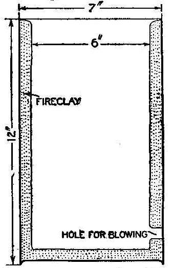
Bend a piece of stout sheet iron 23 in. by 12 in. round so that
the inside diameter is 7 in., and then rivet the seam. Fit in a
round piece of sheet iron for the bottom. Make a hole about the
size of a shilling in the side, 2 in. from the bottom. This is
for blowing.
Line the furnace, bottom and sides with fire-clay to a depth of
1/2 in. Use charcoal to burn and an ordinary bellows for blowing,
says the Model Engineer, London. The best blast is obtained by
holding the nozzle of the bellows about an inch from the hole,
instead of close to it.
Avoid Paper Lamp Shades
Don’t wrap paper around a lamp for a shade. You might go away and
forget it and a fire might be started from the heat. Use a glass
or metal shade. That is what they are for.
Why Gravity Batteries Fail to Work
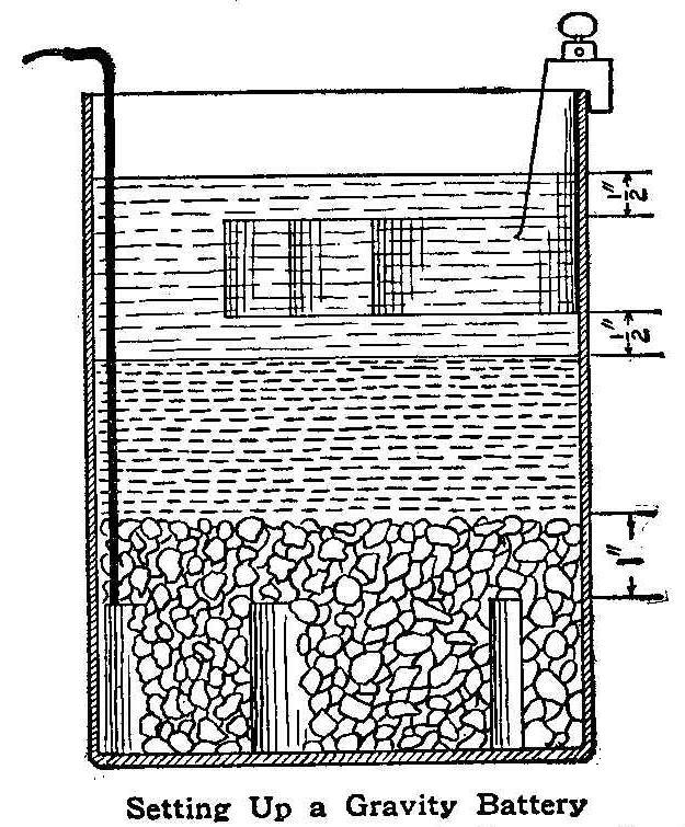
Setting Up a Gravity Battery
Many amateur electricians and some professionals have had
considerable trouble with gravity batteries. They follow
directions carefully and then fail to get good results. The usual
trouble is not with the battery itself, but with the circuit. A
gravity battery is suitable only for a circuit which is normally
closed. It is therefore undesirable for electric bells, induction
coils and all other open-circuit apparatus. The circuit should
also have a high resistance. This makes it impractical for
running fan motors, as the motor would have to be wound with fine
wire and it would then require a large number of batteries to
give a sufficiently high voltage.
To set up a gravity battery: Use about 3-1/2 lb. of blue stone,
or enough to cover the copper element 1 in. Pour in water
sufficient to cover the zinc 1/2 in. Short-circuit for three
hours, and the battery is ready for use. If desired for use
immediately, do not short-circuit, but add 5 or 6 oz. of zinc
sulphate.
Keep the dividing line between the blue and white liquids about
1/2 in. below the bottom of the zinc. If too low, siphon off some
of the white liquid and add the same amount of water, but do not
agitate or mix the two solutions. This type of battery will give
about 0.9 of a volt, and should be used on a circuit of about 100
milli-amperes.
A Skidoo-Skidee Trick

How to Cut the Notches
In a recent issue of Popular Mechanics an article on “The Turning
Card Puzzle” was described and illustrated. Outside of the
scientific side involved, herein I describe a much better trick.
About the time when the expression “skidoo” first began to be
used I Invented the following trick and called it “Skidoo” and
“Skidee,” which created much merriment. Unless the trick is
thoroughly understood, for some it will turn one way, for others
the opposite way, while for others it will not revolve at all.
One person whom I now recall became red in the face by shouting
skidoo and skidee at it, but the thing would not move at all, and
he finally from vexation threw the trick into the fire and a new
one had to be made. Very few can make it turn both ways at will,
and therein is the trick.
Take a piece of hardwood 3/8 in. square and about 9 in. long. On
one of the edges cut a series of notches as indicated in Fig. 1.
Then slightly taper the end marked B until it is nicely rounded
as shown in Fig. 2. Next make an arm of a two-arm windmill such
as boys make. Make a hole through the center of this one arm.
Enlarge the hole slightly, enough to allow a common pin to hold
the arm to the end B and not interfere with the revolving arm.
Two or three of these arms may have to be made before one is
secured that is of the exact proportions to catch the vibrations
right.
To operate the trick, grip the stick firmly in one hand, and with
the forward and backward motion of the other allow the first
finger to slide along the top edge, the second finger along the
side, and the thumb nail will then vibrate along the notches,
thus making the arm revolve in one direction. To make the arm
revolve in the opposite dlrection—keep the hand moving all the
time, so the observer will not detect the change which the hand
makes—allow the first finger to slide along the top, as in the
other movement, the thumb and second finger changing places: e.g.,
In the first movement you scratch the notches with the thumb
nail while the hand is going from the body, and in the second
movement you scratch the notches with the nail of the second
finger when the hand is coming toward the body, thus producing
two different vibrations. In order to make it work perfectly (?)
you must or course say “skidoo” when you begin the first
movement, and then, no matter how fast the little arm is
revolving when changed to the second movement you must say
“skidee” and the arm will immediately stop and begin revolving in
the opposite direction. By using the magic words the little arm
will obey your commands instantly and your audience will be
mystified. If any of your audience presume to dispute, or think
they can do the same let them try it. You will no doubt be
accused of blowing or drawing in your breath, and many other
things in order to make the arm operate. At least it is amusing.
Try it and see.
Contributed by Charles Clement Bradley, Toledo, Ohio.
Effects of Radium
Radium acts upon the chemical constituents of glass, porcelain
and paper, imparting to them a violet tinge; changes white
phosphorus to yellow, oxygen to ozone, affects photograph plates
and produces many other curious chemical changes.
Naval Speed Record
On its official trial trip the British torpedo boat destroyer
“Mohawk” attained the record speed of a little over 39 miles an
hour.
How to Enlarge from Life in the Camera
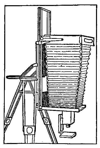
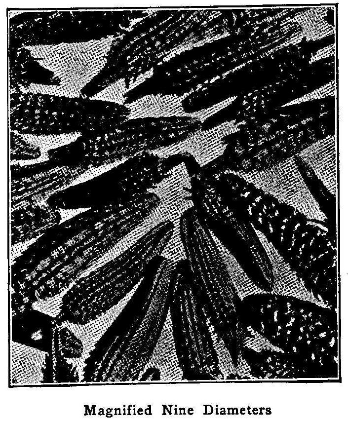
Magnified Nine Diameters
Usually the amateur photographer gets to a point in his work
where the miscellaneous taking of everything in sight is somewhat
unsatisfying: There are many special fields he may enter, and one
of them is photomicrography. It is usually understood that this
branch of photography means an expensive apparatus. If the worker
is not after too high a magnification, however, there is a very
simple and effective means of making photomicrographs which
requires no additional apparatus that cannot be easily and
quickly constructed at home.
Reproduced with this article is a photograph of dandelion seeds—a
magnification of nine diameters or eighty-one times. The
apparatus which produced this photograph consisted of a camera of
fairly long draw, a means for holding it vertical, a short-focus
lens, and, if possible, but not essential, a means for focusing
that lens in a minute manner. On top of the tripod is the folding
arrangement, which is easily constructed at home with two hinged
boards, an old tripod screw, an old bed plate from a camera for
the screw to fit in, and two sliding brass pieces with sets crews
that may be purchased from any hardware store under the name of
desk sliding braces. To the front board is attached a box,
carrying the lens and the bed of the sliding object carrier,
which can be moved forward and back by the rack and pinion, that
also can be obtained from hardware stores. If the bed for the
object carrier be attached to the bed of the camera instead of to
the front board, the object carrier need have no independent
movement of its own, focusing being done by the front and back
focus of the camera; but this is less satisfactory, particularly
when accurate dimensions are to be determined, says the
Photographic Times. This outfit need not be confined to seeds
alone, but small flowers, earth, chemicals, insects, and the
thousand and one little things of daily life—all make beautiful
subjects for enlarged photographs. These cannot be made by taking
an ordinary photograph and enlarging through a lantern. When a
gelatine dry plate is magnified nine diameters, the grains of
silver in the negative will be magnified also and produce a
result that will not stand close examination. Photographs made by
photomicrography can be examined like any other photographs and
show no more texture than will any print.
Steel Pen Used in Draftsman’s Ink Bottle Cork
A steel pen makes an ideal substitute for a quill in the stopper
of the draftsman’s ink bottle. The advantage of this substitute
is that there is always one handy to replace a broken or lost
pen, while it is not so with the quill.
Contributed by George C. Madison, Boston, Mass.
How to Make a Pilot Balloon
By E. Goddard Jorgensen
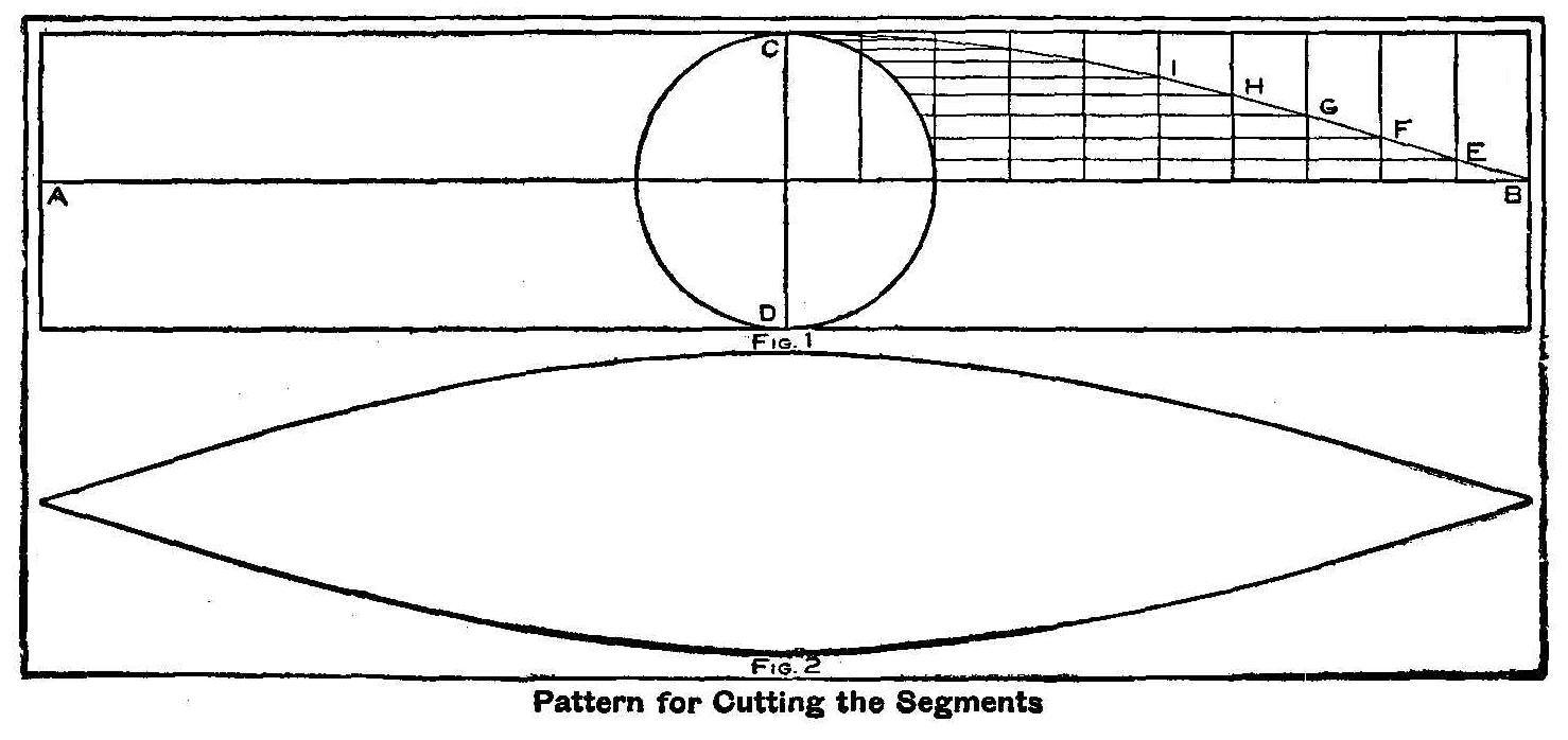
Pattern for Cutting the Segments
Unusual interest is being displayed in ballooning, and as it is
fast becoming the favorite sport many persons would like to know
how to construct a miniature balloon for making experiments. The
following table will give the size, as well as the capacity and
lifting power of pilot balloons:
| Diameter. | Cap. in Cu. Ft. | Lifting Power. |
| 5 ft. | 65 | 4 lb. |
| 6 ft. | 113 | 7 lb. |
| 7 ft. | 179 | 11 lb. |
| 8 ft. | 268 | 17 lb. |
| 9 ft. | 381 | 24 lb. |
| 10 ft | 523 | 33 lb. |
| 11 ft. | 697 | 44 lb. |
| 12 ft. | 905 | 57 lb. |
The material must be cut in suitable shaped gores or segments. In
this article we shall confine ourselves to a 10-ft. balloon. If
the balloon is 10 ft. in diameter, then the circumference will be
approximately 3-1/7 times the diameter, or 31 ft. 5 in. We now
take one-half this length to make the length of the gore, which
is 15 ft. 7-1/2 in. Get a piece of paper 15 ft. 7-1/2 in. long
and 3 ft. wide from which to cut a pattern, Fig. 1. A line, AB,
is drawn lengthwise and exactly in the middle of the paper, and a
line, CD, is drawn at right angles to AB and in the middle of the
paper lengthways. The intersecting point of AB and CD is used for
a center to ascribe a circle whose diameter is the same as the
width of the paper, or 3 ft. Divide one-quarter of the circle
into 10 equal parts and also divide one-half of the line AB in 10
equal parts. Perpendicular lines are drawn parallel with the line
CD intersecting the division points made on the one-half line
AB. Horizontal and parallel lines with AB are drawn intersecting
the division points made on the one-quarter circle and
intersecting the perpendicular line drawn parallel with CD. A
line is now drawn from B to E and from E to F, and so on, until
all the intersecting lines are touched and the point C is
reached. This will form the proper curve to cut the pattern. The
paper is now folded on the line AB and then on the line CD,
keeping the marked part on the outside. The pattern is now cut,
cutting all four quarters at the same time, on the curved line
from B to C. When the paper is unfolded you will have a pattern
as shown in Fig. 2. This pattern is used to mark the cloth, and
after marked is cut the same shape and size.
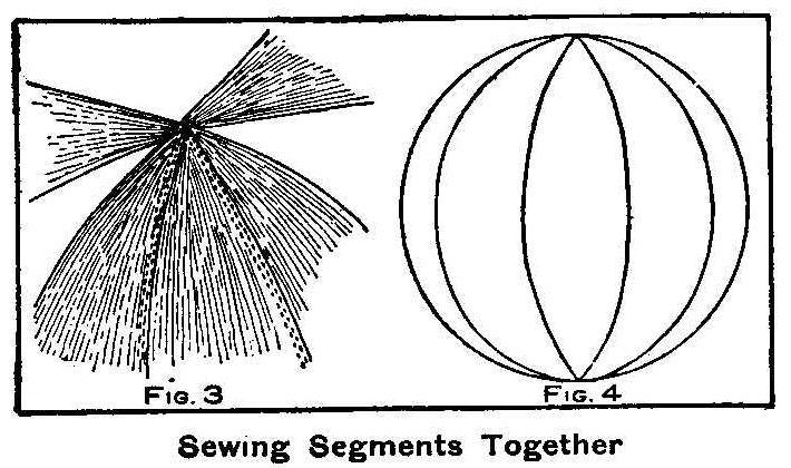
Sewing Segments Together
The cloth segments are sewed together, using a fine needle and
No. 70 thread, making a double seam as shown in Fig. 3. When all
seams are completed you will have a bag the shape shown in Fig.
4. A small portion of one end or a seam must be left open for
inflating. A small tube made from the cloth and sewed into one
end will make a better place for inflating and to tie up tightly.
It is now necessary to varnish the bag in order to make it retain
the gas. Procure 1 gal. of the very best heavy body, boiled
linseed oil and immerse the bag in it. The surplus oil is
squeezed out by running the bag through an ordinary clothes
wringer several times. The bag is now placed in the sun for a
thorough drying. Put the remaining oil in a kettle with 1/8 lb.
of beeswax and boil well together. This solution is afterward
diluted with turpentine so it will work well. When the bag is dry
apply this mixture by rubbing it on the bag with a piece of
flannel. Repeat this operation four times, being sure of a
thorough drying in the sun each time. For indoor coating and
drying use a small amount of
plumbic oxide. This will dry rapidly
in the shade and will not make the oil hard.
Fill the bag with air by using a pair of bellows and leave it
over night. This test will show if the bag is airtight. If it is
not tight then the bag needs another rubbing. The next operation
is to fill the bag with gas.
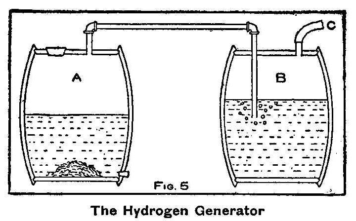
Fig. 5—The Hydrogen Generator
Hydrogen gas is made from iron and
sulphuric acid. The amounts
necessary for a 10-ft. balloon are 125 lb. of iron borings and
125 lb. of sulphuric acid.
1 lb. of iron, 1 lb. of sulphuric acid
and 4 lb. of water will make 4 cu. ft. of gas in one hour. Secure
two empty barrels of about 52 gal. capacity and connect them, as
shown in Fig. 5, with 3/4-in. pipe. In the barrel, A, place the
iron borings and fill one-half full of clear water. Fill the
other barrel, B, with water 2 in. above the level of the water in
barrel A. This is to give a water pressure head against foaming
when the generator is in action. About 15 lb. of lime should be
well mixed with the water in the barrel B. All joints must be
sealed with plaster of Paris. Pour in one-half of the acid into
the barrel, A, with the iron borings. The barrels are kept tight
while the generation is going on with the exception of the
outlet, C, to the bag. When the action is stopped in the
generator barrel, A, let the solution run out and fill again as
before with water and acid on the iron borings. The outlet, C,
should be always connected with the bag while the generator is in
action. The 3/4-in. pipe extending down into the cooling tank,
B, should not enter into the water over 8 in. When filled with
gas the balloon is ready for a flight at the will of the
operator.
How to Clean a Clock
It is very simple to clean a clock, which may sound rather
absurd. For an amateur it is not always necessary to take the
clock to pieces. With a little care and patience and using some
benzine, a clean white rag, a sable brush and some oil a clock
can be cleaned and put into first-class running order. The
benzine should be clean and free from oil. You can test benzine
by putting a little on the back of the hand; if it is good it
will dry off, leaving the hand quite clean, but if any grease
remains on the hand, it is not fit to use.
The oil should be of the very best that can be procured.
Vegetable oils should never be used. Clock oil can be procured
from your druggist or jeweler. All loose dirt should be removed
from the works by blowing with bellows, or a fan, or dusting with
a dry brush; in the latter case great care should be exercised
not to injure any of the parts. Dip the brush in the benzine and
clean the spindles and spindle holes, and the teeth of the
escapement wheel. After washing a part, wipe the brush on the rag
and rinse in the benzine; this should be repeated frequently,
until no more dirt is seen.
When the clock has dried, oil the spindle holes carefully; this
may be done with a toothpick or a sliver of woodcut to a fine
point. Oil the tooth of the escapement wheel slightly, using a
fine brush.
How to Make Blueprint Lantern Slides
Lantern slides of a blue tone that is a pleasing variety from the
usual black may be made from spoiled or old plates which have not
been developed, by fixing, washing well and then dipping five
minutes in the following solution:
| Solution A. | |
| Green Iron ammonium citrate | 150 gr. |
| Water | 1 oz. |
| Solution B. | |
| Potassium ferrocyanide | 50 gr. |
| Water | 1 oz. |
Prepare the solutions separately and mix equal parts for use, at
the time of employment. Dry the plates in the dark, and keep in
the dark until used. Printing is done in the sun, and a vigorous
negative must be used, says the Moving Picture World. Exposure,
20 to 30 minutes. Wash 10 minutes in running water and dry. Brown
or purple tones may be had by sensitizing with the following
solution instead of the above:
| Distilled water | 1 oz. |
| Sliver nitrate | 50 gr. |
| Tartaric or citric acid | 1/2 oz. |
Bathe the plates 5 minutes, keeping the fingers out of the
solution, to avoid blackened skin. Dry in the dark. Print to
bronzing under a strong negative; fix in hypo, toning first if
desired.
A Substitute for a Ray Filter
Not many amateur photographers possess a ray filter. A good
substitute is to use the orange glass from the ruby lamp. This
can be held in position in front of the lens with a rubber band.
A longer exposure will be necessary, but good cloud effects can
be procured in this manner.
Electric Lamp Experiments
Incandescent electric lamps can be made to glow so that they may
be seen in a dark room by rubbing the globe on clothing or with a
paper, leather or tinfoil and immediately holding near a 1/2-in.
Ruhmkorff coil which is in action but not sparking. The miniature
16 cp., 20 and 22-volt lamps will show quite brilliantly, but the
110-volt globes will not glow. When experimenting with these
globes everything should be dry. A cold, dry atmosphere will give
best results.
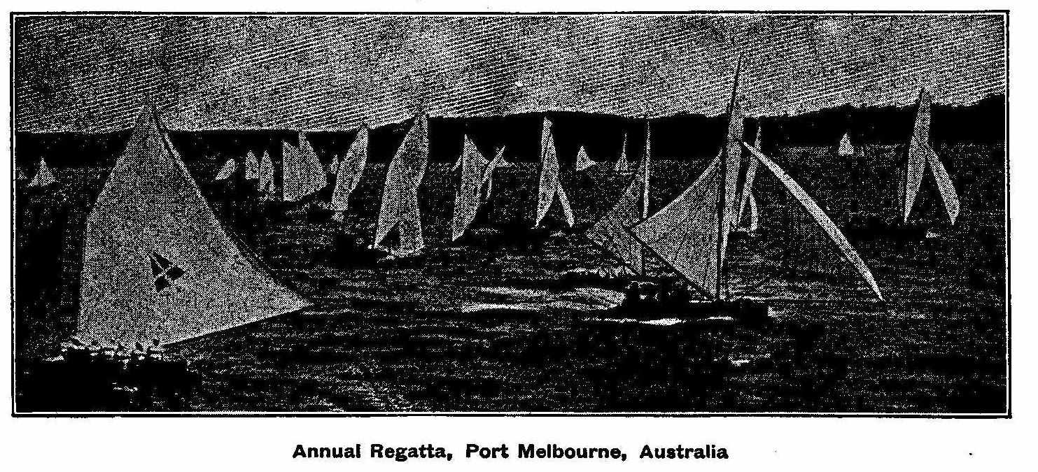
Annual Regatta, Port Melbourne, Australia
How to Make a Simple Wireless Telegraph
By Arthur E. Joerin
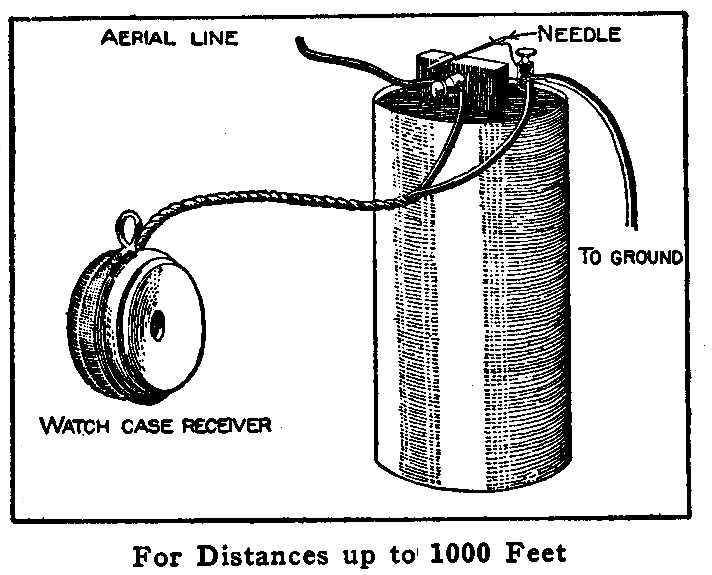
For Distances up to 1000 Feet
An efficient wireless-telegraph receiving apparatus for distances
up to 1,000 ft. may be constructed in the following manner:
Attach a watchcase telephone receiver to a dry cell, or battery,
of any make. The negative pole, or zinc, of the cell is connected
to a ground wire. This is done by attaching to a gas or water
pipe. The positive pole, or carbon, of the cell is connected to
the aerial line. This aerial collector can be made in various
ways, either by using a screen wire or numerous wires made in an
open coil and hung in the air. File a V-shaped groove in the
upper end of the carbon of the cell. Attach a small bent copper
wire in the binding post that is attached to the zinc of the
cell. In the bend of this wire and the V-shaped groove filed into
the carbon, lay a needle. This will complete the receiving
station. Use a spark coil in connection with a telegraph key for
the sending station, making a ground with one wire, and have the
other connected with another aerial line.
By connecting the telephone receiver to the cell and at the same
time having a short circuit a receiving station is made. As the
telephone offers a high resistance, part of the current will try
to take the shorter high resistance through the needle. If the
waves strike across the needle, the resistance is less, and thus
less current travels through the telephone receiver. If the wave
ceases, the resistance between the needle and the carbon is
increased, and as less current will flow the short way, it is
compelled to take the longer metallic way through the windings of
the receiver, which will cause the clickings that can be heard.
To Preserve Putty
Putty, when left exposed to the air, will soon become dry and
useless. I have kept putty in good condition for more than a year
by placing it in a glass jar and keeping it entirely covered with
water.
How to Make a Small Storage Battery
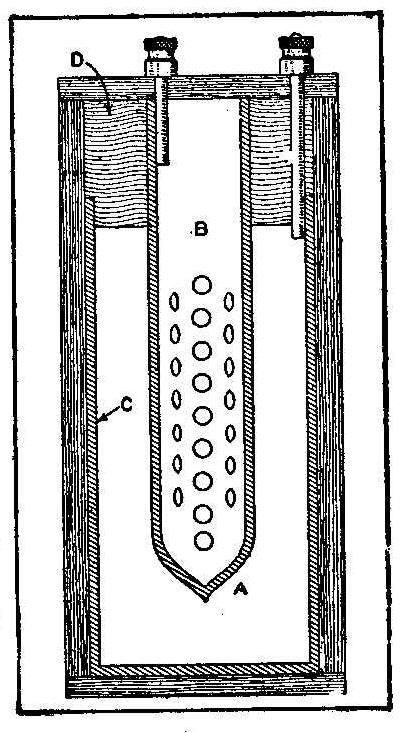
The cell of a storage battery consists of two plates, a positive
and a negative, made of lead
and placed in a dilute solution of
sulphuric acid. Large batteries made of large cells have a great
number of plates, both positive and negative, of which all
positive plates are connected to one terminal and the negative
plates to the other terminal. The storage cell, as described
below, is the right size to be charged by a few gravity cells and
is easily made.
Secure a piece of 1-3/4-in. lead pipe,
5 in. long, and cut both
ends smooth and square with the pipe. Solder a circular disk of
lead to one end, forming a cup of
the pipe. As this cup must hold
the sulphuric acid it must be perfectly liquid-tight.
It is also necessary to get another
lead pipe of the same length
but only 3/4 in. in diameter. In this pipe should be bored as
many 1/8 in. holes as possible, except for about 1 in. on each
end. One end of this tube is hammered together as shown at A in
the sketch to make a pocket to hold the paste. This, of course,
does not need to be watertight.
A box of wood is made to hold the larger tube or cup. This box
can be square, and the corners left open around the cup can be
filled with sawdust. A support is now made from a block of wood
to hold the tube, B, in place and to keep it from touching the
cup C. This support or block, D, is cut circular with the same
diameter as the lead cup C.
The lower portion of the block is cut
away so it will just fit inside of the cup to form a stopper. The
center of this block is now bored to make a hole the same size as
the smaller lead pipe.
Place the lead pipe in the hole and
immerse it in smoking hot paraffine wax, and leave it until the
wood has become thoroughly saturated with the hot wax. Use care
to keep the wax from running on the lead at any place other than
the end within the wood block. Two binding-posts should be
attached, one to the positive, or tube B, and the other to the
negative, or tube C, by soldering the joint.
A paste for the positive plate is made from 1 part sulphuric acid
and 1 part water with a sufficient amount of red
lead added to
make of thick dry consistency. When mixing the acid and water, be
sure to add the acid to the water and not the water to the acid.
Also remember that sulphuric acid
will destroy anything that it
comes in contact with and will make a painful burn if it touches
the hands. Stir the mixture with a stick and when a good dry
paste is formed, put it into the smaller tube and ram it down
until the tube is almost filled. The paste that may have come
through the holes is scraped off and the tube set aside to dry.
The large tube or cup is filled with a diluted solution of
sulphuric acid.
This solution should be about one-twelfth acid.
The cell is now complete and ready for storing the current. The
cell may be charged with three gravity cells. These are connected
in series and the positive terminal binding-post on the storage
cell is connected to the wire leading from the copper plate in
the gravity cell. The other plate is connected to the zinc. The
first charge should be run into the cell for about one week and
all subsequent charges should only take from 10 to 12 hours.
Fitting a Plug in Different Shaped Holes
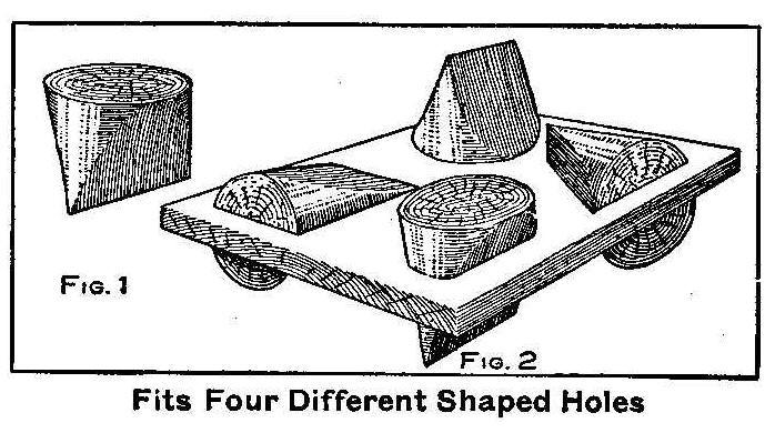
Fits Four Different Shaped Holes
A certain king offered to give the prince his liberty if he could
whittle a plug that would fit four different shaped holes,
namely: a square hole, a round one, an oblong one and a
triangular one, says the Pathfinder. A broomstick was used to
make the plug and it was whittled in the shape shown in Fig. 1.
The holes in the different places as shown in Fig. 2, were fitted
by this one plug.
How to Make a Lightning Arrester
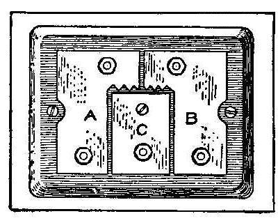
Secure a piece of wood about 3-1/2 in. square that will furnish a
nice finish and round the corners and make a small rounding edge
as shown in the sketch. From a piece of brass 1/16 in. thick cut
two pieces alike, A and B, and match them together, leaving about
1/16 in. between their upper edges and fasten them to the wood
with binding-posts. The third piece of brass, C, is fitted
between the pieces A and B allowing a space of 1/16-in. all
around the edge. One binding-post and a small screw will hold
the piece of brass, C, in place on the wood. The connections are
made from the line wires to the two upper binding-posts and
parallel from the lower binding-posts to the instrument. The
third binding-post on C is connected to the ground wire. Any
heavy charge from lightning will jump the saw teeth part of the
brass and is grounded without doing harm to the instruments used.
Contributed by Edwin Walker, Chicago, Ill.
A Home-Made Punt
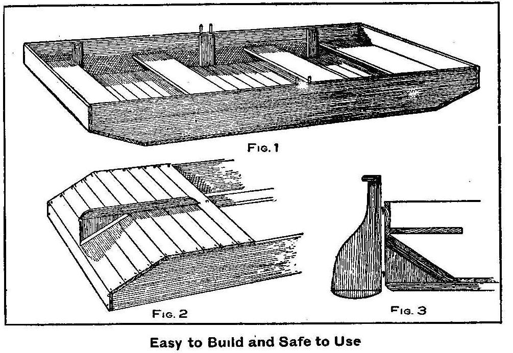
Easy to Build and Safe to Use
A flat bottom boat is easy to make and is one of the safest
boats, as it is not readily overturned. It has the advantage of
being rowed from either end, and has plenty of good seating
capacity.
This punt, as shown in Fig. 1, is built 15 ft. long, about 20 in.
deep and 4 ft. wide. The ends are cut sloping for about 20 in.
back and under. The sides are each made up from boards held
together with battens on the inside of the boat near the ends and
in the middle. One wide board should be used for the bottom
piece. Two pins are driven in the top board of each side to serve
as oarlocks.
The bottom is covered with matched boards not over 5 in. wide.
These pieces are placed together as closely as possible, using
white lead
between the joints and nailing them to the edges of
the side boards and to a keel strip that runs the length of the
punt, as shown in Fig. 2. Before nailing the boards place lamp
wicking between them and the edges of the side boards. Only
galvanized nails should be used. In order to make the punt
perfectly watertight it is best to use the driest lumber
obtainable. At one end of the punt a skag and a rudder can be
attached as shown in Fig. 3.
Photographers’ Printing Frame Stand
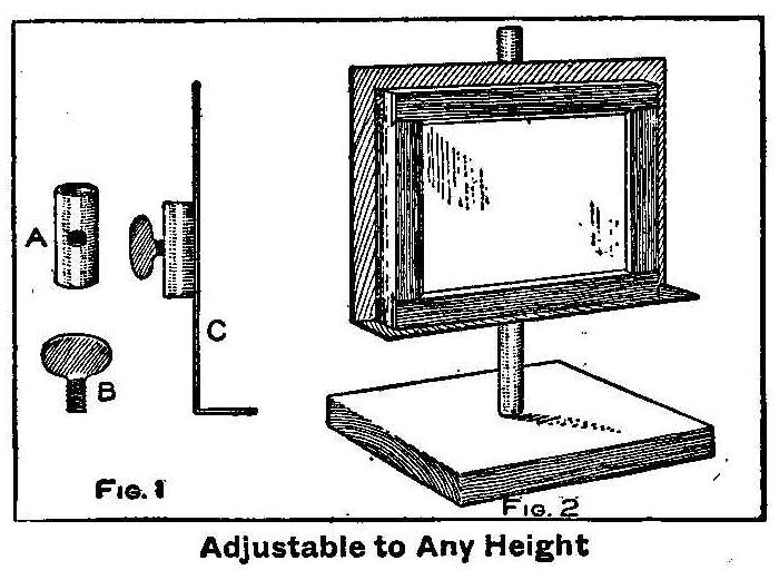
Adjustable to Any Height
When using developing papers it is always bothersome to build up
books or small boxes to make a place to set the printing frame in
front of the light. Details for making a small stand that is
adjustable to any desired height are shown in the sketch. In Fig.
1 is shown the construction of the sliding holder. A piece of
1/4-in. gas pipe, A, is cut 1 in. long and fitted with a
thumbscrew, B. The piece of pipe is soldered to the middle on the
back side of a piece of metal that is about 4 by 4-1/2 in. with
its lower edge turned up to form a small shelf as shown at C. The
main part of the stand is made by inserting a 5/16-in. rod
tightly into a block of hard maple wood that is 1 in. thick and
3-1/2 in. square (Fig 2). The pipe that is soldered to the metal
support will slide up and down the rod and the thumbscrew can be
set to hold it at the desired point.
Heat and Expansion
Take an electric light bulb from which the air has not been
exhausted and immerse it in water and then break off the point.
As there is a vacuum in the bulb it will quickly fill with water.
Shake the bulb gently until a part of the water is out and then
screw the bulb into a socket with the point always downward.
Apply the current and the heated air inside will soon expand and
force the water out with great rapidity. Sometimes this
experiment can be done several times by using the same bulb.
Contributed by Curtiss Hill, Tacoma, Wash.
Photographing a Streak of Lightning
The accompanying illustration is a remarkable photograph of a
streak of lightning. Many interesting pictures of this kind can
be made during a storm at night. The camera is set in a place
where it will not get wet and left standing with the shutter open
and the plate ready for the exposure. Should a lightning streak
appear within the range of the lens it will be made on the plate,
which can be developed in the usual manner. It will require some
attention to that part of the sky within the range of the lens so
as to not make a double exposure by letting a second flash enter
the open lens.
Contributed by Charles H. Wagner.
How to Make a Small Single-Phase Induction Motor
By C. H. Bell
The following notes on a small single-phase induction motor,
without auxiliary phase, which the writer has made, may be of
interest to some of our readers, says the Model Engineer. The
problem to be solved was the construction of a motor large enough
to drive a sewing machine or very light lathe, to be supplied
with 110-volt alternating current from a lighting circuit, and to
consume, if possible, no more current than a 16-cp. lamp. In
designing, it had to be borne in mind that, with the exception of
insulated wire, no special materials could be obtained.
The principle of an induction motor is quite different from that
of the commutator motor. The winding of the armature, or “rotor,”
has no connection with the outside circuit, but the current is
induced in it by the action of the alternating current supplied
to the winding of the field-magnet, or “stator.” Neither
commutator nor slip rings are required, and all sparking is
avoided. Unfortunately, this little machine is not self-starting,
but a slight pull on the belt just as the current is turned on is
all that is needed, and the motor rapidly gathers speed provided
no load is put on until it is in step with the alternations of
the supply. It then runs at constant speed whether given much or
little current, but stops if overloaded for more than a few
seconds.
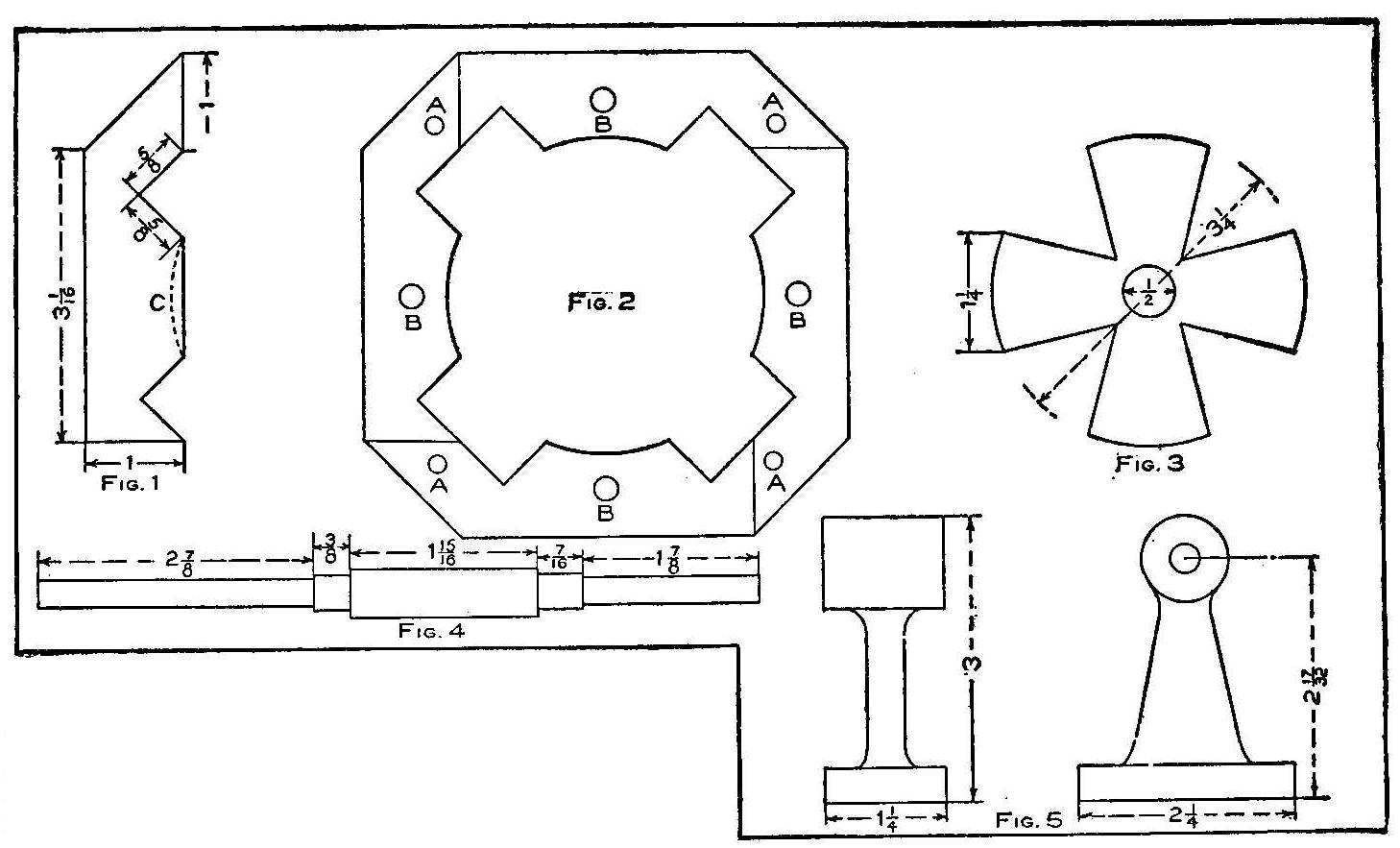
The stator has four poles and is built up of pieces of sheet iron
used for stove pipes, which runs about 35 sheets to the inch. All
the pieces are alike and cut on the lines with the dimensions as
shown in Fig. 1, with the dotted line, C, to be filed out after
they are placed together. Each layer of four is placed with the
pointed ends of the pieces alternately to the right and left so
as to break joints as shown in Fig. 2. The laminations were
carefully built up on a board into which heavy wires had been
driven to keep them in place until all were in position and the
whole could be clamped down. In the middle of the pieces 1/4-in.
holes, B, were then drilled and 1/4-in. bolts put in and
tightened up, large holes being cut through the wood to enable
this to be done. The armature tunnel was then carefully filed out
and all taken apart again so that the rough edges could be
scraped off and the laminations given a thin coat of shellac
varnish on one side. After assembling a second time, the bolts
were coated with shellac and put into place for good. Holes 5-32
in. in diameter were drilled in the corners, A, and filled with
rivets, also varnished before they were put in. When put together
they should make a piece 2 in. thick.
This peculiar construction was adopted because proper stampings
were not available, and as every bit of sheet iron had to be cut
with a small pair of tinners’ snips, it was important to have a
very simple outline for the pieces. They are not particularly
accurate as it is, and when some of them got out of their proper
order while being varnished, an awkward job occurred in the
magnet which was never entirely corrected. No doubt some energy
is lost through the large number of joints, all representing
breaks in the magnetic circuit, but as the laminations are
tightly held together and the circuit is about as compact as it
could possibly be, probably the loss is not as great as it would
appear at first sight.
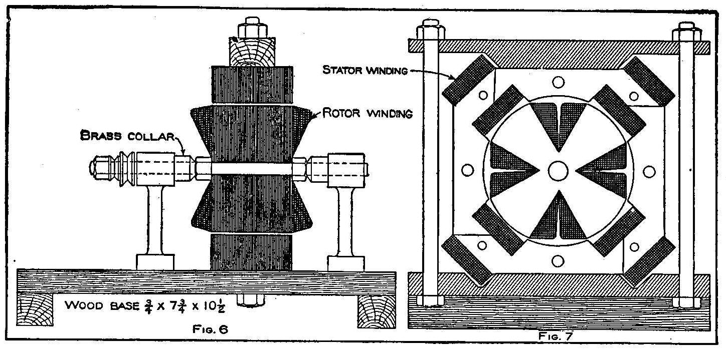
The rotor is made of laminations cut from sheet iron, as shown in
Fig. 3, which were varnished lightly on one side and clamped on
the shaft between two nuts in the usual way. A very slight cut
was taken in the lathe afterwards to true the circumference. The
shaft was turned from 1/2-in. wrought iron, no steel being
obtainable, and is shown with dimensions in Fig. 4. The bearings
were cast of babbitt metal, as shown in Fig. 5, in a wooden mold
and bored to size with a twist drill in the lathe. They are
fitted with ordinary wick lubricators. Figures 6 and 7 are
sections showing the general arrangement of the machine.
The stator is wound full with No. 22 double cotton-covered copper
wire, about 2-1/2 lb. being used, and the connections are such as
to produce alternate poles—that is, the end of the first coil is
joined to the end of the second the beginning of the second to
the beginning of the third, and the end of the third to the end
of the fourth, while the beginnings of the first and fourth coils
connect to the supply.
The rotor is wound with No. 24 double cotton-covered copper wire,
each limb being filled with about 200 turns, and all wound in the
same direction. The four commencing ends are connected together
on one side of the rotor and the four finishing ends are soldered
together on the other. All winding spaces are carefully covered
with two layers of cambric soaked in shellac, and as each layer
of wire was wound, it was well saturated with varnish before the
next was put on.
This type of motor has drawbacks, as before stated, but if
regular stampings are used for the laminations, it would be very
simple to build, having no commutator or brushes, and would not
easily get out of order. No starting resistance is needed, and as
the motor runs at constant speed, depending upon the number of
alterations of the supply, a regulating resistance is not needed.
Carbolic Acid Burns
The pain of carbolic acid burns can be relieved promptly by
washing with alcohol, if applied immediately. If too late for
alcohol to be of use, brush with water containing saturated
solution of picric acid.
How to Make a Paper Book Cover
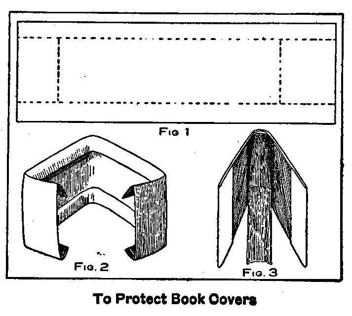
To Protect Book Covers
Book covers become soiled in handling and especially school
books. Various methods are applied for making a temporary cover
that will protect the book cover. A paper cover can be quickly
made by using a piece of paper larger than both covers on the
book when they are open. Fold the paper on the long dotted line,
as shown in Fig. 1. When the folds are made the paper should then
be just as wide as the book cover is high. The ends are then
folded on the short dotted lines, which will make it appear as
shown in Fig. 2. The paper thus folded is placed on the book
cover as shown in Fig. 3.
Contributed by C. E. McKinney, Jr., Newark, N. J.
How to Make Lantern Slides
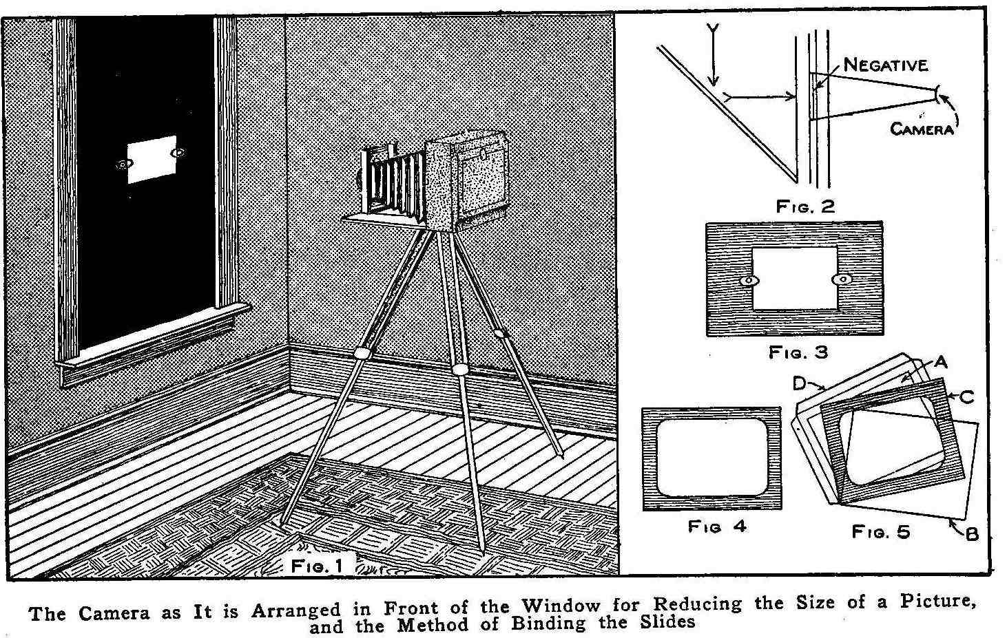
The Camera as It is Arranged in Front of the Window for Reducing
the Size of a Picture, and the Method of Binding the Slides
The popularity of lantern slides, and especially of colored ones,
as a means of illustrating songs, has caused so large a demand
for this class of work that almost any amateur may take up slide
making at a good profit. The lantern slide is a glass plate,
coated with slow and extremely fine-grained emulsion. The size is
3-1/4 by 4 in. A lantern slide is merely a print on a glass plate
instead of on paper. Lantern slides can be made in two different
ways. One is by contact, exactly the same as a print is made on
paper, and the other by reduction in the camera. In making slides
by contact, select the negative and place it in the printing
frame and put the lantern plate upon it, film to film. Clamp down
the back and expose just as in making a print. A good method of
exposing is to hold a lighted match about 3 in. from the frame
for three or more seconds according to the density.
Development is carried on in the same manner as with a negative.
The image should appear in. about a minute, and development
should be over in three or four minutes. If the exposure has been
correct, the high lights will stay white throughout the
development and will come out as clear glass after fixing. It is
best to use the developers recommended by the manufacturer of the
plates used, the formulas being found in each package of plates.
It is best, also, to use a plain fixing bath, which must be fresh
and kept as cool as possible in hot weather.
The lantern-slide film that is new on the market can be handled
in the same manner as the glass-plate slide, except that the
binding is different. The results are the same and the slides are
not so bulky to handle. Being unbreakable, they are much used by
travelers. The manner of binding them for use in a lantern is
described on the circular enclosed with the film.
When the negative is larger than the lantern-slide plate, and it
is desirable to reduce the entire view upon the slide, a little
extra work will be necessary. Select a room with one window, if
possible, and fit a light-proof frame into it to keep out all
light with the exception of a hole in which to place the
negative, as shown in Fig. 1. Unless this hole is on a line with
the sky it will be necessary to place a sheet of white cardboard
at an angle of 45 deg. on the outside of the frame to reflect the
light through the negative as shown in Fig. 2. Make or secure an
inside kit to place in the plate holder of your camera to hold
the lantern slide plate as shown in Fig. 3. Draw lines with a
pencil, outlining on the ground glass of the camera the size of
the lantern slide plate, and in the place where the plate will be
in the plate holder when placed in position in the camera. This
will enable you to focus to the proper size. Place the camera in
front of the hole in the frame, place the negative in the hole
and focus the camera for the lantern slide size. Expose with a
medium stop for about 20 seconds and treat the plate the same as
with the contact exposure.
When dry the lantern slide plate may be tinted any color by means
of liquid colors. These can be purchased from any photo material
store. In coloring the slide plate it is only necessary to
moisten the gelatine film from time to time with a piece of cloth
dampened in water. The colors may then be spread evenly with a
soft brush, which should be kept in motion to prevent spots. The
slide is put together by placing a mat made of black paper, as
shown in Fig. 4, on the gelatine side of the lantern slide, A,
Fig. 5, and then a plain glass, B, over the mat, C, and the three
bound together with passe-partout tape, D. Contrasty negatives
make the best slides, but the lantern slide plate should be made
without any attempt to gain density.
How To Make A Porch Swing Chair
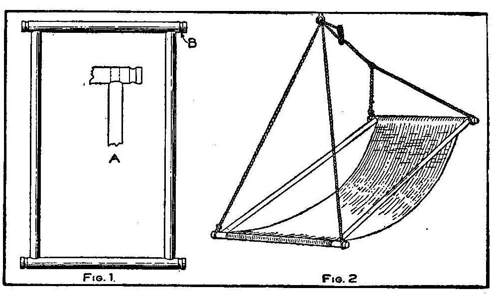
The material needed for making this porch swing chair are two
pieces of round wood 2-1/2 in. in diameter and 20 in. long, and
two pieces 1-1/4 in. in diameter and 40 in. long. These longer
pieces can be made square, but for appearance it is best to have
them round or square with the corners rounded. A piece of canvas,
or other stout cloth, 16 in. wide and 50 in. long, is to be used
for the seat. The two short pieces of wood are used for the ends
of the chair and two 1-in. holes are bored in each end of them
1-1/2 in. from the ends, and between the holes and the ends
grooves are cut around them to make a place to fasten ropes, as
shown at B, Fig. 1. The two longer pieces are used for the sides
and a tenon is cut on each end of them to fit in the 1-in. holes
bored in the end pieces, as shown at A, Fig. 1. The canvas is now
tacked on the end pieces and the pieces given one turn before
placing the mortising together.
The chair is now hung up to the porch ceiling with ropes attached
to a large screw eye or hook. The end of the chair to be used for
the lower part is held about 16 in. from the floor with ropes
direct from the grooves in the end pieces to the hook. The upper
end is supported by using a rope in the form of a loop or bail,
as shown in Fig. 2. The middle of the loop or bail should be
about 15 in. from the end piece of the chair. Another rope is
attached to the loop and through the hook and to a slide as
shown. This will allow for adjustment to make the device into a
chair or a hammock.
Contributed by Earl R. Hastings, Corinth, Vt.
How to Find the Blind Spot in the Eye
Make a small black circular dot 1/2 in. in diameter on a piece of
cardboard and about 3 in. from the center of this dot draw a
star. Hold the cardboard so that the star will be directly in
front of one eye, while the dot will be in front of the other. If
the star is in front of the left eye, close the right eye and
look steadily at the star while you move the cardboard until the
point is reached where the dot disappears. This will prove the
presence of a blind spot in a person’s eye. The other eye can be
given the same experiment by turning the cardboard end for end.
The blind spot does not indicate diseased eyes, but it simply
marks the point where the optic nerve enters the eyeball, which
point is not provided with the necessary visual end organs of the
sight, known as rods and cones.
Beeswax Substitute
A wax from the rafie palm of Madagascar is being used as a
substitute for beeswax.
Home-Made Water Wheel Does Family Washing
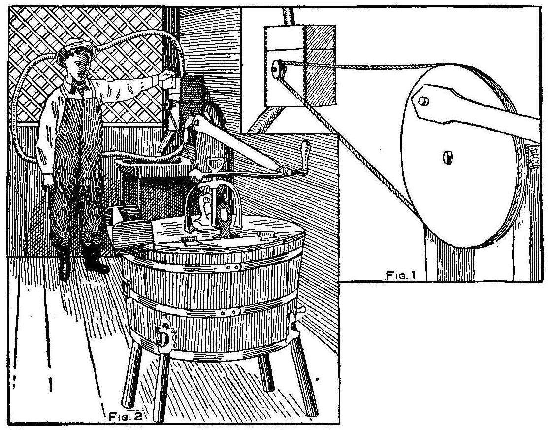
The accompanying sketch illustrates a very ingenious device which
does the family washing, as well as to operate other household
machines. A disk 1 in. in thickness and 10 in. in diameter was
cut from a piece of rough board, and on its circumference were
nailed a number of cup-shaped pieces cut from old tin cans. A
hole was then bored through the center of the disk and an old
piece of iron rod was driven through to form a shaft. Two holes
were then bored opposite each other through the sides of a wooden
box in which the disk was placed, allowing the shaft to project
through the holes. A small grooved wooden pulley was driven
tightly on one of the projecting ends of the shaft. The top of
the box was then tightly closed and a hole, large enough to admit
the nozzle of a garden hose, was bored so that the jet of water
would flow upon the tin buckets that were nailed to the
circumference of the wheel or disk. Another hole was bored in the
bottom of the box large enough to allow the waste water to run
away freely. A belt, made from an ordinary sash cord, was run
from the small pulley on the waterwheel to a large pulley, as
shown in Fig. 1. A pitman was attached to the large pulley, which
operates the washing machine by its reciprocating motion, and the
length of the stroke is adjusted by moving the position of the
hinge joint on the arm of the washing machine, as shown in Fig.
2. The pressure at the nozzle is about 20 lb. per square inch,
and is sufficient to drive the waterwheel under all ordinary
circumstances.
Contributed by P. J. O’Gara, Auburn, Cal,
An Optical Illusion
When looking at the accompanying sketch you will say that the
letters are alternately inclined to the right and left. They are
not so and can be proved by measuring the distance of the top and
bottom of any vertical strokes from the edge of the entire block.
They will be found to be exactly the same distance. Or take any
of the horizontal strokes of the four letters and see how far
their extremities are from the top and bottom of the entire
block. It will be found that a line joining the extremities of
the strokes are strictly parallel to the top or bottom and that
they are not on a slant at all. It is the slant of the numerous
short lines that go to make up the letter as a whole that
deceives the eye.
Home-Made Micrometer
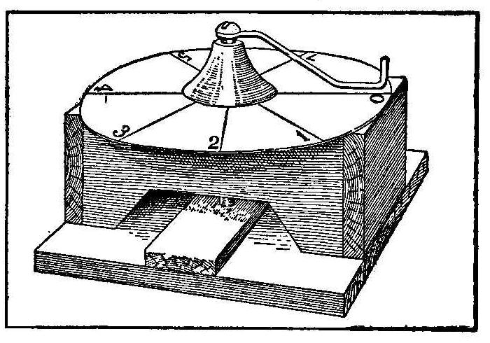
It often becomes necessary to find the thickness of material so
thin, or inconvenient to measure, that a rule or other measuring
device will not serve the purpose. A simple, fairly accurate, and
easily made apparatus of the micrometer form may be constructed
as shown by the accompanying sketch. Secure a common iron or
brass bolt about 1/4-in. in diameter and about 2-1/2 in. long,
with as fine a thread as possible, and the thread cut to within a
short distance of the head of the bolt. The head of the bolts
should have a slot cut for the use of a screwdriver. Clamp
together two blocks of wood with square corners which are about 1
in. wide, 3/4 in. thick and 2-1/2 in. long and fasten them
together with small pieces nailed across the ends. The width of
the blocks will then be about 2 in. Bore a 1/4-in. hole through
the center of the blocks in the 2 in. direction. Remove the clamp
and set the nut into one of the blocks, so that the hole will be
continuous with the hole in the wood. Cut out a piece from the
block combination, leaving it shaped like a bench, and glue the
bottoms of the legs to a piece of thin board about 2-1/2 in.
square for a support.
Solder one end of a stiff wire that is about 2 in. long to the
head of the bolt at right angles to the shaft, and fix a disc of
heavy pasteboard with a radius equal to the length of the wire,
and with its circumference graduated into equal spaces, to serve
in measuring revolutions of the end of the wire, to the top of
the bench. Put the bolt in the hole, screwing it through the nut,
and the construction is complete. The base is improved for the
measuring work by fastening a small piece of wood on the board
between the legs of the bench. A small piece of metal is glued on
this piece of wood at the point where the bolt meets it.
Find the number of threads of the screw to the inch by placing
the bolt on a measuring rule, and counting the threads in an inch
of its length. The bolt in making one revolution will descend a
distance equal to the distance between the threads.
The device is used by placing the object whose thickness is to be
measured on the base under the bolt, and screwing the bolt down
until its end just touches the object, then removing the object,
and screwing the bolt down until its end just touches the base,
carefully noting while doing so the distance that the end of the
wire moves over the scale. The part of a rotation of the bolt, or
the number of rotations with any additional parts of a rotation
added, divided by the number of threads to the inch, will be the
thickness of the object. Quite accurate measurements may be made
with this instrument, says the Scientific American, and in the
absence of the expensive micrometer, it serves a very useful
purpose.
Another Electric Lamp Experiment
Break a portion of the end off from a 16-cp. globe that has been
thrown away as useless. Shake the globe until all the filament
is broken away, leaving only the ends of the platinum wire
exposed. Screw the globe into a socket that sets upright and fill
it with salt water. Make one connection to the socket from the
positive wire of a 110 volt circuit and the other to a ground.
When the current is turned on small stars will be seen in the
globe, which show up fine at night.
Contributed by Lindsay McMillan, Santa Maria, Oal.
Removing Ink Stains
Two or three applications of milk which are wiped up with a dry
cloth will remove india ink spots on carpets.
Feat of Balancing on Chairs
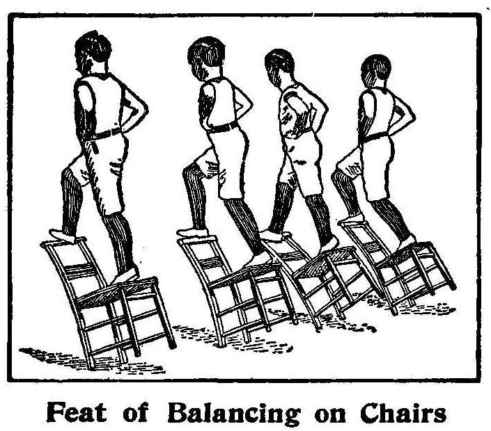
Among the numerous physical exercises is the feat of balancing on
the two rear legs of a chair while one foot rests on the front
part of the seat and the other on the back of the chair. This
may appear to be a hard thing to do, yet with a little practice
it may be accomplished. This exercise is one of many practiced by
the boys of a boys’ home for an annual display given by them. A
dozen of the boys will mount chairs at the same time and keep
them in balance at the word of a commanding officer.
How to Make a Merry-Go-Round Swing
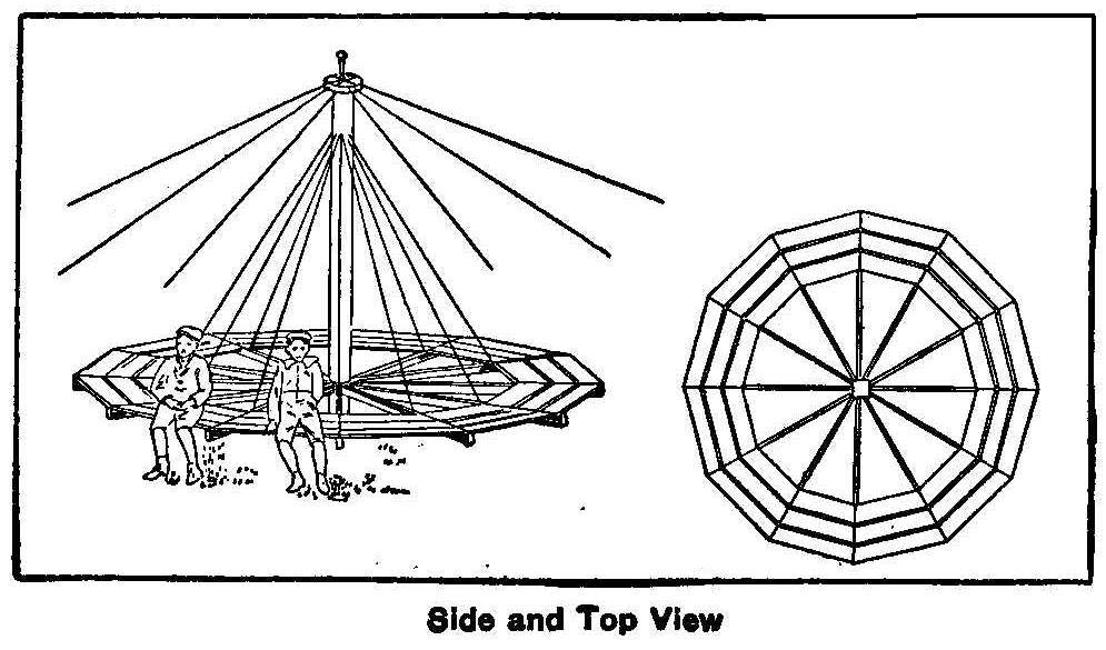
Side and Top View
A 6 by 6-in. piece of wood 12 ft. long is used for the center
pole. Bore a 3/4-in. hole in each end to a depth of 6 in. Place a
3/4-in. bolt in each hole, the bolt being long enough to protrude
2 in. beyond the end of the wood. Short pieces of wood are nailed
on the center pole about 2 ft. from the end that is to be used
for the bottom. This should form a hub on which to place the
inner ends of the extending spokes that hold the platform. The
spokes are made from twelve pieces of 2 by 4-in. material 12 ft.
long.
Usually a wheel can be found in a scrap pile suitable to place on
the pin that is in the top end of the center pole. The wheel
should be open or have spokes. This wheel is used to attach wires
for guying. The bottom pin in the center pole is placed in a hole
that is bored into a block of wood about 12-in. square and 3 or 4
in. thick. A piece of sheet metal should be drilled and placed on
the pin between the block and end of the pole to make a smooth
bearing. The center pole is now placed in position and guyed with
six wires that are about 35 ft. long. Stakes are driven into the
ground and the wires fastened to them and to the wheel at the top
end of the pole. Care should be taken when attaching the wires to
get the center pole to stand perpendicular. Twelve hooks should
be placed at equal distances around the center pole about 1 ft.
from the top end. Wires are fastened to these hooks and to the
twelve 2 by 4-in. pieces used for the spokes. The wires should be
tied around each spoke about 2 ft. from the ends. Space the
spokes with equal divisions and cover the outer 2 ft. of the ends
with boards, as shown in the plan sketch on the right hand end of
the drawing. The boards may be nailed or bolted. If bolted and
the wires made in a loop at the hooks, the swing can easily be
taken apart and changed from one place to another.
Contributed by A. O. Graham, Fort Worth, Tex.
Home-Made Arc Lamp
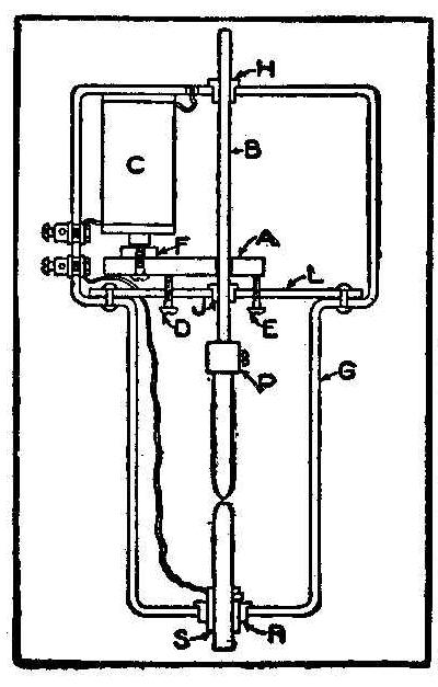
The frame of the lamp is made from bar metal 3/4 in. wide and 1/8
in. thick, bent and welded to make a continuous loop in the shape
as shown at G in the sketch. This frame should be about 10-1/2
in. long with the upper or wider part 4 in. long, and the lower
part 6-1/2 in. long. The width should be about 5-1/4 in. at the
top and 4 in. at the bottom. A cross bar, L, made of the same
material, is fitted into the off-set in the frame and riveted.
Holes are drilled through the frame and brass bushings, H and J,
are fitted for bearings to receive the adjusting brass rod, B,
which should be 1/4 in. in diameter. A brass curtain rod can be
used for the rod B, and on its lower end a socket, P, is
soldered.
A piece of brass 2 in. long, 1/2 in. wide and 1/8 in. thick is
used for the armature, A, to be operated by the magnet coil, C.
The coil, C, is made in the usual manner by wrapping No. 14
cotton-covered magnet wire on a wooden spool that has a soft iron
core. The spool is about 2-1/2 in. long. The armature, A, is
drilled, making a hole just a little larger than the rod, B, and
is adjusted in place by two set screws, D and E. A soft piece of
iron, F, is fastened to the opposite end of the armature with a
screw, which should be placed directly under the end of the
coil’s core. This end of the armature may be kept from swinging
around by placing it between a U-shaped piece of brass fastened
to the cross piece L. At the bottom end of the frame, and
directly centering the holes H and J, a hole is drilled to
receive a hard rubber bushing, R, for insulating the brass
ferrule, S, that holds the lower carbon.
One connection is made from the main to the upper binding-post,
which is in turn connected to one terminal of the coil, C, the
other coil terminal being attached to the frame. The other main
connection is made to the lower binding-post, which is also
connected to the brass ferrule, S, by soldering. The two
binding-posts are insulated from the frame the same as the
ferrule S. When using on a 110-volt circuit there must be some
resistance in connection, which may be had by using German silver
wire, or a water rheostat heretofore described.
Contributed by Arthur D. Bradley. Randolph, Mass.
Irrigation
The Mexican government has appropriated $25,000,000 for
irrigation work.
How to Hang Your Hat on a Lead Pencil
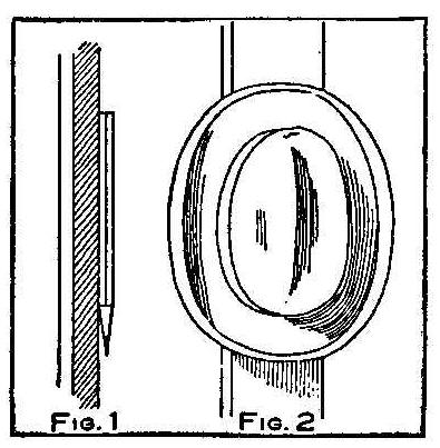
Take a smooth hexagon lead pencil, one without either rubber or
metal end, and place it against a door or window casing; then
with a firm, heavy pressure slide the pencil some 3 or 4 in. and
it will stay as if glued to the casing. You may now hang your hat
on the end of the pencil.
When you slide the pencil along the casing, do it without any
apparent effort, and it will appear to your audience as though
you had hypnotized it. This is a very neat trick if performed
right. Figure 1 shows the pencil on the casing and Fig. 2 the hat
hanging on it.
Tying a Knot for Footballs
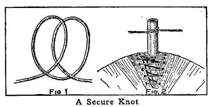
A Secure Knot
One of the most prominent English football clubs kept the tying
of this knot on the rubber hose of their football a secret and
never allowed all of its members to know how it was tied. This
tie can be used on grain sacks, and in numerous other like
instances. Make one loop in the cord and then another exactly the
same way, as shown in Fig. 1, placing the end of the cord under
the first loop, then pulling at each end of the cord as in Fig.
2.
A.E.J.
Stove Polish
Stove polish consists of 2 parts graphite, 4 parts copperas and 2
parts bone black, mixed with water to form a paste.
How to Give an Electric Shock While Shaking Hands
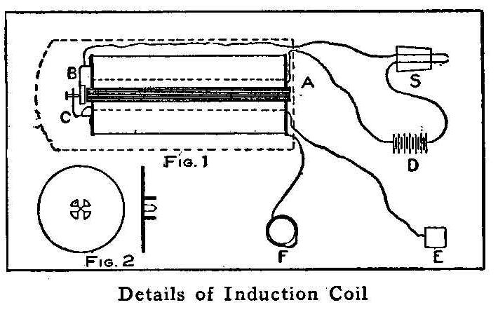
Details of Induction Coil
There is nothing quite so startling as to receive an electric
shock unexpectedly and such a shock may be given to a friend
while shaking hands upon meeting. The shock produced is not
harmful and the apparatus can be carried in the pocket. It
consists of a small induction coil that can be constructed at
home.
The core of the coil, A, Fig. 1, is constructed in the usual
manner, of small soft-iron wire to make a bundle about 3/16 in.
in diameter and 2 in. long. The coil ends are made from
cardboard, about 1 in. in diameter, with a 3/16-in. hole in the
center. The hole should be cut as shown in Fig. 2, so as to have
four small pieces that can be bent out, leaving the projections
as shown. After wrapping three or four turns of paper around the
bundle of wires the cardboard ends are put on with the
projections inside, so the coils of wire will hold them in place.
About 70 turns of No. 24 gauge double covered magnet wire is
first placed on the core, for the primary, and then 1,500 turns
of No. 32 or 34 gauge double-covered wire is wrapped on top of
the primary, for the secondary. Sufficient length of wire must be
left outside at each end of both windings to make connections.
The vibrator B, Fig. 1, and the support C are made from thin
spring steel, about 1/8 in. wide, bent as shown and securely
fastened to the cardboard end of the coil. The armature is made
from a soft piece of iron, about 3/16 in. in diameter and 1/16
in. thick, which is soldered to the end of the vibrator directly
opposite the end of the core. A small screw is fitted in the end
of the support, C, for adjustment, which should be tipped with
platinum and also a small piece of platinum placed where the
screw will touch the vibrator, B.
One of the primary wires is connected to the screw support. The
vibrator, is connected to a flash lamp battery, D. The other
primary wire is connected to a switch, S, which in turn is
connected to the other terminal of the battery. The switch, S,
may be made from a 3/8-in. cork with the wires put through about
3/16 in. apart and allow them to project about 1/2 in. The plate
E is cut about 1/2 in. square from a piece of copper and is
fastened to the heel of one shoe and connected with a wire from
the secondary coil which must be concealed inside of the trouser
leg. The other secondary wire is connected through the coat
sleeve to a finger ring, F. The vibrator screw must be properly
adjusted. When the vibrator is not working the armature should be
about 1/16 in. from the core and directly opposite.
The coil when complete will be about 2-1/2 in. long and 1 in. in
diameter. The coil can be placed in an old box that has been used
for talcum powder or shaving stick. The space around the coil in
the box can be filled with paper to keep it tight.
The coil and battery are carried in the pockets and the cork
button put in the outside coat pocket, where it can be pressed
without attracting attention.
Experiment with Heat
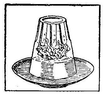
Place a small piece of paper, lighted, in an ordinary water
glass. While the paper is burning turn the glass over and set
into a saucer previously filled with water. The water will
rapidly rise in the glass, as shown in the sketch.
How to Attach a Combination Trunk Lock
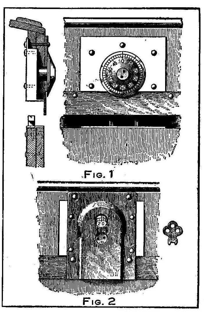
A small combination lock for chests can be purchased for a small
sum of money and attached to a trunk cover after first removing
the old lock as shown in Fig. 1. It is necessary to add 1/2-in.
to the thickness of the trunk lid or cover. This may be done by
placing a brass plate 1/8-in. thick on the outside and a board
3/8-in. thick on the inside. The lock, brass plate, board and
trunk cover are all securely riveted together. The support for
the dial is soldered to the brass plate.
The hasp, if that be the name for the double toothed arrangement
that catches into the lock, was to be secured by only three brass
screws, which seemed to be insufficient, says a correspondent of
the Metal Worker; therefore a piece of heavy tin was formed over
the front of the trunk, which is only 3/8-in. board, the hasp
tinned and soldered to the back of the now U-shaped tin, and the
tin placed over the board and all fastened in position. The tin
is 4 in. wide, 16 in. long and when placed over the board, it
laps down about 8 in. between the boards, and the same distance
inside of the new board, as shown by the heavy line in the cross
section, Fig. 1. Wrought nails are used which pass twice through
the tin and both boards, and then well clinched. The three screws
were then put in the hasp.
The knob on the dial extends out too far, which may be filed off
and two holes substituted, as shown, with which to operate the
dial. An old key is filed down in the shape shown in Fig. 2 to
fit the two holes. As the dial is convex it will need protection
to prevent injury by rough handling. A leather shield may be used
for this purpose, which is cut with two holes, one for the key
and the other to permit the operator to observe the numbers on
the dial. The shield answers a further purpose of preventing any
bystander from noting the numbers on the dial.
An Electric Illusion Box
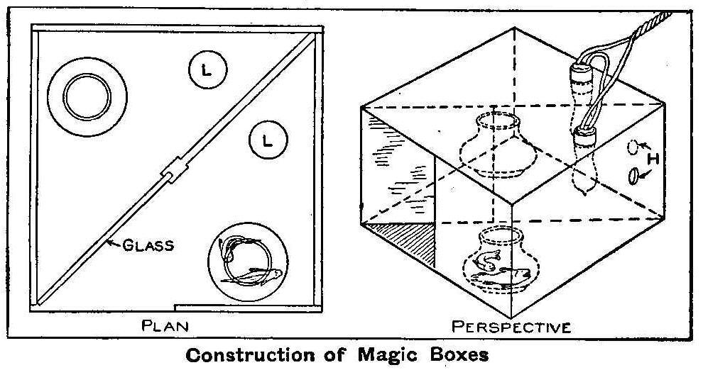
Construction of Magic Boxes
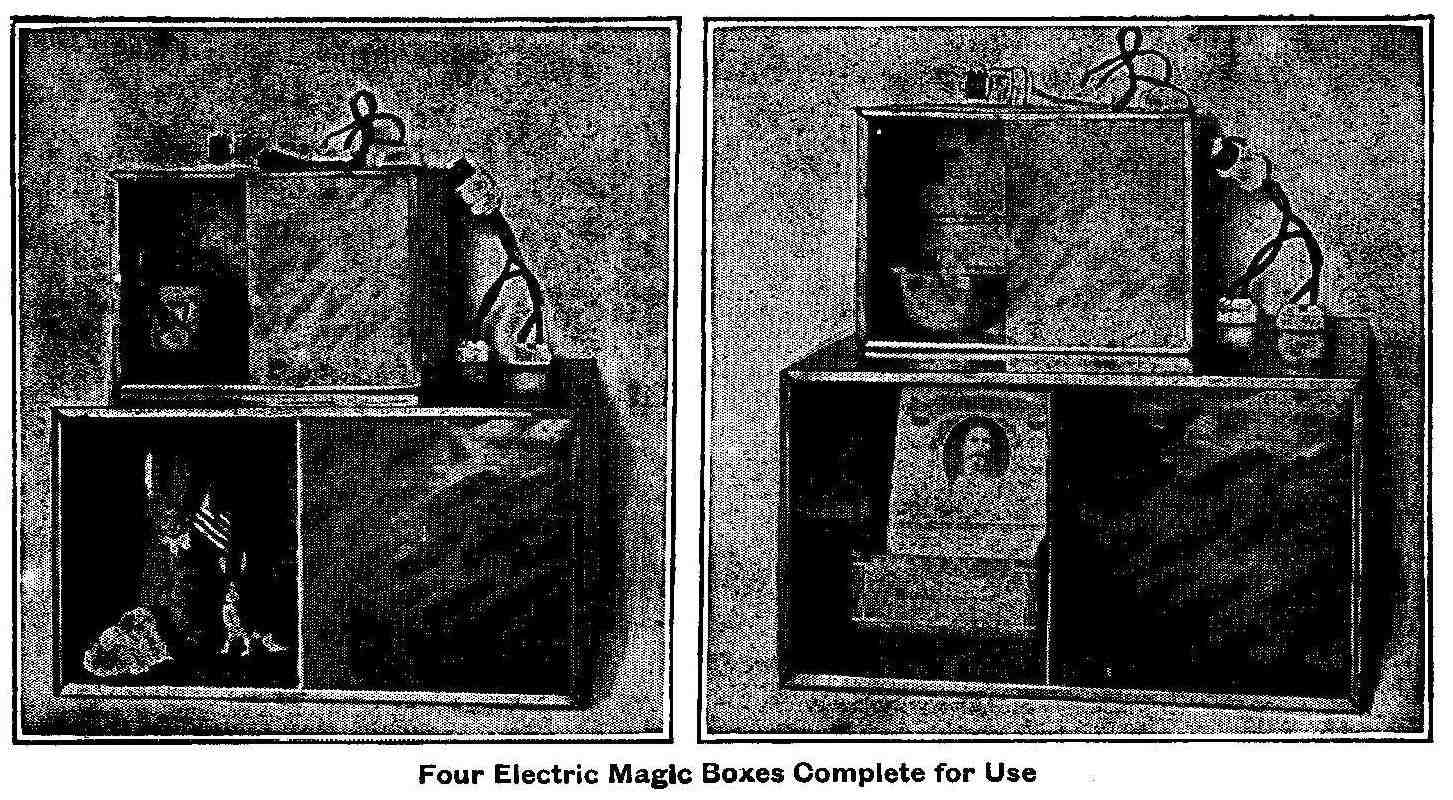
Four Electric Magic Boxes Complete for Use
The accompanying engravings show a most interesting form of
electrically operated illusion consisting of a box divided
diagonally and each division alternately lighted with an electric
lamp. By means of an automatic thermostat arranged in the lamp
circuit causing the lamps to light successively, an aquarium
apparently without fish one moment is in the next instant
swarming with live gold fish; an empty vase viewed through the
opening in the box suddenly is filled with flowers, or an empty
cigar box is seen and immediately is filled with cigars.
These electric magic boxes as shown are made of metal and
oxidized copper finished, but for ordinary use they can be made
of wood in the same shape and size. The upper magic boxes as are
shown in the engraving are about 12 in. square and 8-1/2 in. high
for parlor use and the lower boxes are 18 in. square and 10-1/2
in. high for use in window displays. There is a partition
arranged diagonally in the box as shown in the plan view, which
completely divides the box into two parts. One-half the partition
is fitted with a plain, clear glass as shown. The partition and
interior of the box are rendered non-reflecting by painting with
a dull, not shiny, black color. When making of wood, a door must
be provided on the side or rear to make changes of exhibits. If
the box is made large enough, or in the larger size mentioned,
openings may be made in the bottom for this purpose, and also
used in case of performing the magic trick of allowing two
persons to place their heads in the box and change from one to
the other. The electric globes are inserted as shown at LL
through the top of the box, one in each division. When the rear
part is illuminated, any article arranged within that part will
be visible to the spectator looking into the box through the
front opening, but when the front part is illuminated, and the
back left dark, any article placed therein will be reflected in
the glass, which takes the same position to the observer as the
one in the rear. Thus a plain aquarium is set in the rear part
and one with swimming fish placed in the front, and with the
proper illumination one is changed, as it appears, into the
other. When using as a window display, place the goods in one
part and the price in the other. Many other changes can be made
at the will of the operator.
Electric lamps may be controlled by various means to produce
different effects. Lamps may be connected in parallel and each
turned on or off by means of a hand-operated switch or the button
on the lamp socket, or if desired a hand-operated adjustable
resistance may be included in the circuit of each lamp for
gradually causing the object to fade away or reappear slowly.
Instead of changing the current operated by hand, this may be
done automatically by connecting the lamps in parallel on the
lighting circuit and each connected in series with a thermostatic
switch plug provided with a heating coil which operates to
automatically open and close the circuit through the respective
lamp.
When there is no electric current available, matches or candles
may be used and inserted through the holes H, as shown in the
sketch, alternately.
Replace Dry Putty
Painting over putty that has not become dry will cause scaling or
cracking around the edges of the putty.
Photo Print Washing Tank
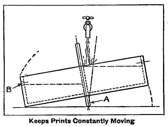
Keeps Prints Constantly Moving
The accompanying sketch shows a simple form of a print washing
tank that tips from side to side by the weight of the water. For
prints 4 by 5 and 5 by 7-in. a tank 2 ft. long and 1 ft. wide
will be about the right size. This tank is then divided with a
partition placed exactly in the center. This partition should
extend 3 or 4 in. above the top of the tank. The partition may
also extend below the tank about 1-1/2 in., or a piece of this
width put on the bottom, as shown at A in the sketch. A row of
holes about 1/2 in. in diameter is bored through each end of the
tank, as shown at B. These holes will allow the water to spill
out while the opposite side is filling. The tank may be made from
1/2-in. material and when completed as shown, lined with oil
cloth to make it watertight. The tank is placed with the
partition directly under a water tap and the flow of water will
cause it to tip from time to time, keeping the prints constantly
moving about in the water.
Home-Made Soldering Clamps
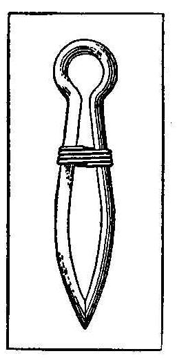
Take a cotter pin and bend it over a small rod to bring the
points together, as shown in the sketch. This will make a spring
clamp that is opened to slip over the articles to be clamped
together by inserting a scratch awl or scriber between the legs
at the bowed portion. To make a more positive clamp before
bending the legs to a bow, slip a short coil of wire over the
pin, passing it down to the ring end. Wire 1/32 in. in diameter
wound over a wire slightly larger in diameter than that of the
cotter will do. In soldering, smoke the legs well to avoid solder
adhering to them. The clamp is tightened by pushing up the coil
ring toward the bow of the legs and then twisting it like a nut,
the coil being wound right-handed, so that it will have a screw
effect.
A Telephone Experiment
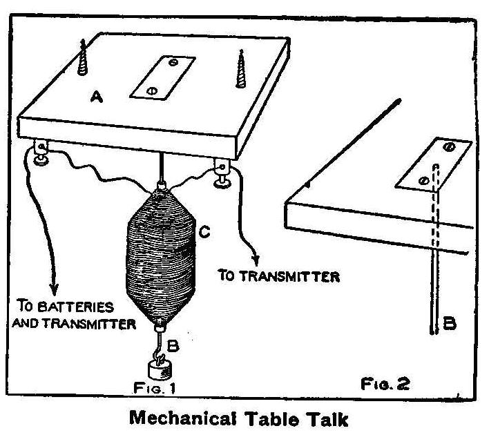
Mechanical Table Talk
If the small apparatus, as shown in the accompanying sketch, is
attached to the under side of an ordinary dining table, it will,
if connected to a telephone circuit, set the table in vibration,
so that any number of people who put their ears flat upon
the table will hear the voice of a person speaking from a
distance, apparently coming out of the table, says the Model
Engineer.
A small piece of wood, A, Fig. 1, is cut about 5 in. square, to
the center of which is attached a small piece of soft iron wire,
such as used for cores of induction coils, about 4 in. long and
bent in the form of a hook at the lower end, as shown at B. This
wire is attached to the block of wood, A, as shown in Fig. 2. The
end of the wire is soldered to a small brass plate which is set
in the block so it will be level or flush with the top of the
block and then fastened with two screws. The block A is fastened
to the under side of the table with two screws. A small coil, C,
is made by winding No. 24 silk or cotton covered wire around a
small tube, either a piece of glass, a short straw or a quill.
The coil is made tapering as shown without using wood ends. This
coil is slipped over the wire B previous to soldering it to the
small brass plate. The ends of the coil are connected to two
binding-posts which are fastened to the block A.
A small lead
weight weighing 2 or 3 oz. is hung on the hook made in the lower
end of the wire B.
When all connections are made, as shown in Fig. 1, and the block
fastened to the under side of the table, the apparatus is ready
for use, and has only to be connected to an ordinary telephone
transmitter and batteries as shown. The apparatus will work to a
certain extent even if the weight is removed, though not so
clear.
Wax Wood Screws
Some workmen use tallow on lag or wood screws. Try beeswax for
this purpose. It is much cleaner to use and is just as good if
not better.
How to Make an Induction Coil
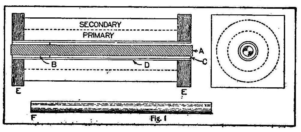
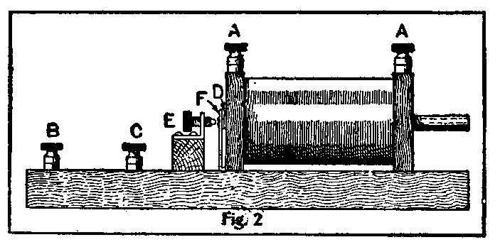
A small shocking coil, suitable for medical purposes, may be
constructed of materials found in nearly every amateur mechanic’s
collection of odds and ends. The core, A, Fig. 1, is a piece of
round soft iron rod about 1/4 in. in diameter and about 4 in.
long. A strip of stiff paper about 3/4 in. wide is covered with
glue and wrapped around one end of the core, as shown at B, until
the diameter is about 3/8 in. The portion of the core remaining
uncovered is then wrapped with a piece of paper about 4 in. wide.
No glue is used on this piece, as it is removed later to form the
space, C, after the paper shell, D, has been wound upon it. This
paper shell is made of stiff paper and glue the same as B and is
made about 3/64 in. thick. Two pieces of hardwood, EE, 1-3/4 in.
square and about 5/16 in. thick, are drilled in the center and
glued on the ends of the paper shell as shown.
The primary winding consists of 4 or 5 layers of No. 18 or 20
single cotton-covered magnet wire, the ends of which may be
passed through small holes in the wooden ends. If a drill small
enough is not available, the holes may be made with a hot
knitting needle or a piece of wire heated to redness. After the
primary coil is wound it should be thoroughly insulated before
winding the secondary. This may be done by wrapping with 4 or 5
thicknesses of paper.
The secondary coil should be wound with single covered wire,
preferably silk-covered, although cotton will do. The more turns
there are on the secondary the higher the voltage will be, so the
wire used must be fine. Number 32 to 36 will give good results,
the latter giving more voltage but less amperage. Each layer of
the secondary winding should be insulated from the others by a
piece of thin paraffined paper wrapped over each layer as it is
finished. It is well not to wind to the extreme ends of the paper
insulations, but to leave a space of about 1/8-in. at each end of
the winding to prevent the wires of one layer slipping over the
ends of the paraffin paper and coming in contact with the layer
beneath, thus causing a short circuit. The secondary winding
should have at least a dozen layers and should be carefully wound
to prevent short circuiting.
In order to reduce the strength of the current a piece of brass
tubing, F, is pushed into the space, C, surrounding the core, or
if no brass tubing of the required size is on hand, roll a paper
tube, cover with 4 or 5 thicknesses of tinfoil and then wrap with
more paper, using glue to hold the tinfoil in place and to keep
the tube from unwinding. When the tube is pushed all the way in,
the current produced will be almost unnoticeable, but when it is
withdrawn the current will be so strong that a person cannot let
go the handles until the coil is shut off. After the secondary
coil is wound it should be covered with stiff paper, and the
whole coil, including the wood ends, should then be enameled
black.
It is then ready to be mounted on a wooden base as shown in Fig.
2. The secondary terminals are connected to the binding-posts,
AA, which may be fastened on the base if desired. One wire from
the primary is connected with the binding-post, B, and the other
is connected with the armature, D, which may be taken from an old
electric bell. The contact screw, E, also from an electric bell,
is connected to the binding-post, C. The contact spring, F,
should be bent against and soldered to the armature in order to
make the vibrations more rapid.
If a false bottom is used on the base, all the wiring may be
concealed, which adds greatly to the appearance and if desired a
small switch may be added. The handles, which may be old bicycle
pumps or electric light carbons, are connected to the
binding-posts, AA, by means of wires about 3 or 4 ft. long. This
coil when operating with the tube pulled all the way out and
connected to a single dry cell will give a current stronger than
most persons can stand.
Home-Made Toaster
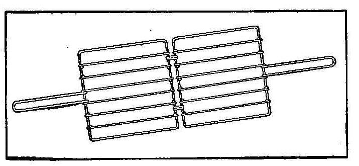
Each outside frame of the toaster is made from one piece of wire
30 in. long. These are bent in a perfect square making each side
7-in. long. This will allow 1 in. on each end for tying by
twisting the ends together. The first two wires inside and on
each side of each frame are 8 in. long. Eight wires will be
required for this purpose and as they are 8 in. long 1/2 in. is
allowed on each end for a bend around the outside frame, as shown
in the sketch. The two middle wires are extensions of the
handles. Each of these wires are made from a piece about 26 in.
long and bent in the shape of a U. The ends of the wire are bent
around the frame in the same manner as the other wires. This will
leave the handle laying across the other side of the frame. The
frame is fastened to the handle on this side by giving the handle
one turn around the frame. The inside edges of the frame are now
tied together with a small ring of wire which is loose enough to
allow each half to swing freely.
C. D. M.
Home-Made Shocking Machine
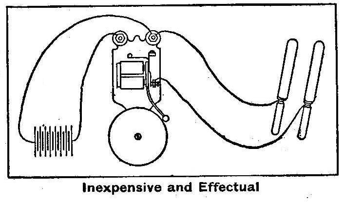
Inexpensive and Effectual
An ordinary electric bell may be connected up in such a way as to
produce the same results as an expensive shocking machine. The
connections are made from the batteries to the bell in the usual
manner. Two other wires are then connected, one to the
binding-post of the bell that is not insulated from the frame and
the other to the adjusting screw on the make and break contact of
the bell as shown in the sketch. The other ends of the wires are
connected each to a common table knife. This will give quite a
good shock and a much larger one can be had by placing one knife
in a basin of water and while holding the other knife in one
hand, dipping the fingers of the other hand in the water.
Contributed by D. Foster Hall.
Mahogany Wood Putty
Mix venetian red with quite thick arabic muscilage, making it
into a putty, and press this well into the cracks of mahogany
before finishing. The putty should be colored to suit the finish
of the wood, says the Master Painter, by adding such dry color to
the gum as will give the best result.
How to Make a Thermoelectric Battery
By Arthur E. Joerin
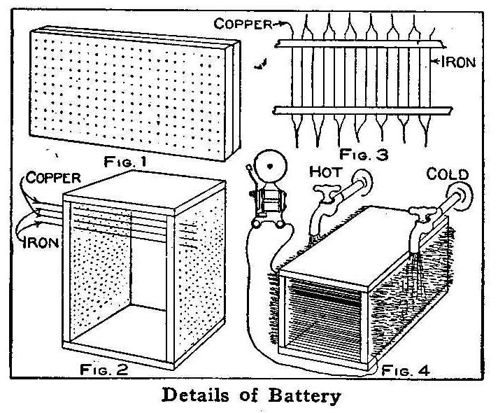
Details of Battery
A novel way of producing an electric current by means of hot and
cold water, heat from a match or alcohol lamp, is obtained from a
device constructed as shown in the sketch. Take two hardwood
boards, marble, or slate plates, about 8 or 10 in. long, place
them together, as in Fig. 1, and mark and drill about 500 holes.
These two pieces should be separated about 8 in. and fastened
with boards across the ends, as shown in Fig. 2.
Take soft copper wire, not smaller than No. 18 gauge, and cut in
lengths to pass through the holes in the two boards, leaving
sufficient end to make a tie. It will require about 70 ft. of
wire to fill one-half the number of holes. Also, cut the same
number of lengths from the same gauge galvanized-iron wire to
fill the remaining holes. The wires are put through the holes in
the boards alternately, that is: begin with copper, the next hole
with iron, the next copper, the next iron, and so on, twisting
the ends together as shown in Fig. 3. The connections, when
complete, should be copper for the first and iron for the last
wire.
When the whole apparatus is thus strung, the connections, which
must be twisted, can be soldered. Connect one copper wire to the
bell and the other terminal, which must be an iron wire, to the
other post of the bell. The apparatus is then short-circuited,
yet there is no current in the instrument until a lighted match,
or, better still, the flame of an alcohol lamp is placed at one
end only.
Best results are obtained by putting ice or cold water on one
side and a flame on the other. The experimenter may also place
the whole apparatus under sink faucets with the hot water turned
on at one terminal and the cold water at the other. The greater
the difference of temperature in the two terminals, the more
current will be obtained.
Very interesting experiments may thus be performed, and these may
lead to the solving of the great thermoelectric problem.
How to Make a Hygrometer
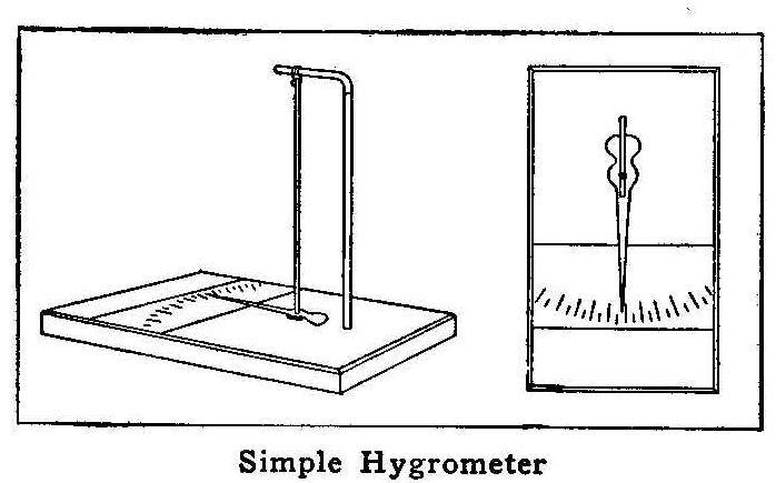
Simple Hygrometer
Mount a wire on a board which is used for a base and should be
3/8 by 4 by 8 in., as shown in the sketch. A piece of catgut—a
string used on a violin will do—is suspended from the bent end
of the wire. A hand or pointer is cut from a piece of tin and
secured to the catgut string about 1/2 in. from the base. A small
piece of wood and some glue will fasten the pointer to the
string. The scale is marked on a piece of cardboard, which is
fastened to the base and protected with a piece of
glass.
Contributed by J. Thos. Rhamstine.
Softening Leather in Gloves and Boots
The leather in high-top boots and gauntlet gloves may be softened
and made waterproof by the use of plain mutton tallow. Apply hot
and rub in well with the fingers.
How to Make a Mission Library Table
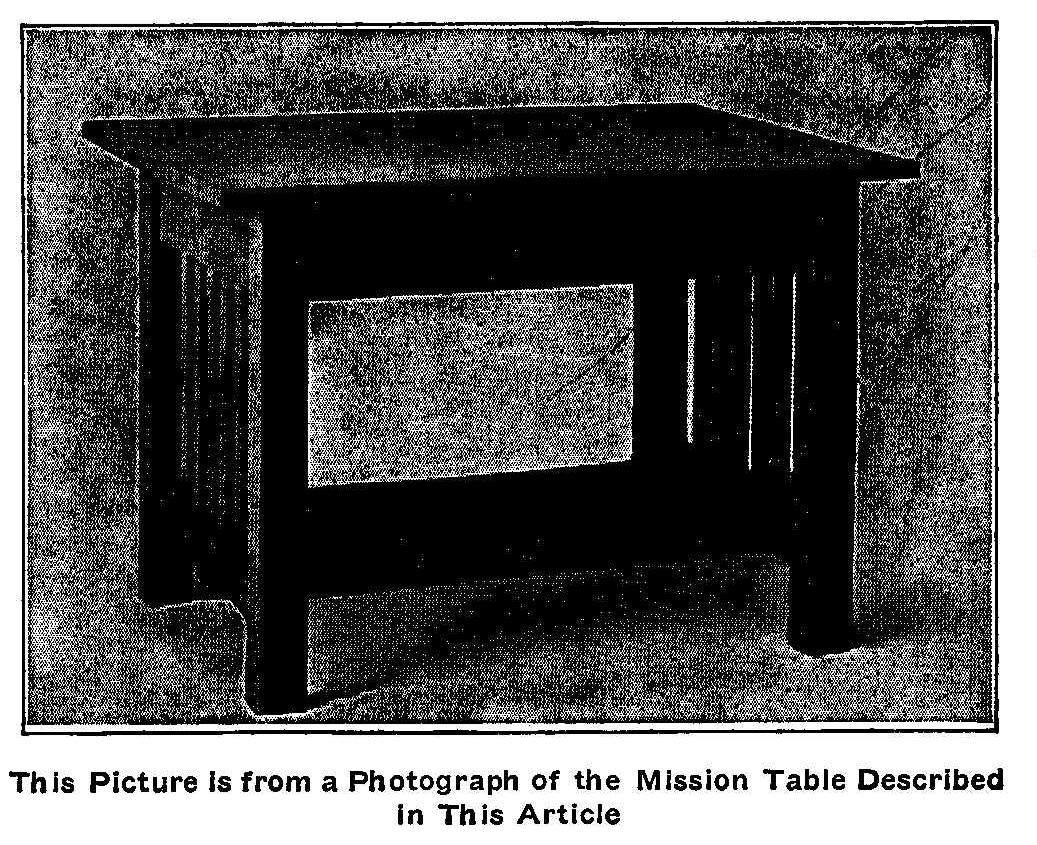
This Picture Is from a Photograph of the Mission Table Described
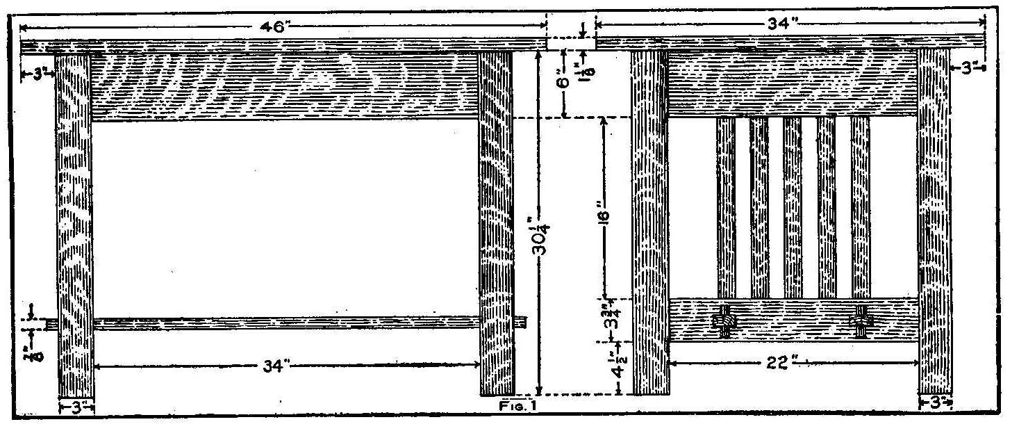
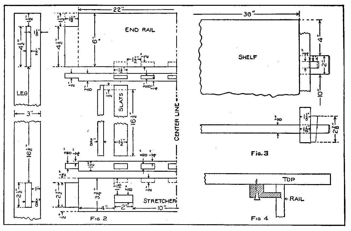
The mission library table, the drawings for which are here given,
has been found well proportioned and of pleasing appearance. It
can be made of any of the several furniture woods in common use,
such as selected, quarter-sawed white oak which will be found
exceptionally pleasing in the effect produced.
If a planing mill is at hand the stock can be ordered in such a
way as to avoid the hard work of planing and sandpapering. Of
course if mill-planed stock cannot be had, the following
dimensions must be enlarged slightly to allow for “squaring up
the rough.”
For the top, order 1 piece 1-1/8 in. thick, 34 in. wide and 46
in. long. Have it S-4-S (surface on four sides) and “squared” to
length. Also, specify that it be sandpapered on the top surface,
the edges and ends.
For the shelf, order 1 piece 7/8 in. thick, 22 in. wide and 42
in. long, with the four sides surfaced, squared and sandpapered
the same as for the top. For the side rails, order 2 pieces 7/8
in. thick, 6 in. wide and 37 in. long, S-4-S and sanded on one
side. For the end rails, 2 pieces 7/8 in. thick, 6 in. wide and
25 in. long. Other specifications as for the side rails.
For the stretchers, into which the shelf tenons enter, 2 pieces
1-1/8 in. thick, 3-3/4 in. wide and 25 in. long, surfaced and
sanded on four sides. For the slats, 10 pieces 5/88 in. thick,
1-1/2 in. wide and 17 in. long, surfaced and sanded on four
sides. For the keys, 4 pieces 3/4 in. thick, 1-1/4 in. wide and
2-7/8 in. long, S-4-S. This width is a little wide; it will allow
the key to be shaped as desired.
The drawings obviate any necessity for going into detail in the
description. Fig. 1 gives an assembly drawing showing the
relation of the parts. Fig. 2 gives the detail of an end. The
tenons for the side rails are laid off and the mortises placed in
the post as are those on the end. Care must, be taken, however,
not to cut any mortises on the post, below, as was done in
cutting the stretcher mortises on the ends of the table. A good
plan is to set the posts upright in the positions they are to
occupy relative to one another and mark with pencil the
approximate positions of the mortises. The legs can then be laid
flat and the mortises accurately marked out with a fair degree of
assurance that they will not be cut where they are not wanted and
that the legs shall “pair” properly when effort is made to
assemble the parts of the table.
The table ends should be glued up first and the glue allowed to
harden, after which the tenons of the shelf may be inserted and
the side rails placed.
There is a reason for the shape, size and location of each tenon
or mortise. For illustration, the shape of the tenon on the top
rails permits the surface of the rail to extend almost flush with
the surface of the post at the same time permitting the mortise
in the post to be kept away from that surface. Again, the shape
of the ends of the slats is such that, though they may vary
slightly in length, the fitting of the joints will not be
affected. Care must be taken in cutting the mortises to keep
their sides clean and sharp and to size.
In making the mortises for the keyed tenons, the length of
mortise must be slightly in excess of the width of the
tenon—about 1/8-in. of play to each side of each tenon. With a
shelf of the width specified for this table, if such allowance is
not made so that the tenons may move sideways, the shrinkage
would split the shelf.
In cutting across the ends of the shelf, between the tenons,
leave a hole in the waste so that the turning saw or compass saw
can be inserted. Saw within one-sixteenth of the line, after
which this margin may be removed with chisel and mallet.
In Fig. 3 is shown two views of the keyed tenon and the key. The
mortise for the key is to be placed in the middle of the tenon.
It will be noted that this mortise is laid out 1-1/16 in. from
the shoulder of the tenon while the stretcher is 1-1/8 in. thick.
This is to insure the key’s pulling the shelf tightly against the
side of the stretcher.
Keys may be made in a variety of shapes. The one shown is simple
and structurally good. Whatever shape is used, the important
thing to keep in mind is that the size of the key and the slant
of its forward surface where it passes through the tenon must be
kept the same as the mortise made for it in the tenon.
The top is to be fastened to the rails by means either of wooden
buttons, Fig. 4, or small angle irons.
There are a bewildering number of mission finishes upon the
market. A very satisfactory one is obtained by applying a coat of
brown Flemish water stain, diluted by the addition of water in
the proportion of 2 parts water to 1 part stain. When this has
dried, sand with number 00 paper, being careful not to “cut
through.” Next, apply a coat of dark brown filler; the directions
for doing this will be found upon the can in which the filler is
bought. One coat usually suffices. However, if an especially
smooth surface is desired a second coat may be applied in a
similar manner.
After the filler has hardened, a very thin coat of shellac is to
be put on. When this has dried, it should be sanded lightly and
then one or two coats of wax should be properly applied and
polished. Directions for waxing are upon the cans in which the
wax is bought. A beautiful dull gloss so much sought by finishers
of modern furniture will be the result of carefully following
these directions.
A Hanger for Trousers
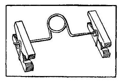
Secure two clothes pins of the metal spring kind for the clamps
of the hanger. The pins are fastened one to each end of a looped
galvanized wire. This wire should be about 6 in. long after a
coil is bent in the center as shown in the sketch. The diameter
of the wire should be about 1/8 in.
How to Make an Adjustable Negative Washer
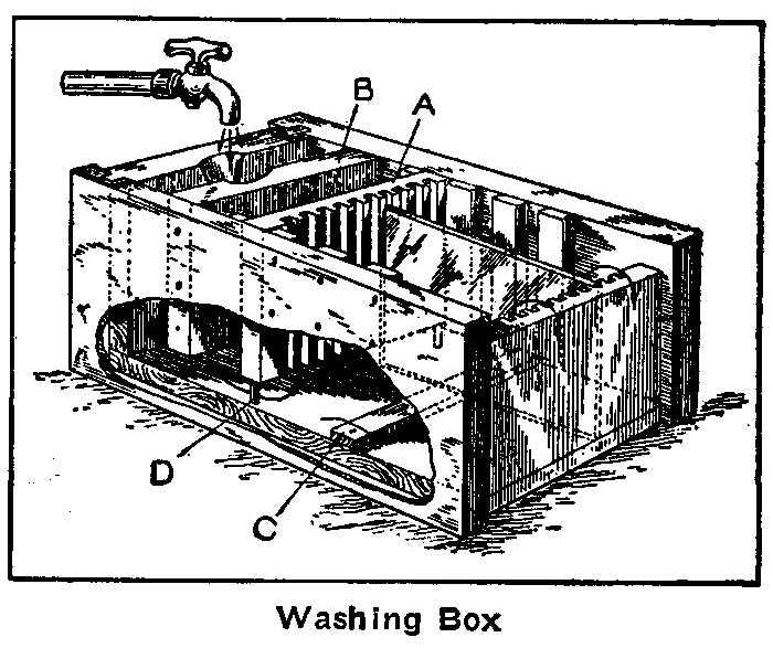
Washing Box
The sketch herewith shows a washing box for negatives made from
an ordinary wooden box. As can be seen, the grooved partition, A,
is removable, and as several places are provided for its
insertion, the tank can be made to accommodate anyone of several
sizes of plates, says Camera Craft. The other stationary
partition, B, which does not reach quite to the bottom of the
tank, is placed immediately next to the end of the tank, leaving
a channel between the two for the inflow of the wash water. A
narrow, thin strip, C, is fastened to the bottom of the tank to
keep the plates slightly raised, at the same time allowing a
clearer flow of the water from the bottom upwards to the
discharge.
The water enters the narrow partition at the end, flows under the
partitions B and A, then upward between and parallel to the
surface of the plates, escaping at the opposite end over the top
of the tank end, in which the upper part has been cut away for
that purpose. The depth of this cut, in the upper part of the
tank end, should allow the overflow to be a trifle higher than
the width of the largest size plate for which the tank is fitted.
Partition B being stationary, can be nailed in position
permanently, allowing the bottom edge to clear the bottom of the
tank the desired distance. Partition A being movable should have
attached to its bottom edge a couple of nails, D, or better
still, wooden pegs, which will keep it also above the bottom of
the tank at the desired height.
A coat of paraffin paint should be applied, and, just before it
sets perfectly hard, any rough spots trimmed down with a knife or
chisel and a second lighter coat applied. If the wood is very dry
and porous a preliminary coat of the paint should be applied and
allowed to soak into the pores. It is also well to apply a coat
of the paint to the joints at the corners and around the edge of
the bottom before nailing together.
Turn-Down Shelf for a Small Space
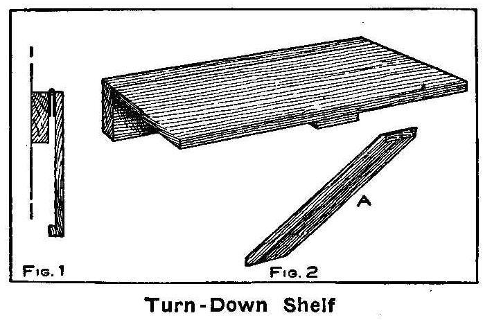
Turn Down Shelf
The average amateur photographer does not have very much space in
which to do his work. The kitchen is the room used ordinarily for
finishing the photographs. In many instances there will not be
space enough for any extra tables, and so a temporary place is
prepared from boxes or a chair on which to place the trays and
chemicals. Should there be space enough on one of the walls a
shelf can be made to hang down out of the way when not in use. A
shelf constructed on this order may be of any length to suit the
space or of such a length for the purpose intended. A heavy piece
of wood, about 1-1/2 in. thick, and 4 to 6 in. wide, is first
fastened to the wall at the proper height with nails, or, much
better, large screws.
The shelf is cut and planed smooth from a board 12-in. wide and
about 1-in. thick. This board is fastened to the piece on the
wall with two hinges as shown in Fig. 1. A small cleat is nailed
to the outer and under edge of the board and in the middle as
shown. This is used to place a support under the outer edge of
the shelf. The support, A, Fig. 2, should be long enough to
extend diagonally to the floor or top of the baseboard from the
inner edge of the cleat when the shelf is up in its proper place.
L. L.
Home-Made Electric Battery Massage
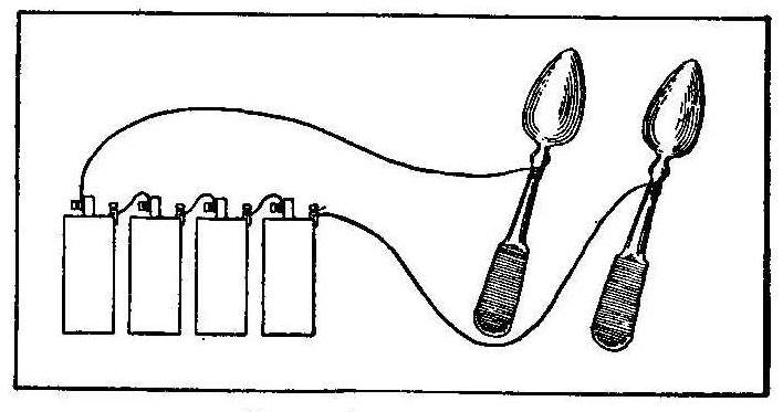
Electric Message
A simple and cheap electric massage device can be made by using
three or four cells of dry battery connected to two ordinary
silver tablespoons, as shown in the sketch. The handles of the
spoons should be insulated or the operator can wear either kid or
rubber gloves.
How to Make Tint Lantern Slides
Purchase some lantern slide plates and fix them in hypo without
exposing, in the usual manner, same as you would an exposed
plate, says the Moving Picture World. This leaves a thin,
perfectly transparent emulsion film on the glass, which will
readily take color. Mix a rather weak solution of clear aniline
dye of the desired color and dip the plate in it, wiping the
plate side clean. If not dark enough, dip again and again until
desired tint is attained, letting it dry between each dipping. A
very light blue tint slide will brighten a yellow film
considerably, but the tint must be very light, just a bare tint.
A Bicycle Catamaran
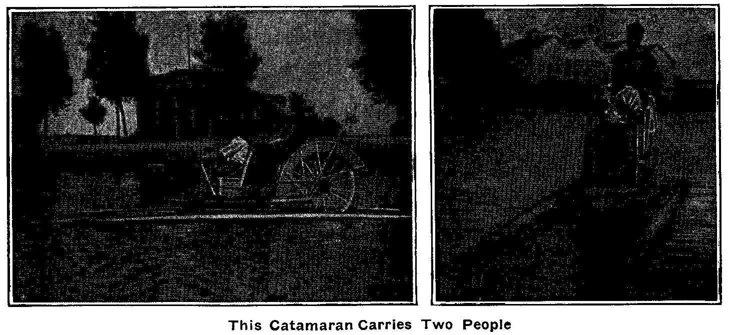
This Catamaran Carries Two People
The accompanying photographs show a bicycle boat made to carry
two persons. This boat is constructed by using two galvanized
iron tubes 18 ft. long and 12 in. in diameter, tapered at the
front end down to cast-iron points, and the rear end shaped to
attach rudders. These tubes are placed 26 in. apart, giving the
boat an extreme width of 50 in.
The cylinders support a platform and on the rear end of this
platform is constructed a paddle wheel 52 in. in diameter with 16
spokes. On the end of each spoke is fastened a galvanized sheet
metal blade 6 in. wide and 8 in. long. A large guard placed over
the paddle wheel forms a seat for one person and a chair in front
on the platform provides a place for a second person.
The person in front helps to propel the boat with hand levers
which are connected with rods to sprocket wheels on each side of
the platform. The occupant of the rear seat contributes his part
of the power with his feet on pedals of the shaft that carries
the sprocket wheels. This shaft and sprocket wheels drive the
paddle wheel by side chains of the bicycle kind. The boat is
steered from the rear seat by ropes attached to double rudders.
This boat will run at considerable speed and is very steady in
rough water as it goes directly through large waves instead of
going over them.
Contributed by Ernest Schoedsack, Council Bluffs, Iowa.
How to Make a Lead Pencil Rheostat
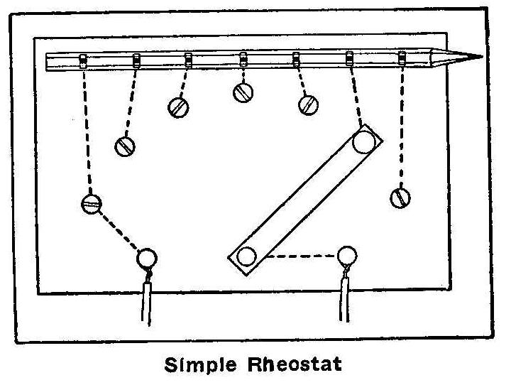
Simple Rheostat
Take an ordinary lead pencil and cut seven notches at equal
intervals on the pencil down to and around the lead, leaving it
bare. A seven-point switch is constructed on a board of suitable
size making the points by using screws that will go through the
board. A small piece of tin or brass will do for a switch and is
fastened as shown. The connections are made on the back side of
the board as shown by the dotted lines. This will reduce 40 to 50
volts down to 5 or 10 volts for short lengths of
time.
Contributed by Roy Newby, San Jose, Cal.
Homemade Shoe Rack
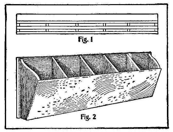
The accompanying sketch explains how a boy can make his own shoe
rack that can be placed on the wall in the clothes closet. Figure
1 shows the construction of the bottom to permit the dirt to fall
through. Two boards, 9 in. wide and about 3 ft. long, with six
partitions between, as shown, will make pockets about 6 in. long.
The width of the pockets at the bottom is 2 in. and at the top 5
in.
Contributed by Guy H. Harvey, Mill Valley, Cal.
How to Waterproof Canvas
The method used by the British navy yards for waterproofing and
painting canvas so it will not become stiff and cracked is as
follows: One ounce of yellow soap and 1/2 pt. of hot water are
mixed with every 7 lb. of paint to be used. The mixture is
applied to the canvas with a brush. This is allowed to dry for
two days and then a coat of the same paint, without the soap, is
laid on. When this last coat is dry the canvas may be painted any
color desired. After three days of drying the canvas may be
folded up without sticking together, and is, of course,
waterproof. Canvas waterproofed in this manner makes an excellent
covering for portable canoes and canvas boats. The color
mixture for the soap and second application is made from 1 lb. of
lampblack and 6 lb. of yellow ocher, both in oil; the finish coat
may be any color desired. When no paint is to be used on the
canvas it may be waterproofed with a mixture made from soft soap
dissolved in hot water, and a solution of iron sulphate added.
Iron sulphate, or ferrous sulphate, is the green vitriol. The
vitriol combines with the potash of the soap, and the iron oxide
is precipitated with the fatty acid as insoluble iron soap. This
precipitate is then washed, dried and mixed with linseed oil.
Building a House in a Tree Top
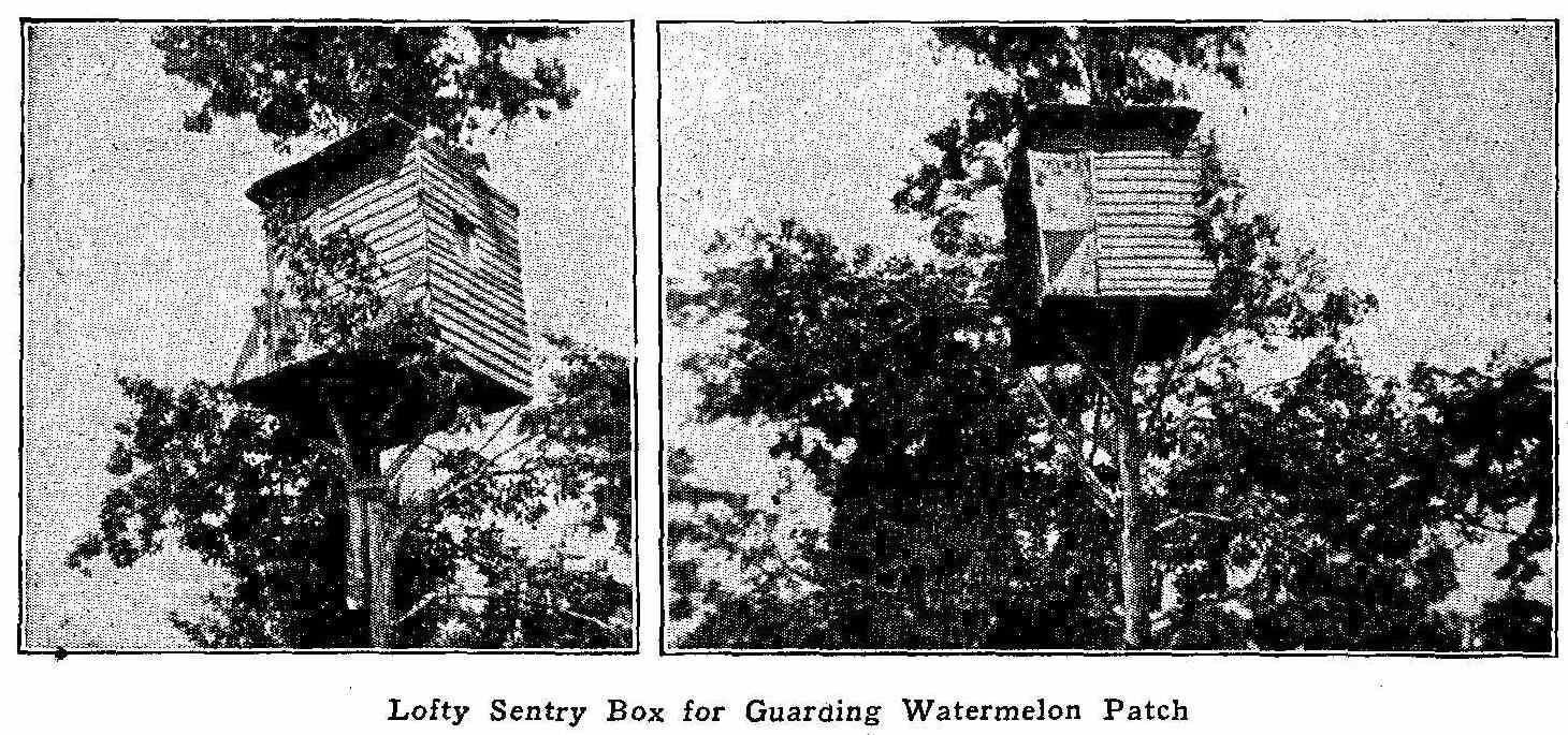
Lofty Sentry Box for Guarding Watermelon Patch
The accompanying photograph shows a small house built in a tree
top 20 ft. from the ground. The house is 5 ft. wide, 5 ft. 1 in.
long, and 6 ft. 6 in. high. A small platform, 2 ft. wide, is
built on the front. Three windows are provided, one for each
side, and a door in front. The entrance is made through a trap
door in the floor of the house. This house was constructed by a
boy 14 years old and made for the purpose of watching over a
melon patch.
Contributed by Mack Wilson, Columbus, O.
How to Make a Lamp Stand and Shade
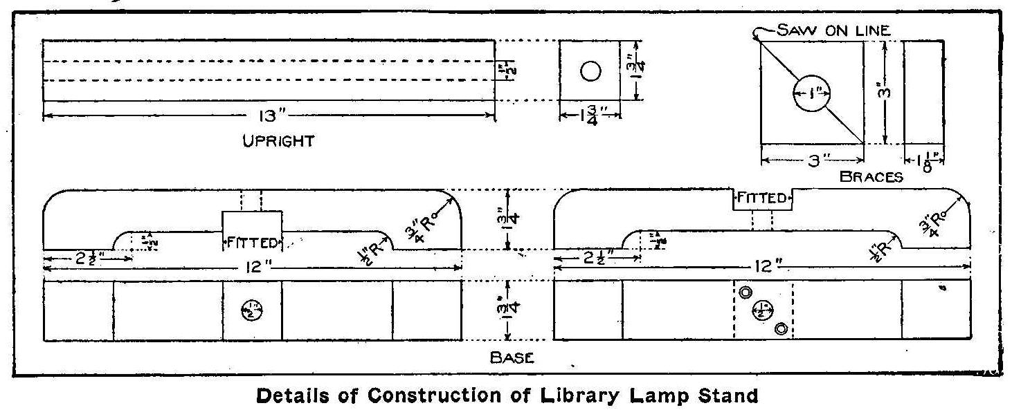
Details of Construction of Library Lamp Stand
A library light stand of pleasing design and easy construction is
made as follows: Square up a piece of white oak so that it shall
have a width and thickness of 1-3/4 in. with a length of 13 in.
Square up two pieces of the same kind of material to the same
width and thickness, but with a length of 12 in. each. Square up
two pieces to a width and length of 3 in. each with a thickness
of 1-1/8 in.
If a planing mill is near, time and patience will be saved by
ordering one piece 1-3/4 in. square and 40 in. long, two pieces
1-1/8 in. thick and 3 in. square, all planed and sandpapered on
all surfaces. The long piece can then be cut at home to the
lengths specified above.
The 13-in. piece is for the upright and should have a 1/2-in.
hole bored the full length through the center. If the bit is not
long enough to reach entirely through, bore from each end, then
use a red-hot iron to finish. This hole is for the electric wire
or gas pipe if gas is used.
The two pieces for the base are alike except the groove of one is
cut from the top and of the other from the under side, as shown.
Shape the under sides first. This can best be done by placing the
two pieces in a vise, under sides together, and boring two holes
with a 1-in. bit. The center of each hole will be 2-1/2 in. from
either end and in the crack between the pieces. The pieces can
then be taken out, lines gauged on each side of each, and the
wood between the holes removed with turning saw and scraper
steel.
The width of the grooves must be determined by laying one piece
upon the other; a trysquare should be used to square the lines
across the pieces, however, gauge for depth, gauging both pieces
from their top surfaces. Chisel out the grooves and round off the
corners as shown in the sketch, using a 3/4-in. radius.
These parts may be put together and fastened to the upright by
means of two long screws from the under side, placed to either
side of the 1/2-in. hole. This hole must be continued through the
pieces forming the base.
The braces are easiest made by taking the two pieces which were
planed to 1-1/8 in. thick and 3 in. square and drawing a diagonal
on each. Find the middle of this diagonal by drawing the central
portion of the other diagonal; at this point place the spur of
the bit and bore a 1-in. hole in each block.
Saw the two blocks apart, sawing along a diagonal of each. Plane
the surfaces on the saw cut smooth and sandpaper the curve made
by the bit. Fasten the braces in place by means of roundhead
blued screws.
To make a shade such as is shown in the illustration is rather
difficult. The shade is made of wood glued up and has art glass
fitted in rabbets cut on the inner edges. Such shades can be
purchased ready to attach. The sketch shows one method of
attaching. Four small pieces of strap iron are bent to the shape
shown and fastened to the four sides of the upright. Electric
globes—two, three or four may be attached as shown.
The kind of wood finish for the stand will depend upon the finish
on the wooden shade, if shade is purchased. Brown Flemish is
obtained by first staining the wood with Flemish water stain
diluted by the addition of two parts water to one part stain.
When this is dry, sandpaper the “whiskers” which were raised by
the water and fill with a medium dark filler. Directions will be
found on the filler cans. When the filler has hardened, apply
two coats of wax.
The metal shade as shown in the sketch is a “layout” for a copper
or brass shade of a size suitable for this particular lamp. Such
shades are frequently made from one piece of sheet metal and
designs are pierced in them as suggested in the “layout.” This
piercing is done by driving the point of a nail through the metal
from the under side before the parts are soldered or riveted
together. If the parts are to be riveted, enough additional metal
must be left on the last panel to allow for a lap. No lap is
needed when joints are soldered.
A better way, and one which will permit the use of heavier metal,
is to cut each side of the shade separately and fasten them
together by riveting a piece of metal over each joint. The shape
of this piece can be made so as to accentuate the rivet heads and
thus give a pleasing effect.
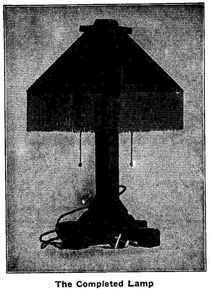
The Completed Lamp
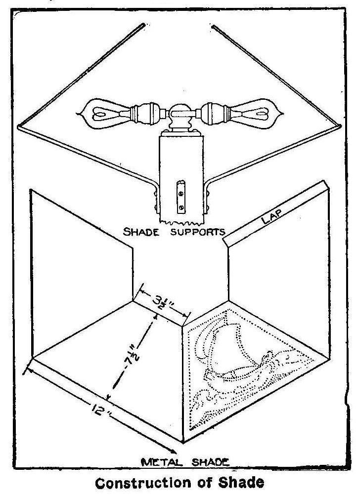
Metal Shade—Construction of Shade
For art-glass the metal panels are cut out, the glass is inserted
from the under side and held in place by small clips soldered to
the frame of the shade. Pleasing effects are obtained by using
one kind of metal, as brass, and reinforcing and riveting with
another metal, such as copper.
Illuminating a Watch Dial at Night
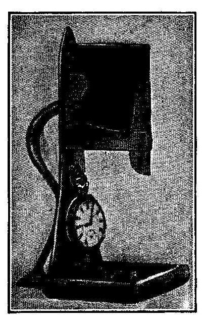
This picture shows a watch holder, with a device to receive an
ordinary electric pocket lamp and battery. The battery is set in
a bracket under which a reflector extends downward to throw the
light on the dial of the watch and to protect the eyes from the
direct light. The entire stand and bracket are made from sheet
metal. The base is formed to make a tray to hold pins and collar
buttons. It is not necessary to seek in the darkness for a push
button or switch, as in ordinary devices, but a light pressure
with the palm of the hand will make the lamp glow.
Home-Made Photographic Copying Stand
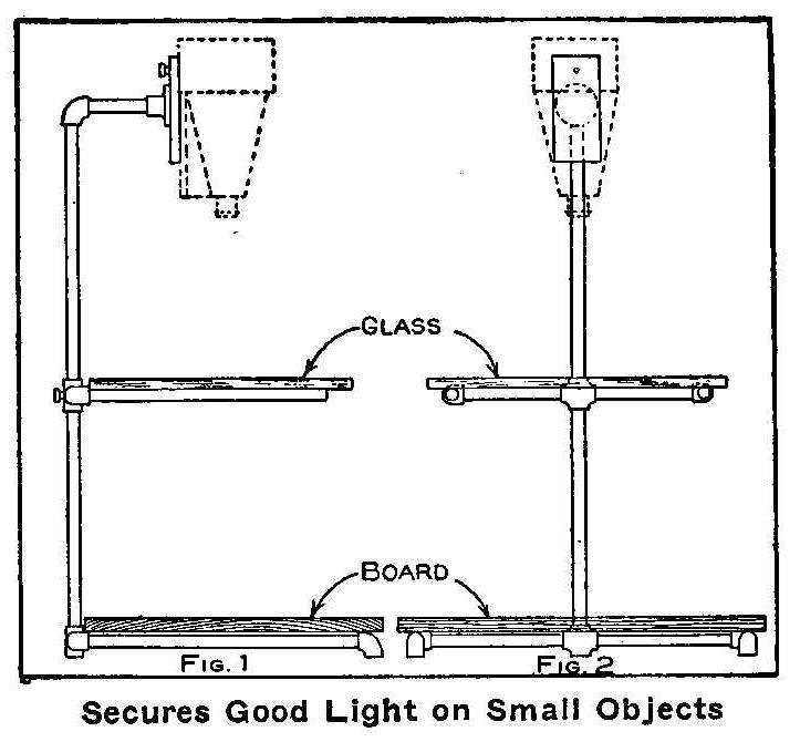
Secures Good Light on Small Objects
The difficulties of bad lighting on small articles can be
entirely avoided by the use of a suitable support for the camera,
the object and the background. For illustrations it is often an
advantage to show an object with a perfectly plain background and
no deep shadows. When using the stand as illustrated this is a
very simple matter. Figure 1 shows the side, and Fig. 2 the front
view of this stand. The stand is very easily constructed from
pipe and pipe fittings. The main pipe of the stand will need to
be of proper length to suit the focus of your camera. This can be
determined by finding the length from the lens to the object
after the bellows are extended to their full length. The arms
holding the glass, as shown in the sketch, should be set at a
point about the middle of the main tube. The cross that holds the
middle arms should be 3/4 in. one way and 1/2 in. the other. This
will allow for adjustment of the glass table. A small set screw
provided in the back of this cross will hold the table in any
position desired. The pipes and other connections are all 1/2-in.
and the lengths of the pipes are made suitable for the size of
the camera. When a small object is to be photographed it is
placed upon the glass table and the background fastened to the
board. In this manner small objects can be photographed without
any deep shadow on one side. The bottom cross and ells should be
corked so as to prevent any slipping and damage to the floor.
Home-Made Pocket Lamp
A simple and safe pocket lamp that will last for about 6 months
without extra expense can be made at home for a few cents.
Have your druggist take a strong vial of clear glass, or a pill
bottle with screw or cork top and put into it a piece of
phosphorus about the size of a pea and fill the bottle one-third
full of pure olive oil that has been heated for 15 minutes—but
not boiled. Cork tightly and the result will be a luminous light
in the upper portion of the bottle. If the light becomes dim,
uncork and recork again. The lamp will retain its brilliancy for
about 6 months. This makes a perfectly safe lamp to carry. These
lamps are used by watchmen of powder magazines.
Care should be
exercised in handling the phosphorus,
as it is very poisonous.
How to Make a Tangent Galvanometer
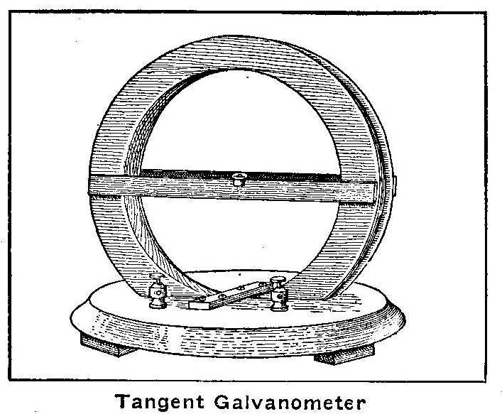
Tangent Galvanometer
Secure a piece of wood 1/2 in. thick and cut out a ring with an
outside diameter of 10-1/2 in. and an inside diameter of 9 in.
and glue to each side two other rings 1/4 in. thick with the same
inside diameter as the first ring and 11 in. outside diameter,
thus forming a 1/4-in. channel in the circumference of the ring.
If a lathe is at hand this ring can be made from a solid piece
and the channel turned out. Cut another circular piece 11 in. in
diameter for a base. Make a hole in the center of this piece 1
in. wide and 6-5/16 in. long, into which the ring first made
should fit so that its inner surface is just even with the upper
surface of the baseboard. The ring is held upright in the hole by
a small strip screwed to the base as shown. All screws and brads
that are used must be of brass. The cutting of these circular
pieces is not so difficult if a band saw driven by power is used.
They can be cut by means of a key-hole saw if a band saw is not
accessible.
Before mounting the ring on the base, the groove should be wound
with 8 turns of No. 16 double cotton-covered magnet wire. The two
ends may be tied together with a string to hold them temporarily.
Fasten two strips of wood 1/4-in. thick 5/8-in. wide and 11 in.
long across the sides of the ring with their upper edges passing
exactly through the center of the ring. An ordinary pocket
compass, about 1-1/4 in. in diameter, is fitted in these strips
so that the center of the needle or pointer will be exactly in
the center of the ring and its zero point mark at the half-way
point between the two strips. Put the ring in place on the base,
as shown in the sketch, and connect the two ends of the wire to
two binding-posts that are previously attached to the base. Coat
the entire surface with brown shellac. Any deviation from the
dimensions will cause errors in the results obtained by its use.
Remove all pieces of iron or steel and especially magnets in the
near vicinity of the instrument when in use. Place the
galvanometer on a level table and turn it until the needle,
pointing north and south, and swinging freely, lies exactly in
the plane of the coil, as shown in the cut. The needle then will
point to zero if the directions have been followed closely.
Connect one cell of battery to the instrument and allow the
current to flow through the coils. The needle of the compass will
be deflected to one side or the other, and will finally come to
rest at a certain angle-let us say 45 deg. The dimensions of the
instrument are such that when the deflection is 45 deg. the
current flowing through the coils upon the ring is 1/2 ampere.
The ampere is the unit chosen to designate the strength of the
electric current. For other angles the value of the current may
be found from the following table:
| Angles Degrees | Current Amperes |
| 10 | .088 |
| 20 | .182 |
| 30 | .289 |
| 40 | .420 |
| 45 | .500 |
| 50 | .600 |
| 55 | .715 |
| 60 | .865 |
| 70 | 1.375 |
As the magnetic force that acts upon a magnet needle varies in
different places the values given for the current will not be
true in all parts of the country. The table gives correct values
for the immediate vicinity of Chicago and that part of the United
States lying east of Chicago, and north of the Ohio river. The
results given should be multiplied by 1.3 for places south of the
Ohio river and east of the Mississippi.
Home-Made X-Ray Instrument
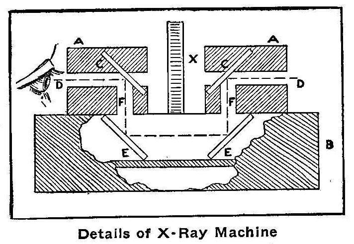
Details of X-Ray Machine
Two cylinders, AA, are mounted on a base, B, and mirrors, CC, are
fitted at an angle of 45 deg. into these cylinders. Corresponding
mirrors, EE, are put in the base parallel with those in those
cylinders. An opening extends downward from D of each cylinder so
that light entering at one end of the cylinder is reflected down
at right angles by the first mirror to the second, from the
second to the third, from the third to the fourth which reflects
the light to the eye. Thus the light never passes through the
cylinders and the observer does not see through, but around any
object inserted at X between the cylinders.
How to Make a a Non-Polarizing Battery
Bichromate batteries are very expensive to maintain and dry cells
do not furnish enough amperage for some kinds of experimental
work. A cell of a battery that will run 10 hours with an output
of over 1 ampere can be made as follows: Secure a jar about 4 in.
in diameter and 8 in. high and place in the bottom of this jar
the lower half of a tin baking powder can, to which a wire has
been soldered for connections. Place in the can a mixture of 2
oz. black oxide of copper, 1 oz. black oxide of manganese and
some iron filings.
Purchase a small crowfoot zinc and hang it about 1 in. above the
half can. Prepare a 10 per cent solution of caustic soda and fill
the jar within 1 in. of the top. Place on top the solution a thin
layer of kerosene or paraffin. The cell will only cost about 50
cents to make and 25 cents for each renewal. When renewing,
always remove the oil with a siphon.
Contributed by Robert Canfield, University Park, Colo.
A Home-Made Barometer
Take 1/4 oz. of pulverized camphor, 62 gr. of pulverized nitrate
of potassium, 31 gr. nitrate of ammonia and dissolve in 2 oz.
alcohol. Put the solution in a long, slender bottle, closed at
the top with a piece of bladder’ containing a pinhole to admit
air, says Metal Worker. When rain is coming the solid particles
will tend gradually to mount, little crystals forming in the
liquid, which otherwise remains clear; if high winds are
approaching the liquid will become as if fermenting, while a film
of solid particles forms on the surface; during fair weather the
liquid will remain clear and the solid particles will rest at the
bottom.
Lock Lubricant
A door lock may be lubricated by using some lead scraped from the
lead in a pencil and put in the lock. This may be done by putting
the scrapings on a piece of paper and blowing them into the lock
through the keyhole.
Rust Proofing Bolts
Where bolts are subject to rust, the threads should be painted
with pure white lead;
then they will not rust fast.
Painting Yellow Pine
When painting yellow pine exposed to the weather add a little
pine tar with the priming coat.
Revolving a Wheel with Boat Sails
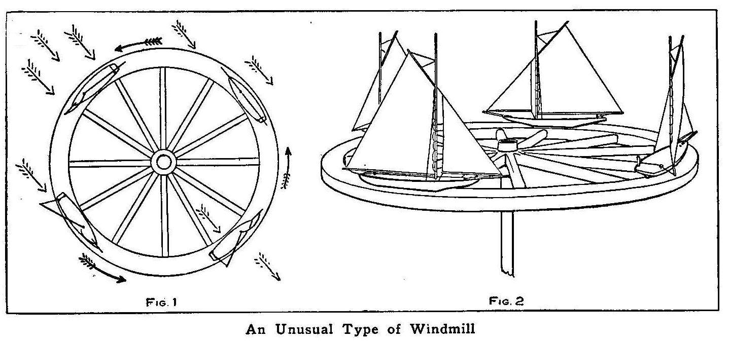
An Unusual Type of Windmill
A novel windmill or revolving wheel can be made by placing a
light wheel so it will turn freely on the end of a post, and
placing four small sailing boats at equal points on the rim of
the wheel. It makes no difference which way the wind blows, the
wheel will revolve in one direction. In Fig. 1 the direction of
the wind is shown by the arrows, and how the sails catch the wind
and cause the wheel to revolve. Figure 2 shows how the wheel will
appear when complete. This device makes an attractive advertising
sign.
A Floating Electromagnet
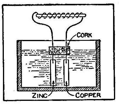
A piece of iron placed in a coil of wire carrying a current of
electricity becomes an electromagnet. If such a coil and iron
core be made small enough they can be attached to a cork and the
cork, floating on a solution, will allow the magnet to point
north and south. The sketch shows how to make such an instrument.
A coil of insulated wire is wrapped around a small iron core,
leaving a few inches of each end free for connections. The
insulation is removed from these ends and they are run through a
piece of cork. Attach to the wires, on the under side of the
cork, a piece of zinc to one end and a piece of copper to the
other. The cork is then floated on a solution of acid, with the
zinc and copper hanging in the solution. If zinc and copper are
used, the solution is made from water and blue vitriol. If zinc
and carbon are used, the solution is made from sal ammoniac and
water.
The float will move about on the solution until the magnet iron
will point north and south. If two of them are floating on the
same solution, they will move about and finally arrange
themselves end to end with the coils and magnet cores pointing
north and south.
Contributed by C. Lloyd Enos.
A Fish Bait
A very effective fish bait is made by inclosing a live minnow in
a short section of glass tube, which is filled with water and
both ends closed with corks. This is used in place of the spoon.
Homemade Air Thermometer
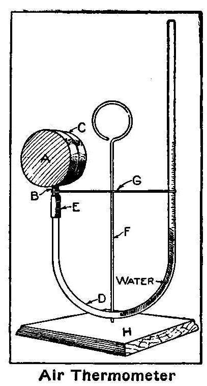
Air Thermometer
The illustration shows the complete thermometer. The water in the
glass tube is caused to rise and fall by the expansion and
contraction of the air in the tin box.
A paper-fastener box, about 1-1/4 in. deep and 2 in. in diameter
will serve very well for the box A. Solder in the side of the box
1-in. piece of 1/4-in. brass tubing, B, and then solder on the
cover, C, so that the only escape for the air is through the
brass tube. Secure a piece of 1/4-in. glass tubing—not shorter
than 18 in.—and bend it as shown at D in the sketch. Hold the
part of the tube to be bent in the broad side of a gas jet, and
in a minute or two the tube will bend with its own weight. Any
angle can be given glass tubing in this way. Connect the glass
tube to B with a short piece of rubber hose, E. If the hose is
not a tight fit, bind with a short piece of fine copper wire. The
standard, F, is made from a piece of No. 10 wire about 10 in.
long. To this standard solder the supporting wire, G—No. 14 wire
will do. On one side bend the wire around the tube B, and on the
other around the glass tube, D.
The base, H, can be made of oak, stained and varnished. The
bottom of the box, A, is covered with lampblack so as to readily
absorb all heat that strikes the surface. The black should not be
put on until just before you paint the supports, cover and rim of
the box with gold or silver paint. Hold the bottom of the box to
be blackened over a little burning cotton saturated with
turpentine.
The scale on the glass can be etched with
hydrofluoric acid, or
made with a little black paint. The water can be put in with a
medicine dropper. This instrument will measure the amount of heat
given by a candle some 20 or 30 ft. away.
Contributed by J. Thos. Rhamstine.
Home-Made Battery Voltmeter
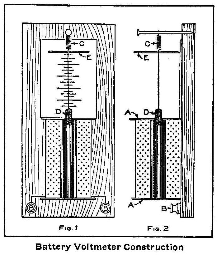
Battery Voltmeter Construction
Secure a piece of brass tube 3 in. long that has about 1/4-in.
hole. Put ends, A, 1-1/4 in. square and cut from heavy cardboard
on this tube. Make a hole in the center of each cardboard just
large enough to allow the brass tube to fit tight. Put on two or
three layers of stout paper around the brass tube and between the
cardboard ends. Wind evenly about 2 oz. of No. 26 cotton covered
magnet wire on the paper between the ends and leave about 2 in.
of wire on each end extending from the coil. Use a board 1/2-in.
thick, 3 in. wide and 6 in. long for the base and fasten the coil
to it, as shown in Fig. 1. Bore holes for binding-posts, B, one
on each side of the board, and connect the two wires from the
coil to them. At the other end of the board and in the center
drive a wire nail and attach a small spring, C, to it. The spring
should be about 1 in. long. Take a small piece of soft iron, D,
1/2-in. long and just large enough to slip freely through the
brass tube and solder a piece of copper wire to it; the other end
of the copper wire being hooked to the spring, C. The copper wire
must be just long enough to allow the piece of iron, D, to hang
part way in the end of the coil and still hold the spring in
place. A circular piece of cardboard, E, is slipped over the
spring to where the spring joins the wire. This cardboard is to
serve as the pointer. A piece of paper 1-1/2 in. wide and 2-1/2
in. long is glued to the board so that it will be directly under
the cardboard pointer and fit snugly up against the top of the
coil.
The paper can be calibrated by connecting one cell of battery to
the binding-posts. The iron plunger, D, is drawn into the tube
and consequently the pointer, E, is drawn nearer to the coil.
Make a mark directly under the place where the pointer comes to
rest. At the place mark the number of volts the cell reads when
connected with a voltmeter. Do the same with two or three cells
and mark down the result on the scale. By dividing off the space
between these marks you may be able to obtain a surprisingly
correct reading when connected with the battery cells to be
tested.
Contributed by Edward M. Teasdale, Cuba, N. Y.
How to Make a Folding Canvas Cot
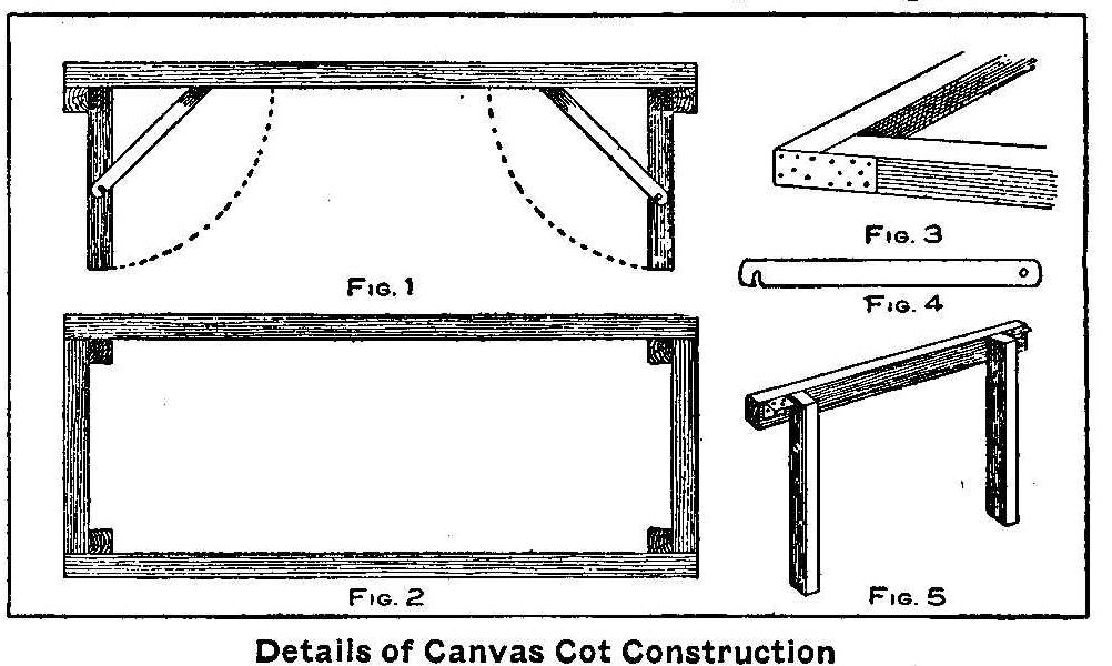
Details of Canvas Cot Construction
All the material required to make the cot as shown in Fig. 1
consists of wood 1-1/2 in. square of which two pieces are 6 ft.
long; two pieces 2 ft. 3 in. long; two pieces 2-1/2 ft. long;
four pieces 1-1/2 ft. long; four hinges; some sheet metal and
2-1/4 yd. of 8-oz. canvas.
Make a rectangle of the two long pieces and the two 2-ft. 3-in.
pieces of wood as shown in Fig. 2, nailing well the corners
together and reinforcing with a strip of sheet metal as shown in
Fig. 3. The four pieces 1-1/2 ft. long are used for the legs, and
two of them are nailed to one of the pieces 2-1/2 ft. long,
making a support as shown in Fig. 5.
Make two of these—one for each end. The hinges are attached as
shown in Fig. 5 and the whole support is fastened just under the
end pieces of the frame by hinges. Four pieces of sheet metal are
cut as shown in Fig. 4 and fastened to the body of the frame with
their lower ends hooking over pins driven in each leg at the
proper place. The canvas is stretched as tight as possible over
the two long side pieces and fastened on the outside edge of each
piece with large headed tacks. The legs will fold up as shown by
the dotted line and the cot can be stored in a small
space.
Contributed by R. J. Smith, Milwaukee, Wis.
How to Make a Small Geissler Tube
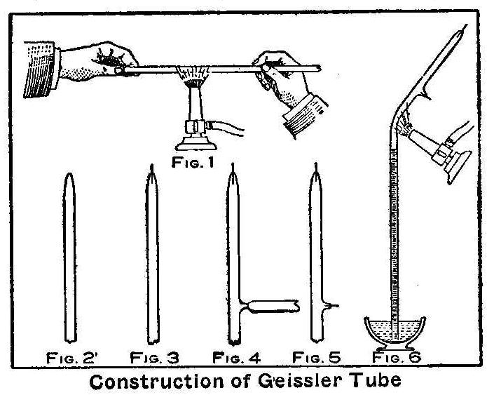
Construction of Geissler Tube
At first this would seem to be a difficult piece of work, yet a
good and beautiful Geissler tube can be made at home in the
following manner:
Procure a glass tube about 3-1/2 ft. long having a hole through
its center about 1/8 or 1/4 in. in diameter, about 1 in. of No.
30 platinum wire and enough
mercury to fill the tube and a small
bowl. About 1-1/2 lb. of
mercury will be sufficient. The first
thing to do is to seal 1/2 in. of platinum wire in one end of the
tube. This is done by holding the end of the tube with the right
hand and taking hold of the tube with the left hand about 4 in.
from the right hand. Hold the tube in a flame of a bunsen burner
in such manner that the flame will strike the tube midway between
the hands, as shown in Fig. 1, and keep turning the tube so as to
get an even heat. When the glass becomes soft, remove the tube
from the flame and quickly draw it out into a fine thread. Break
this thread off about 1/8 in. from the long part of the tube and
the end will appear as shown in Fig. 2. Take 1/2 in. of the
platinum wire and slip it through the fine hole made by breaking
the glass thread so that one-half of the wire will be inside of
the long tube. If the end of the tube is now placed in the flame
of the burner, the glass will adhere to the platinum wire and the
wire will thus be sealed in the tube. The finished end will
appear as shown in Fig. 3. This tube as described will be 8 in.
long, although nearly any size could be made in the same way.
Measure 8 in. from the sealed end and place the tube at that
point in the flame, holding in the left hand. At the same time
take the piece of glass that was broken off at the end in the
first operation and hold it in the flame with the right hand.
When both the tube and piece of glass are soft, touch the soft
part of the tube with the end of the glass and draw the tube out
into a point like that shown in Fig. 4. Break off the piece of
glass, thus leaving a small aperture in the long tube. Seal the
remaining 1/2 in. of platinum in this aperture in the same manner
as before being careful not to heat the tube too suddenly. The
tube is now ready for filling and the upper part will appear as
shown in Fig. 5.
The air is expelled from the tube by filling with
mercury. This
may be done by making a paper funnel and pouring the
mercury
slowly into the tube through the funnel. When the tube is filled
to within 1/2 in. of the funnel remove the funnel and tap the
side of the tube gently in order to remove any small air bubbles
that may be clinging to the sides of the tube. The air bubbles
will rise and come to the top. The tube now must be filled
completely, expelling all the air. Place a finger over the end of
the tube to keep the mercury
in and invert the tube and set the
end in the bowl of mercury.
The mercury in the tube will sink
until the level will be at about 30 in., leaving 8 in. of vacuum
at the top. The next operation is to seal the tube at the
half-way point between the lower platinum wire and the
mercury
level.
As the lower end of the tube must be kept at all times in the
bowl of mercury until
the tube is sealed, an assistant will be
necessary for this last operation. Have the assistant hold the
tube in the mercury
at a slight angle, using care to always keep
the lower end in the mercury,
while you hold the burner in the
left hand and allow the flame to strike the tube at the stated
point. The part of the tube above this point will gradually bend
over of its own weight as the glass softens. When it reaches the
angle of about 60 deg., Fig. 6, take hold of the tube with the
right hand still keeping the flame on the tube, and gradually
draw the softened portion out until it separates from the main
tube.
The tube is now finished and when the platinum wires are attached
to the terminals of a spark coil a beautiful blue light will
appear in the tube with a dark space at the negative end or
cathode.
Contributed by David A. Keys, Toronto, Can.
Loosening Rusted Nuts
Nuts that are rusted fast can often be loosened by giving a hard
turn in the tightening direction.
Cleaning Greasy Stoves
Greasy stoves may be cleaned with a strong solution of
lye or
soda.
How to Make a Take-Down Background Frame
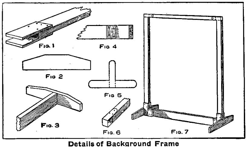
Fig.6—Details of Background Frame
Many amateur photographers who desire to do portrait work at home
have left the subject alone for the want of a suitable
background. A frame such as is used by the professional is
entirely out of the question in most homes, says a correspondent
of Camera Craft. The frame as shown in the sketch was devised and
its chief advantage lies in the fact that when not in use it can
be compactly tied together and stored away in a closet.
Almost any wood may be used in constructing this frame, but
yellow pine is the best, as it is easily obtained and at the same
time very well suited for such work. All pieces are to be dressed
on all sides.
Two upright pieces are cut from 3/4 in. material 2 in. wide and 5
ft. 9 in. long and two blocks are fastened on the ends of each
that are to be used for the bottom, as shown in Fig. 1. These
blocks are each 2 by 6-in. and 1/4 in. thick. The base is made
from a piece 3/4 in. thick, 3 in. wide and 5 ft. 4 in. long. A
crosspiece 3/4-in. thick, 3 in. wide and 12 in. long, cut in the
shape shown in Fig. 2, is screwed on each end of the base with
3-in. wood screws, as shown in Fig. 3. Four blocks 1/4 in. thick,
1 in. wide and 3 in. long are nailed to the sides of the base
piece parallel with and at a distance of 2 in. from the end of
same. This forms a slot, Fig. 4, to receive the pieces nailed to
the ends of the uprights. To secure a rigid frame it is essential
that this, joint be accurately put together.
Procure a piece of thick tin or brass and make two pieces like
the pattern shown in Fig. 5, with each projection 3-in. long. The
width of the crosspiece is 1 in. and the single projection 3/4
in. These are bent and nailed, one on each end of a piece of wood
that is 1/4 in. thick, 1 in. wide and 5 ft. long, as in Fig. 6.
These will form two pockets that will fit over the tops of the
uprights. The frame is put together as shown in Fig. 7. Any
background that will hang straight without need of being
stretched can be hung on this frame.
Home-Made Kite Reel
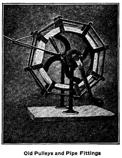
Old Pulleys and Pipe Fittings
This kite reel is constructed from two old pulleys and a few pipe
fittings. The large pulley is about 14 in. in diameter, on the
face of which are riveted flat strips of iron with extending
arms. These arms are reinforced by riveting smaller pieces from
one to the other, which connects all arms together on both sides
of the wheel. Mounted on the shaft with the pulleys is a guide
for the kite wire or string. The photograph shows that this guide
permits of being moved entirely over the top of the reel. The
smaller pulley is attached to the shaft and used as a brake. The
brake is used only when running out the wire or string, first
removing the crank.
Attaching Runners to a Bicycle for Winter Use
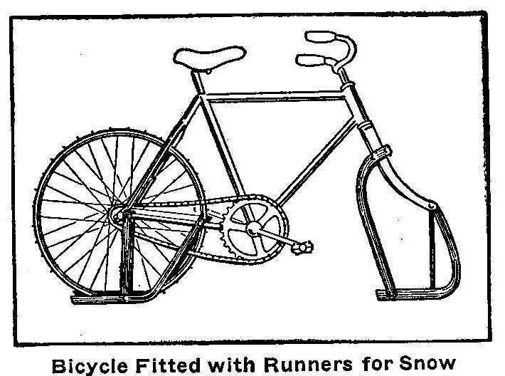
Bicycle Fitted with Runners for Snow
Instead of storing away your bicycle for the winter, attach
runners and use it on the ice. The runners can be made from
1/4-in. by 1-in. iron and fastened to the bicycle frame as shown
in the sketch. The tire is removed from the rim of the rear wheel
and large screws turned into the rim, leaving the greater part of
the screw extending. Cut off the heads of the screws and file
them to a point. The rear runners should be set so the rim of the
wheel will be about 1/2 in. above the runner level.
Contributed by C. R. Welsh, Manhattan, Kan.
A Paper That Makes Green Prints
A coating for ordinary paper that is said to give green prints is
made with a two per cent solution of gelatine, says Photography,
and sensitized with the following solution:
| Potassium Bichromate | 15 gr. |
| Magnesium Sulphate | 15 gr. |
| Water | 1 oz. |
This mixture is spread over the paper in the usual way and the
paper dried in the dark. Printing is carried rather far. The
print is washed, then surface dried or blotted off on a pad and
laid film upwards on a sheet of glass, and the following
developer is applied with a wad of cotton wool wrung out:
| Pyrocatechin | 5 gr. |
| Water | 1 oz. |
The picture assumes a rich green color when developed, and is
then washed for five or ten minutes and dried quickly by heat.
Copies Made from Wax Molds by Electro-Deposition
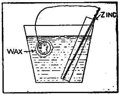
Fine copies of wax impressions can be made in the following
manner: Procure an ordinary tumbler and fill it with a strong
solution of sulphate of copper, which is made by dissolving two
cents’ worth of blue vitriol in 1/2 pt. of water. After this is
done make a porous cell by rolling a piece of brown paper around
a stick and fastening the edge with sealing wax; also, fix a
bottom to the cell in the same way. Make a solution of one part
of oil of vitriol [sulfuric acid]
and 5 parts of water and pour this mixture into
the porous cell. Wind the end of a copper wire around the end of
a piece of zinc and place the zinc in the porous cell. Attach the
other end of the wire to the wax impression.
The wax impression is made by pouring melted beeswax on the
article you wish to reproduce and removing after the wax gets
cold. The wax mold then should be coated with black
lead and
polished. This is done with a camel’s hair brush. A fine copy can
be made on the wax impression after the battery has been running
about 12 hr.
Contributed by Edward M. Treasdale.
How to Make Skating Shoes
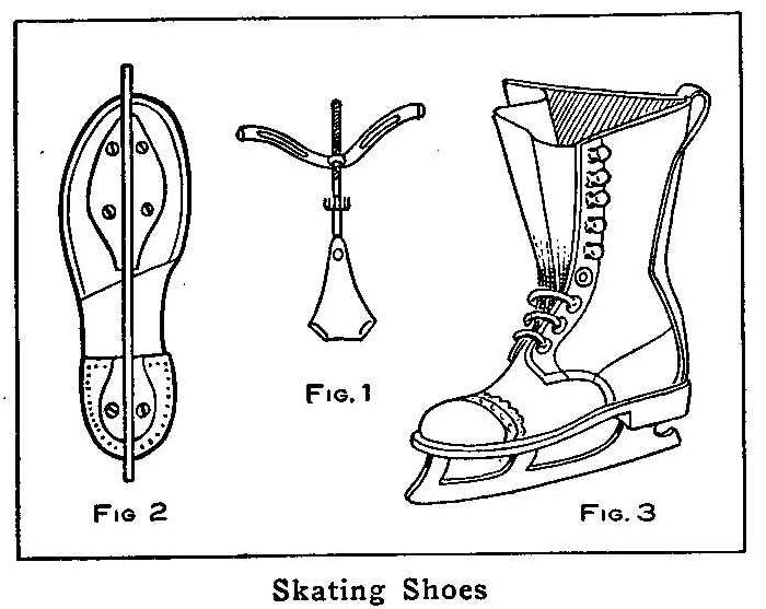
Skating Shoes
Remove the clamp part, as shown in Fig. 1, from an ordinary clamp
skate. Drill holes in the top part of the skate for screws.
Purchase a pair of high shoes with heavy soles and fasten the
skates to the soles with screws, as shown in Fig. 2. When
completed the skating shoes will have the appearance shown on
Fig. 3. These will make as good skating shoes as can be
purchased, and very much cheaper.
Contributed by Wallace C. Newton, Leominster, Mass.
How to Make a Self-Setting Rabbit Trap
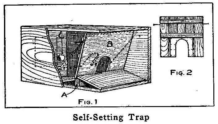
Self-Setting Trap
Secure a good-sized box, say, 1 ft. high, 1-1/2 ft. wide, and 3
ft. long; and to the bottom, about 10 in. from one end, fasten a
2-in. square piece, A, Fig. 1, extending the width of the box.
Place a 10-in. board sloping from the end of the box to the cleat
A. The swing door B, Fig. 1, is made as shown in Fig. 2, which
represents the back side of the door. Sheet metal or tin is cut
to the proper size and tacked around the edge of the hole. This
prevents the animal from gnawing its way out, also provides a way
to make the hole of different sizes for squirrels or other
animals. The hole in the door should be about 2 in. wide and 4
in. high for rabbits. The door is made to swing freely on two
large nails driven through the sides of the box. The hole in the
door being only large enough to admit a small portion of the
rabbit’s head, the rabbit will push its way through to the bait,
causing the door to swing back and up, and it will close by its
own weight when the animal is inside. A small door is provided in
the other end to remove the animals caught.
The advantage of this trap is that where one animal is caught
others are liable to follow, and several rabbits will be trapped
at a time. Then, too, the rabbits are not harmed in any way as
they would be if caught in an ordinary trap.
Contributed by H. F. Church, Alexandria, Va.
How to Make an Atomizer
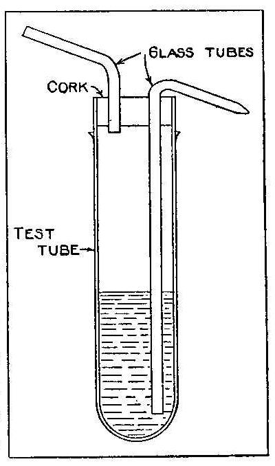
Secure a good-sized test tube and fit it with a cork. Take two
glass tubes, with about 1/8-in. hole, and bend them as shown in
the sketch. This is done by heating them at the proper point over
a gas flame until they are soft. Two holes are bored through the
cork and the bent tubes inserted in them, as shown in the sketch,
so that one of the tubes will extend nearly to the bottom of the
test tube and the other just projecting through the cork. The
spray tube may be made with a fine hole by first securing a tube
longer than necessary and heating it at the proper point and
drawing the tube out into a fine thread. The thread is broken off
at the proper place to make a small hole.
Home-Made Kits for the Camera
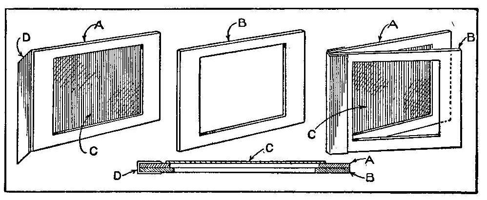
If you have a 5 by 7-in. camera and wish to use some 4 by 5-in.
plates, make a few simple kits to hold the smaller plates and fit
the larger holders, says Camera Craft. Take two pieces of
pasteboard, A and B, black surfaced if possible, and exactly 5 by
7 in. in size. The piece A will form the back of the kit and
should have an opening cut in the center 4 by 5 in. in size.
Paste a piece of strong black paper, C, over the under side of it
to keep the plate from falling through. Cut an opening in the
other piece, B, but cut it 1/4 in. shorter. This opening, being
1/8 in. shorter at each end, will retain the plate in position
and cut off only that small amount of plate surface when the
plate is exposed in the camera. Cut a piece of thin black cloth,
D, 1 in. wide and 5 in. long. Lay it down on a piece of newspaper
and coat one side with gum or mucilage. Stand the two pieces of 5
by 7 in. black cards on end together so that they will be square
and true and bind the other ends with the strip of cloth so as to
form a hinge. The two cards form a thickness about equal to a
thick glass plate, and go in the holder in the same way. Lay one
of these kits down against the ground side of the focusing screen
and draw a line around, inside of the opening. This will be a
guide as to just what will be secured upon the smaller plate when
the kits are used.
How to Make a Miniature Stage
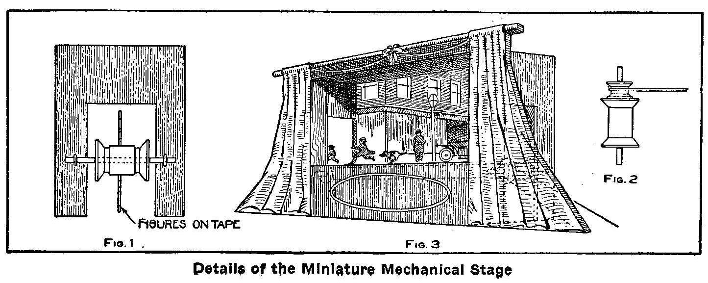
A good smooth box, say 8 in. wide, 10 in. high and 12 in. long,
will serve the purpose for the main part of this small theater.
Cut two rectangular holes, Fig. 1, one in each end and exactly
opposite each other. Place a screw eye about 1/2 in. from the
edge on each side of these openings. Fit an axle in the screw
eyes and fasten a spool to the middle of the axle. On one of the
two spools attach another smaller spool, Fig. 2, to be used as a
driving pulley. Cut out the front part of the box down to a level
with the top of the spools. Connect the spools with a belt made
from tape about 3/4 in. wide. On this belt fasten figures cut
from heavy paper and made in the form of people, automobiles,
trolley cars, horses and dogs. A painted scenery can be made in
behind the movable tape. The front part of the box may be draped
with curtains, making the appearance of the ordinary stage, as
shown in Fig. 3. A small motor will run the spools and drive the
tape on which the figures are attached.
Contributed by William M. Crilly, Jr., Chicago.
A Floating Compass Needle
When a thoroughly dry and clean sewing needle is carefully placed
on the surface of water the needle will float even if the density
of steel is 7 or 8 times that of water. A sewing needle thus
floating upon water may be used as a compass, if it has
previously been magnetized. The needle will then point north and
south, and will maintain this position if the containing vessel
is moved about; if the needle is displaced by force it will
return to its position along the magnetic meridian as soon as the
restraint is removed.
Home-Made Dog Cart
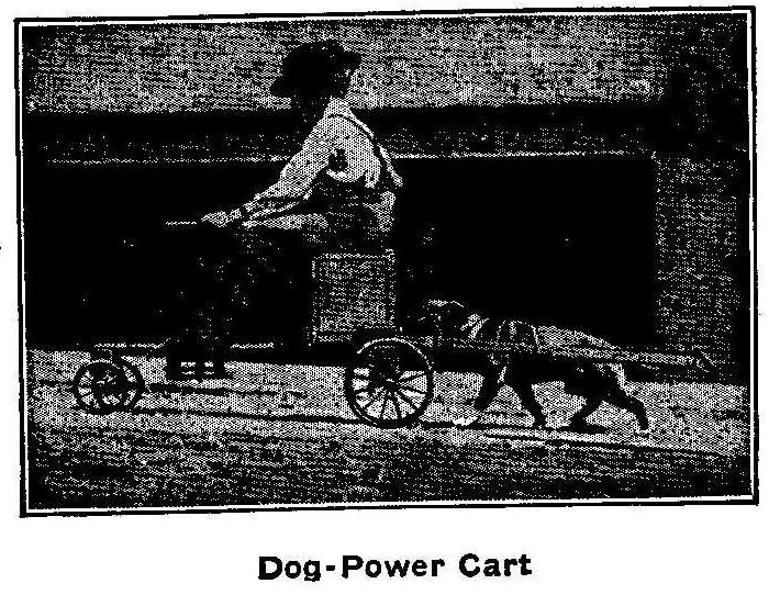
Dog-Power Cart
The accompanying photograph shows a boy with his “dogmobile.” The
photograph was taken when they were on a new pavement which had 2
in. of sand left by the pavers and a grade of 6 per cent. The
machine is nothing more than a boy’s rubber-tired wagon on which
are mounted a box for a seat and a wheel steering device
extending above and below the board of the wagon. The front
wheels are guided by ropes attached from each end of the axle and
a few turns around the lower end of the steering rod. A pair of
shafts are attached to the rear, into which the dog is harnessed.
How to Make a Dry Battery Cell
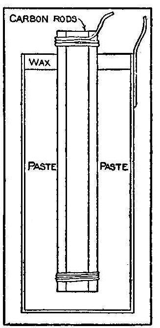
Dry battery cells are composed of the same materials for the
poles, but instead of the liquid commonly used a paste is formed
by mixing sal ammoniac and other salts with water and packed in
the cell so it cannot spill.
A cell of this kind can easily be made, and to make it the proper
size a sheet of zinc 8-1/2 in. long and 6 in. wide will be
required. This zinc is rolled into a cylinder 2-1/2-in. in
diameter. This will allow for a lap of 5/8 in., which is tightly
soldered only on the outside of the seam. Close one end of the
cylinder by soldering a disk of zinc over it, making a watertight
receptacle. All soldering should be done on the outside and none
of the solder allowed to run on the inside of the seam. All seams
on the inside should be painted with asphaltum in order to cover
any particles of solder. Do not paint any surface, only the
joints. Secure three carbon rods 1/2-in. in diameter and 6 in.
long which are copper plated. Carbons used in arc lamps will do.
File the rods to remove the copper plate, leaving about 1/2-in.
of the plate at one end. Tie the three rods in a close bundle
with the copper-plated ends together and make a contact with each
rod by soldering a wire to the plated ends, allowing one end of
the wire to project about 2 in. for a connection. The plated ends
of the carbons should be covered with paraffin for about 1 in.
This is done by immersing them in a dish of smoking hot melted
paraffin until the pores are thoroughly saturated.
The salts for filling are 1/4 lb. zinc oxide, 1/4 lb. sal ammoniac,
3/4 lb. plaster of paris, 1/4 lb. chloride of zinc mixed into a
paste by adding 1/2 pt. of water. Form a 1/2-in. layer of paste
in the bottom of the cylinder and place the ends of the carbon
rods on this with their plated ends up. Hold the rods in the
center of the cylinder and put the paste in around the rods with
a stick. Pack the paste in, closely filling the cylinder to
within 3/4 in. of the top. This space at the top is filled with a
mixture of 1/2 lb. of rosin and 2 oz. beeswax melted together.
This wax seals the cell and prevents any evaporation. Connection
is made to the zinc by soldering a wire to the outside of the
cylinder.
How to Paraffin Wire
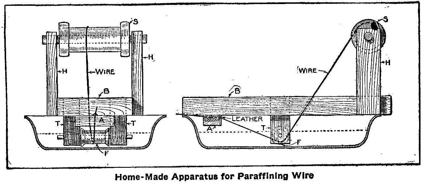
Home-Made Apparatus for Paraffining Wire
The following description of how to make an apparatus with which
to paraffin wire as needed makes clear a method of construction
that is simple and easy to put together in a short time. Secure
a pan to be used for this purpose only; one that will hold about
1 qt. The details of the construction are given in the diagram,
in which P is the pan; B is a base of 1 in. pine; S is the spool
of wire supported near one end of the base by nailing on
standards H and H; F is a spool, with narrow flanges, supported
near the bottom of the pan by the standards T and T. These may be
made of two short pieces of a roller fitted into the holes bored
in the base; A is a block of 1-in. pine with a piece of leather
tacked on one side. Four nails should be driven in the base just
outside of the edge of the pan to keep it from sliding off the
pan.
Bore a hole in the base between the two spools and pass the wire
through this hole, under the spool in the paraffin, then through
a small hole in the leather and a notch in the block A, and a
notch between the base and the pan. Tie a string around the wire
between the leather and the paraffin, making the knots so they
will not pull through the hole in the leather. This makes the
wire smooth, and by making the string tighter or looser you can
regulate the thickness of the paraffin, says Electrician and
Mechanic. Place the pan on the stove; when the paraffin is
melted, pull out the wire as needed. To keep the pan from sliding
place a flatiron or some other weight on it.
Uses of Peat
Peat is used in Germany for bedding, fodder, filter, fuel and
packing purposes.
Scientific Explanation of a Toy
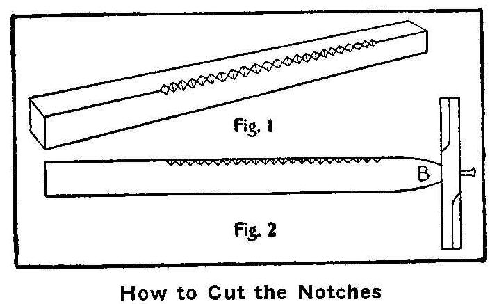
How to Cut the Notches
In a recent Issue of Popular Mechanics an article on “The Turning
Card Puzzle” was described and illustrated. Outside of the
scientific side involved herein I describe a much better trick.
About the time when the expression “skidoo” first began to be
used I invented the following trick and called it “Skidoo” and
“Skidee,” which created much merriment. Unless the trick is
thoroughly understood, for some it will turn one way, for others
the opposite way, while for others it will not revolve at all.
One person whom I now recall became red in the face by shouting
skidoo and skidee at it, but the thing would not move at all, and
he finally, from vexation, threw the trick into the fire and a
new one had to be made. Very few can make it turn both ways at
will, and therein is the trick.
Take a piece of hardwood 3/8-in. square and about 9 in. long. On
one of the edges cut a series of notches as indicated in Fig 1.
Then slightly taper the end marked B until it is nicely rounded
as shown in Fig. 2. Next make an arm of a two-arm windmill such
as boys make. Make a hole through the center of this one arm.
Enlarge the hole slightly, enough to allow a common pin to hold
the arm to the end B and not interfere with the revolving arm.
Two or three of these arms may have to be made before one is
secured that is of the exact proportions to catch the vibrations
right.
To operate the trick, grip the stick firmly in one hand, and with
the forward and backward motion of the other allow the first
finger to slide along the top edge, the second finger along the
side and the thumb nail will then vibrate along the notches, thus
making the arm revolve in one direction. To make the arm revolve
in the opposite direction—keep the hand moving all the time, so
the observer will not detect the change which the band
makes—allow the first finger to slide along the top, as in the
other movement, the thumb and second finger changing places: e.
g., in the first movement you scratch the notches with the thumb
nail while the hand is going from the body, and in the second
movement you scratch the notches with the nail of the second
finger when the hand is coming toward the body, thus producing
two different vibrations. In order to make it work perfectly (?)
you must of course say “skidoo” when you begin the first
movement, and then, no matter how fast the little arm is
revolving when changed to the second movement, you must say
“skidee” and the arm will immediately stop and begin revolving in
the opposite direction. By using the magic words the little arm
will obey your commands instantly and your audience will be
mystified. If any of your audience presume to dispute, or think
they can do the same, let them try it. You will no doubt be
accused of blowing or drawing in your breath, and many other
things in order to make the arm operate. At least it is amusing.
Try it and see.
Contributed by Charles Clement Bradley, Toledo, Ohio.
The foregoing article describing the “Skidoo-Skidee Trick”
appeared in a recent issue of Popular Mechanics. I have been told
that a similar arrangement is used by a tribe of Indians in the
state of Washington, by the Hindoos in India, and one friend
tells me that they were sold on the streets of our large cities
many years ago.
This toy interested me so much that I have made an investigation
into the causes of its action, and I think the results may be of
interest.
To operate, one end of the notched stick is held firmly in the
left hand, while with the right hand a nail or match stick is
rubbed along the notched edge, at the same time pressing with the
thumb or finger of the moving hand against the oblique face of
the stick. The direction of rotation depends upon which face is
pressed. A square stick with notches on edge is best, but the
section may be circular or even irregular in shape.
The experiments were as follows:
1. A rectangular stick had notches cut on one face. When the
pressure was applied upon a face normal to the first, no rotation
resulted. If the pressure was upon an edge, rotation was
obtained.
2. Irregular spacing of the notches did not interfere
with the action. The depth of the notches was also unimportant,
although it should be suited to the size of the nail for best
results.
3. The hole in the revolving piece must be larger than the pin;
if there is a close fit no rotation is obtained.
4. The center of gravity of the revolving piece must lie within
the hole. If the hole is not well centered the trick cannot be
performed.
5. If the stick be clamped in a vise no results are obtained;
with this exception: if the stick has enough spring, and the end
clamped is far enough away from the notched portion, the rotation
may be obtained.
The above experiments led me to the conclusion that the operation
of the device is dependent upon a circular motion of the pin, and
this was confirmed by the following experiments. The action is
somewhat similar to swinging the toy known as a locust around
with a slight circular motion of the hand, It is necessary to
show here that a slight circular motion is sufficient to produce
the result and, secondly, that such motion can be produced by the
given movements of the hands.
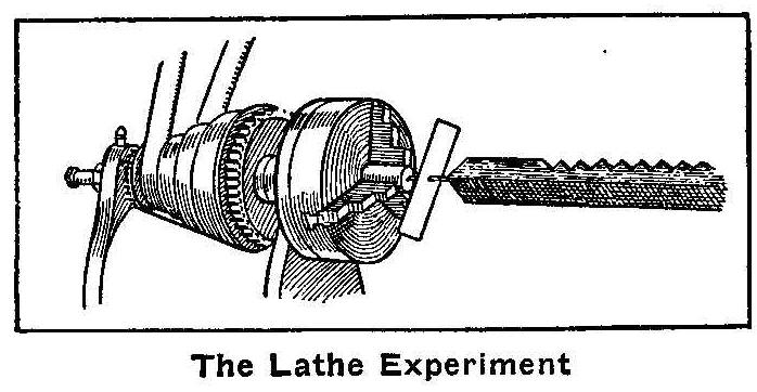
The Lathe Experiment
6. A piece of brass rod was clamped in the chuck of a lathe, and
a depression made in the end slightly eccentric, by means of a
center punch. If the end of the pin is inserted in this
depression, while the hand holding the other end of the stick is
kept as nearly as possible in the axis of the lathe, rotation of
the lathe will produce rotation of the revolving piece. Speeds
between 700 and 1,100 r. p. m. gave the best results.
7. A tiny mirror was attached to the end of the pin, and the hand
held in the sunlight so that a spot of sunlight was reflected
upon the wall. The notches were then rubbed in the usual way. The
spot of light upon the wall moved in a way which disclosed two
components of motion, one circular and one due to the irregular
movements of the hand holding the stick. Usually the orbit was
too irregular to show a continuous and closed circular path, but
at times the circular motion became very pronounced. It was
observed and the direction of rotation correctly stated by a man
who was unaware of the source of the motion.
The production of the circular motion can be explained in this
way: When the rubbing nail comes to a notch the release of
pressure sends the stick upward; this upward motion against the
oblique pressure upon the (say) right hand side gives also a
lateral component of motion towards the left. As the nail strikes
the opposite side of the notch the stick is knocked down again,
this motion relieves somewhat the oblique pressure from the right
hand side, and, the reaction from the holding (left) hand moves
the stick to the right slightly, so that it is back in the old
position for the next upward motion. Thus a circular or elliptic
motion is repeated for each notch, and the direction of this
motion is the same whether the nail be rubbed forward or back.
For oblique side pressure from the right (notches assumed
upward), the motion of the stick and hence of the revolving piece
will be counter-clockwise; if the pressure is from the left, it
will be clockwise.
That the motion of the revolving piece is due to a swinging
action, and not to friction of the pin in the hole, is proved by
experiments 3 and 4.
Contributed by M. G. Lloyd, Ph.D., Washington, D. C.
Home-Made Lantern
Tin Can Lantern
The accompanying picture shows a lantern which can be made almost
anywhere for immediate use. All that is needed is an empty tomato
or coffee can, a piece of wire and a candle. Make a hole a little
smaller than the diameter of a candle and about one-third of the
way from the closed end of the can, as shown. A wire is tied
around the can, forming a handle for carrying. This kind of
lantern can be carried against almost any wind and the light will
not be blown out.
Contributed by G. A. Sloan, Duluth, Minn.
A Study of Splashes
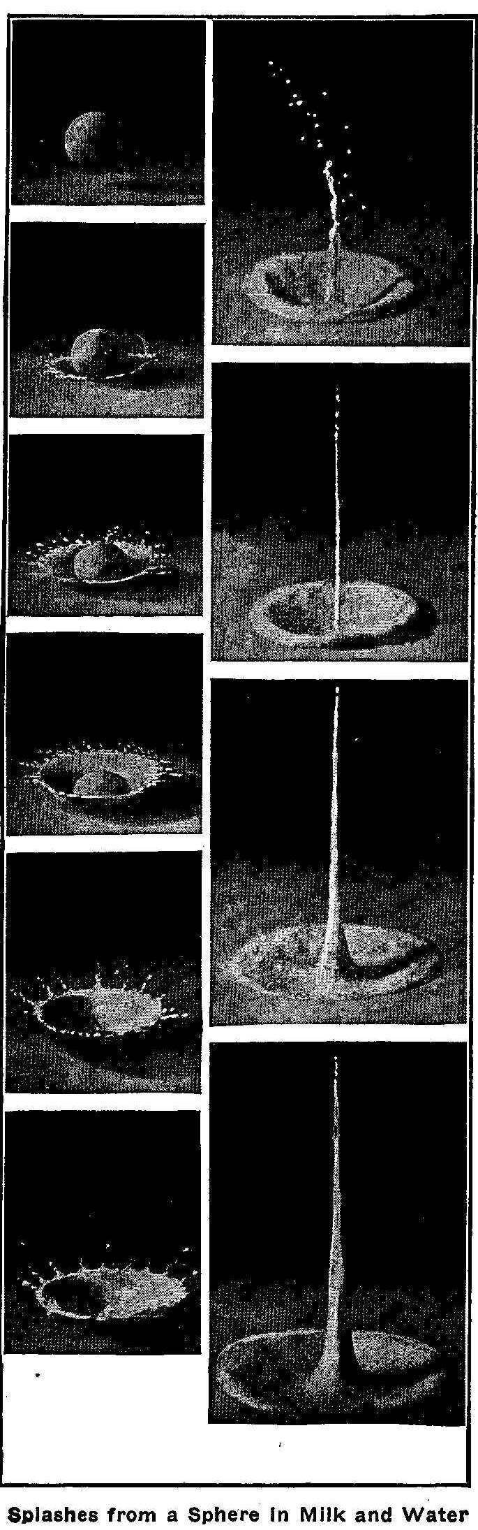
Splashes from a Sphere In Milk and Water
When a rough, or greasy, or dusty sphere falls into a liquid, the
liquid is forced away from the sphere. If the sphere is quite
smooth the liquid rises up around and enclosing it in a sheath
says Knowledge and Scientific News.
Reproduced herewith are a series of photographs showing
successive stages in the entry of a rough sphere into milk and
water, and the resultant “basket splash.” The diameter of this
sphere was about 3/5 in., and the height of the fall about 6 in.
Examination of the photographs shows that the liquid, instead of
flowing over and wetting the surface of the sphere, is driven
violently away, so far as can be seen from the photographs, the
upper portion is, at first, unwetted by the liquid. The gradual
thickening of the crater wall and the corresponding reduction in
the number of its lobes as the subsidence proceeds is beautifully
shown. Thereafter there rises from the depth of the crater an
exquisite jet which in obedience to the law of segmentation at
once splits up in its upper portion into little drops, while at
the same time it gathers volume from below and rises ultimately
as a tall, graceful column to a height which may be even greater
than that from which the sphere fell.
How to Make a Stick Pin
A fine stick pin or button can be made from a new one-cent piece.
Carefully file out all the metal around the Indian head and
slightly round the edges. Solder a pin to the back of the head
when it is to be used for a stick pin. If a collar button base is
soldered to the back of the head instead of the pin it can be
used for a button. These can be gold plated by a jeweler and then
you will have a neat pin or button, or a good emblem for the
Order of Redmen.
How to Make a Miniature Electric Locomotive
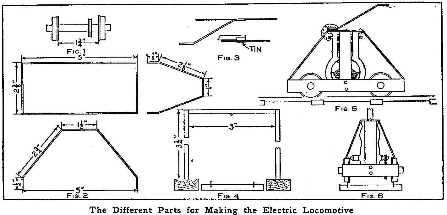
The Different Parts for Making the Electric Locomotive
A miniature electric railway is a thing that attracts the
attention of almost any person. The cost of a toy electric
locomotive is beyond the reach of many boys who could just as
well make such a toy without much expense and be proud to say
they “built it themselves.” The electric locomotive described
herewith uses for its power a small battery motor costing about
$1. The first thing to do is to make the wheels and axles. If one
has no lathe, the wheels can be turned at some machine shop. Four
wheels are made from a round bar of metal, as shown in Fig. 1.
Each wheel is 1/4 in. thick and 1 in. in diameter, with a
1/16-in. flange and a 1/4-in. hole drilled in the center. Each
pair of wheels is fitted on a 1/4-in. axle, about 2-5/8 in. long.
One of the axles should be fitted with a grooved belt wheel, as
shown. Make the frame from three pieces of heavy brass, as shown
in Fig. 2.
The first piece, or main part of the frame, is made from brass,
3/4 in. wide and 16 in. long, bent into an oblong shape and the
ends soldered or bolted together. If the ends are to be soldered,
before doing so drill four 1/4-in. holes 1 in. from the ends and
insert the ends of the axles. The other two pieces are 1/2-in.
wide and of the dimensions shown in the sketch. These pieces are
riveted in the middle of the oblong frame, each in its proper
place. The motor is now bolted, bottom side up, to the top of the
piece fastened to the frame lengthwise. A trolley, Fig. 3, is
made from a piece of clock spring, bent as shown, and a small
piece of tin soldered to the top end for a brush connection. A
groove is made in the tin to keep the trolley wire in place.
The trolley wire is fastened to supports made of wood and of the
dimensions given in Fig. 4. The trolley should be well insulated
from the frame. The parts, put together complete, are shown in
Fig. 5. Run a belt from the pulley on the motor to the grooved
wheel on the axle, as shown in Fig. 6, and the locomotive is
ready for running.
In making the connections the travel of the locomotive may be
made more complicated by placing a rheostat and controlling
switches in the line, so that the engine can be started and
stopped at will from a distance and the speed regulated.
Automatic switches can be attached at the ends of the line to
break the circuit when the locomotive passes a certain point.
One connection from the batteries is made to the trolley wire and
the other to a rail. The connection for the motor runs from one
binding post to the trolley and this connection must be well
insulated to avoid a short-circuit. The other binding-post is
connected to the frame.
The cost of making the wheels and purchasing the track will not
be over $1.50. The track can be made from strips of tin put in a
saw cut made in pieces of wood used for ties. This will save
buying a track.
Contributed by Maurice E. Fuller, San Antonio, Texas.
Demagnetizing a Watch
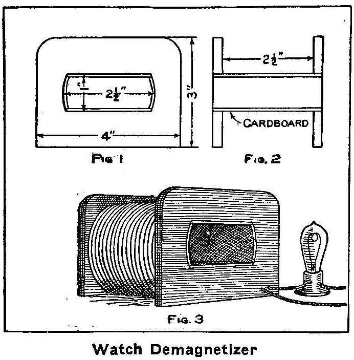
Watch Demagnetizer
A test can be made to know if your watch is magnetized by placing
a small compass on the side of the watch nearest the escapement
wheel if the compass pointer moves with the escapement wheel the
watch is magnetized. A magnetized watch must be placed in a coil
that has an alternating current of electricity flowing through it
to remove the magnetism. A demagnetizer can be made as shown in
the illustration. Two end pieces for the coil are made as shown
in Fig. 1 from 1/4-in. wood. These ends are fastened together,
Fig. 2, with cardboard 3 in. long glued to the inside edges of
the holes cut in them. Wind upon the spool thus formed about 2
lb. of No. 16 cotton-covered copper wire. As it will be necessary
to place a 16-cp. lamp in series with the coil, both the coil and
lamp can be mounted on a suitable base and connected as shown
in Fig. 3. The current, which must be 110 volt alternating
current, is turned on the lamp and coil and the magnetized watch
slowly drawn through the opening in the center of the coil.
Contributed by Arthur Liebenberg, Cincinnati, O.
How to Make a Pocket Skate Sharpener
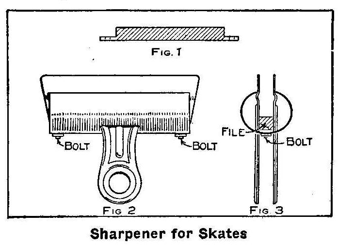
Sharpener for Skates
Secure a square file and break off a piece, Fig 1, the length of
a paper clip, Fig. 2. Draw the temper in the ends of this piece
of file, but do not heat the center. This can be done by wrapping
a wet piece of cloth or asbestos
around the middle and holding it
in the jaws of a pair of tongs which will only leave the end
uncovered and projecting from the tongs about 1/2 in. Hold this
projecting end in a flame of a plumber’s torch until it is a dull
red. Allow this to cool slowly while in the tongs. When cold
treat the other end in the same way. This will draw the temper in
only the ends which are filed, as shown in Fig. 1, and holes
drilled in them. Also drill a hole in each end of the spring on
the paper clip to match those drilled in the piece of file.
Fasten the file in the clip with small bolts, as shown in Fig. 3.
When the file gets filled with filings it can be removed and
cleaned. Place the runner of the skate in the clip and hold flat
on the surface of the runner. If the piece of file is fitted to
the same width as the skate runner the sides of the paper clip
will hold the file level with the surface of the runner without
any trouble. Push the clip back and forth until the skate is
sharpened.
Old-Time Magic
Trick with a Coin in a Wine Glass
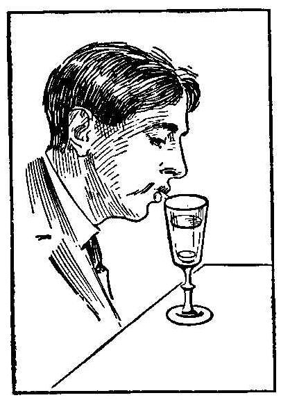
The accompanying sketch shows a trick of removing a dime from
the bottom of an old fashioned wine glass without touching the
coin. The dime is first placed in the bottom of the glass and
then a silver quarter dropped in on top. The quarter will not go
all the way down. Blow hard into the glass in the position shown
and the dime will fly out and strike the blower on the nose.
Untying-a-Knot Trick
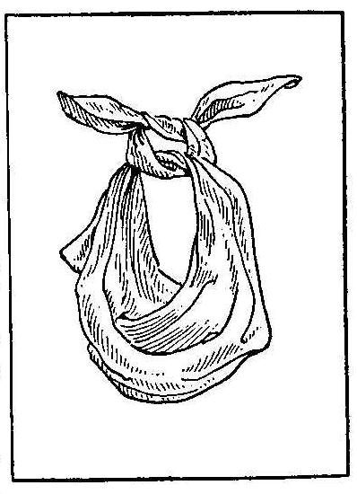
Tie a double knot in a silk handkerchief, as shown in the
accompanying sketch and tighten the last tie a little by slightly
drawing the two upper ends; then continue to tighten much more,
pulling vigorously at the first corner of the handkerchief, and
as this end belongs to the same corner it cannot be pulled much
without loosening the twisted line of the knot to become a
straight line. The other corner forms a slip knot on the end,
which can be drawn out without disturbing the form, or apparent
security of the knot, at the moment when you cover the knot with
the unused part of the handkerchief.
When the trick is to be performed, tie two or three very hard
knots that are tightly drawn and show your audience that they are
not easy to untie. The slip knot as described then must be made
in apparently the same way and untied with the thumb while the
knot is in the folds of the handkerchief.
Gear-Cutting Attachment for Small Lathes
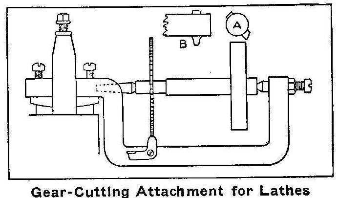
Gear-Cutting Attachment for Lathes
When in need of small gears for experimental or model machines
the amateur usually purchases them, never thinking that he could
make them on his own lathe. A small attachment can be made to
fasten in the tool post of a lathe and the attachment made to
take a mandrel on which to place the blank for cutting a gear.
The frame is made from a 1/2 in. square iron bent as shown in the
sketch with the projecting end filed to fit the tool post of the
lathe. A pair of centers are fitted, one of which should have a
screw thread and lock nut for adjustment in putting in and
removing the mandrel. All the old clock wheels that can be found
should be saved and used for index wheels.
All of these wheels should be fitted to one end of the mandrel.
The blank wheel is put on the outer end of the mandrel and a
clock wheel having the number of teeth desired placed on the
other end. When the mandrel is put in between the centers a small
pawl is fastened with a screw to the frame with its upper end
engaging in a tooth of the clock wheel. One clock wheel will
index more than one number of teeth on a blank wheel. For
instance: if the clock wheel has 18 teeth it can be made to index
6, 9 or 18 teeth to the blank by moving the number of teeth each
time 3, 2 and 1 respectively.
In the sketch, A shows the end of the cutter and B the side and
the shape of the cutting tool. When the cutter A, which is in a
mandrel placed in the centers of the lathe, has finished a cut
for a tooth, the pawl is disengaged and the mandrel turned to
another tooth in the clock wheel.
In order to get the desired height it is sometimes necessary to
block up the lathe head and the final depth of the tooth adjusted
by the two screws in the projecting end of the frame which rests
on the rocker in the tool post. Should too much spring occur when
cutting iron gears the frame can be made rigid by blocking up the
space between it and the lathe bed.
The cutter mandrel is placed in the centers of the lathe, or
should the lathe head be raised, a short mandrel with the cutter
near the end can be placed in a chuck, and adjusted to run true.
The frame holding the mandrel, gear blank and clock wheel is
inserted in the tool post of the lathe and adjusted for depth of
the cutter. The lathe is started and the gear blank fed on the
cutter slowly until the tooth is cut. The pawl is released and
the mandrel turned to the proper number of teeth and the
operation repeated. In this manner gears 3 in. in diameter can be
made on a 6-in. swing lathe.
Contributed by Samuel C. Bunker, Brooklyn, N. Y.
Wire Terminals for Battery Connections
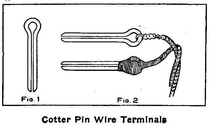
Cotter Pin Wire Terminal.
Good connections on the end of wires for batteries can be made
from cotter pins, Fig. 1, about 1-1/2 in. long. Each end of the
wire is put through the eye of a cotter pin, twisted around
itself and soldered. The connection and eye are then covered
with tape as shown in Fig. 2. When connecting to batteries,
spread the pin and push the parts under the nut with one part on
each side of the binding-post. When the nuts are tightened the
connection will be better than with the bare wire.
Contributed by Howard S. Bott.
Simple Arts and Crafts Leather Work
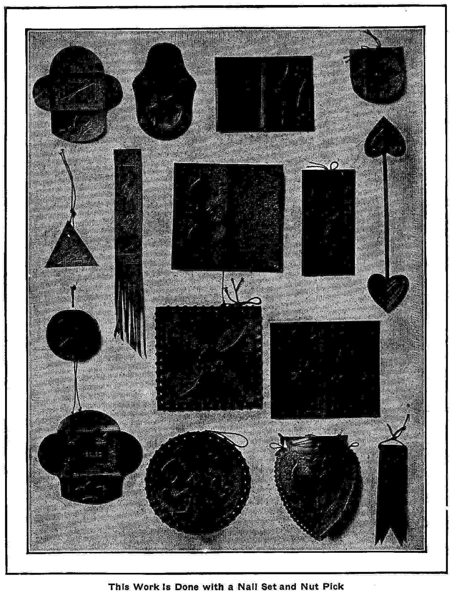
This Work Is Done with a Nail Set and Nut Pick
Very interesting and useful pieces of leather work can be done
with nothing more for equipment than a cup pointed nail set such
as carpenters use, and a nut pick.
The accompanying illustrations show some of the things that can
be made. Beginning at the left and reading to the right they are:
-Case for court-plaster, coin purse, lady’s card case, eye glass
cleaner or pen wiper (has chamois skin within). Second row:—Two
book marks, note book, blotter back, book mark. Third row:—Pin
ball (has saddler’s felt between the two leather disks), tea
cosey, gentleman’s card case or bill book. Fourth row:—Needle or
pin case, tea cosey, lady’s belt bag, watch fob ready for
fastenings.
Procure a piece of Russian calf modeling leather. (1.) Make on
paper the design wanted. (2.) Moisten the back side of the
leather with sponge or cloth with as much water as it will take
yet not show through on the face side. (3.) Place the leather on
some hard non-absorbent material, such as brass or marble. (4.)
Place the paper design on the leather and, holding it in place
with the left hand, trace the outline, of the object and the
decorative design with the nut pick so as to make a V-shaped
groove in the leather. (5.) Take the paper off and working on the
leather directly make the grooves deeper. (6.) With the
cup-pointed nail set stamp the background promiscuously. This is
done by making an effort to hold the point of the set about 1/4
in. above the surface, at the same time striking light, rapid
blows on the top with a hammer or mallet.
With such objects as coin purses and card cases, a sewing machine
will be needed to fasten the parts together. An ordinary machine
will do. Frequently the parts are fastened by punching holes and
lacing through these with leather thongs or silk cord.
In making symmetrical designs such as are here shown, draw center
lines across the required space, dividing it into as many parts
as desired. Make free-hand one quarter of the design, if four
parts are to be alike, or one-half of the design, if but two
parts. Fold over along these center lines. Put a piece of
double-surfaced carbon paper between the parts and trace over the
design already drawn.
How to Make a Simple Still
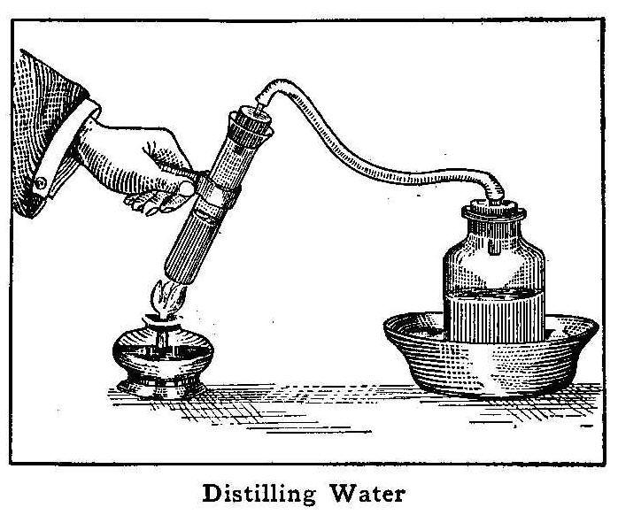
Distilling Water
A still to distill water can be made from a test tube, some heavy
rubber hose, and an ordinary bottle. Secure a stopper for the
test tube, and bore a hole through the center, into which fit a
small piece of tube. The bottle is also fitted with a stopper
containing a piece of tube, and both bottle and test tube
connected with a rubber tube.
The test tube is partly filled with water and supported or held
over an alcohol lamp. The bottle should stand in a basin of cold
water. When the water in the test tube begins to boil the steam
passes over to the bottle, where it condenses. The basin should
be supplied with cold water as fast as it begins to get warm. The
rubber tube will not stand the heat very long and if the still is
to be used several times, a metal tube should be supplied to
connect the test tube and bottle.
Homemade Mariner’s Compass
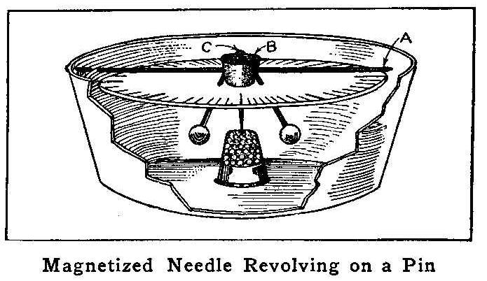
Magnetized Needle Revolving on a Pin
Magnetize an ordinary knitting needle, A, and push it through a
cork, B, and place the cork exactly in the middle of the needle.
Thrust a pin, C, through the cork at right angles to the needle
and stick two sharpened matches in the sides of the cork so that
they will project downward as shown. The whole arrangement is
balanced on a thimble with balls of wax stuck on the heads of the
matches. If the needle is not horizontal, pull it through the
cork to one side or the other, or change the wax balls. The whole
device is placed in a glass berry dish and covered with a pane of
glass.
Brighten White Paint
Add aluminum bronze to a white or light paint that is to be used
for lettering on a dark ground.
Quartz Electrodes Used in Receiving Wireless Messages
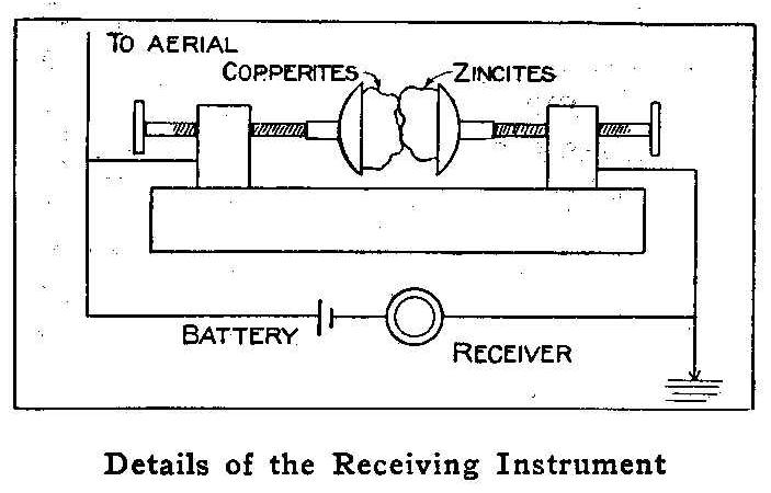
Details of the Receiving Instrument
Wireless messages have been received at Washington, D.C., from
Key West, Florida, a distance of 900 miles, through a receiving
instrument in which two pieces of quartz of different composition
were used on the electrodes. In making an instrument of this kind
the quartz can be purchased from a dealer in minerals. One piece
must contain copper pyrites and the other zincites. The
electrodes are made cupping to hold the minerals and each should
have a screw adjustment to press the pieces of quartz in contact
with each other. Connect as shown in the illustration, using a
high resistance receiver.
Contributed by Edwin L. Powell, Washington, D. C.
How to Make a Glider
By Carl Bates
A gliding machine is a motorless aeroplane, or flying-machine,
propelled by gravity and designed to carry a passenger through
the air from a high point to a lower point some distance away.
Flying in a glider is simply coasting down hill on the air, and
is the most interesting and exciting sport imaginable. The
style of glider described in this article is known as the
“two-surface” or “double-decked” aeroplane, and is composed of
two arched cloth surfaces placed one above the other.
In building a glider the wood material used should be
straight-grained spruce, free from knots. First prepare from
spruce planks the following strips of wood. Four long beams 3/4
in. thick, 1-1/4 in. wide and 20 ft. long; 12 crosspieces 3/4 in.
thick, 3/4 in. wide and 3 ft. long; 12 uprights 1/2 in. thick,
1-1/2 in. wide and 4 ft long; 41 strips for the bent ribs 3/16
in. thick, 1/2-in. wide and 4 ft. long; 2 arm sticks 1 in.
thick, 2 in. wide and 3 ft. long; the rudder sticks 3/4 in.
square and 8 ft long; several strips 1/2 in. by 3/4 in. for
building the vertical and horizontal rudders. The frames for the
two main surfaces should be constructed first, by bolting the
crosspieces to the long beams at the places shown by the
dimensions in Fig. 1. If 20-ft. lumber cannot be procured, use
10-ft. lengths and splice them, as shown in Fig. 3. All bolts
used should be 1/8 in. in diameter and fitted with washers on
both ends. These frames formed by the crosspieces should be
braced by diagonal wires as shown. All wiring is done with No. 16
piano wire.
The 41 ribs may be nailed to the main frames on the upper side by
using fine flat-headed brads 7/8 in. long. These ribs are spaced
1 ft. apart and extend 1 ft. beyond the rear edges of the main
frames, as shown in Fig. 1. After nailing one end of a rib to the
front long beam, the rib is arched by springing down the loose
end and nailing to the rear beam. The ribs should have a curve as
shown in Fig. 2, the amount of curvature being the same in all
the ribs.
The frames of the main surfaces are now ready to be covered with
cloth. Cambric or bleached muslin should be used for the
covering, which is tacked to the front edge, stretched tightly
over the bent ribs and fastened securely with tacks to the rear
ends of the ribs. The cloth should also be glued to the ribs for
safety. In the center of the lower plane surface there should be
an opening 2 ft. wide and 4 ft. long for the body of the
operator. Place the two main surfaces 4 ft. apart and connect
with the 12 uprights, placed in the corner of each crosspiece
and beam. The uprights are fastened by bolting to the
crosspieces, as shown in Fig. 2. The whole structure is made
strong and rigid by bracing with diagonal wires, both laterally
and longitudinally.
The vertical rudder is to keep the machine headed into the wind
and is not movable. This rudder is made of cloth stretched over a
light wooden frame, which is nailed to the rudder sticks
connecting to the main frame. The horizontal rudder is also made
of cloth stretched over a light wooden frame, and arranged to
intersect the vertical rudder at its center. This rudder is held
in position and strengthened by diagonal wires and guy wires. The
horizontal rudder is also immovable and its function is to
prevent the machine from diving, and also to keep it steady in
its flight. The rudders are fastened to the glider by the two
rudder sticks, and these sticks are held rigid by diagonal wires
and also by guy wires leading to the sides of the main frames as
shown in Fig. 1. The two arm sticks should be spaced about 13 in.
apart and bolted to the long beams in the center of the opening
in the lower plane where the operator is to take his position.
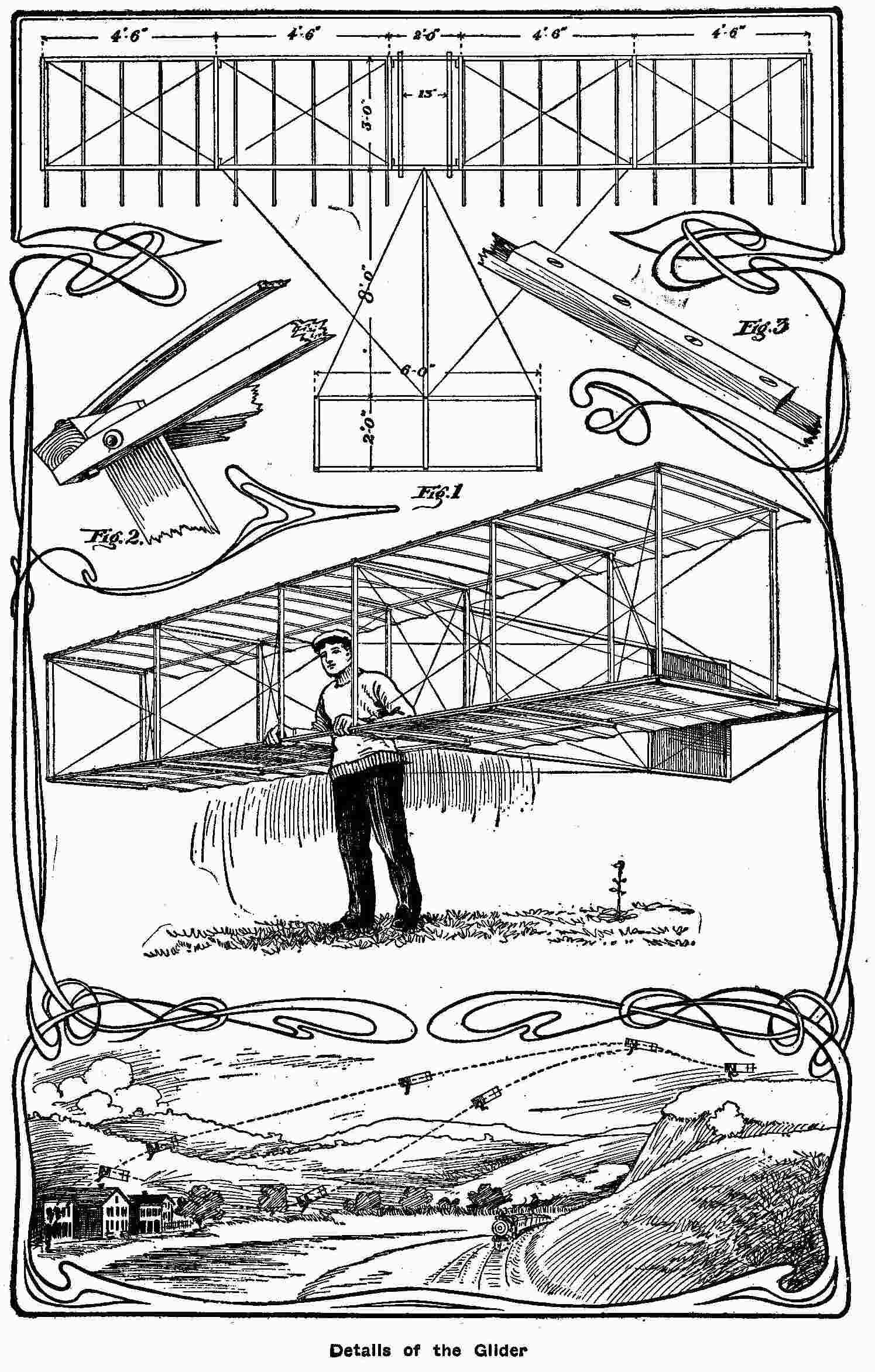
Details of the Glider
The glider should be examined to see that the frame is not warped
or twisted. The surfaces must be true or the machine will be hard
to balance when in flight. To make a glide, take the glider to
the top of a hill, get in between the arm sticks and lift the
machine up until the arm sticks are under the arms as shown run a
few steps against the wind and leap from the ground. You will
find that the machine has a surprising amount of lift, and if the
weight of the body is in the right place you will go shooting
down the hillside in free flight. The landing is made by pushing
the weight of the body backwards. This will cause the glider to
tip up in front, slacken speed and settle. The operator can then
land safely and gently on his feet. Of course, the beginner
should learn by taking short jumps, gradually increasing the
distance as he gains skill and experience in balancing and
landing.
The proper position of the body is slightly ahead of the center
of the planes, but this must be found by experience. The machine
should not be used in winds blowing faster than 15 miles an hour.
Glides are always made against the wind, and the balancing is
done by moving the legs. The higher the starting point the
farther one may fly. Great care should be exercised in making
landings; otherwise the operator might suffer a sprained ankle or
perhaps a broken limb. The illustration shows two lines of flight
from a hilltop, the glider travels on the upper line caused by
the body of the operator taking a position a little back of the
proper place, and on the lower line he changes his position from
front to back while flying, which causes the dip in the line.
Boys Representing the Centaur
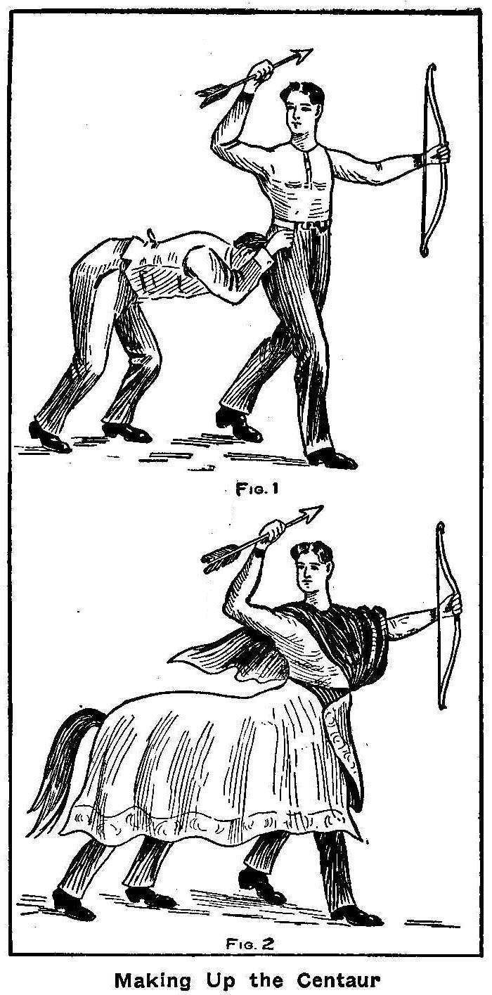
Making Up the Centaur
This is a diversion in which two boys personate a Centaur, a
creature of Greek mythology, half man and half horse. One of the
players stands erect and the other behind him in a stooping
position with his hands upon the first player’s hips, as shown in
Fig. 1. The second player is covered over with a shawl or table
cover which is pinned around the waist of the first player. A
tail made of strips of cloth or paper is pinned to the rear end
of the cover. The first player should hold a bow and arrow and
have a cloak thrown loosely over his shoulder, as shown in Fig.
2. Imitation hoofs of pasteboard may be made and fastened over
the shoes.
Home-Made Ladle for Melting Babbitt
Secure a large sized old bicycle bell and rivet a heavy wire or
strap iron on one side for a handle. When heated a little, hammer
out the edge on one side for a lip to pour from. This makes a
good ladle for melting small amounts of babbit or
lead.
Contributed by L. M. Olson, Bellingham, Wash
How to Make a Flash Lamp
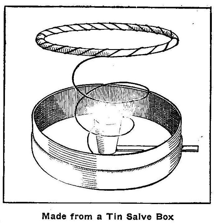
Made from a Tin Salve Box
Indoor photographs are made much better with the use of a
flashlight than by depending on light from windows. The lighting
can be made from any direction to suit the operator. If lighting
flash powder when not in a regular flash lamp the flash cannot be
depended upon and in some instances is dangerous. To make a
simple and inexpensive flash lamp, first secure from your
druggist an empty salve box about 3 in. in diameter. While at the
drug store get 3 ft. of small rubber tubing; this will cost about
15 cents. Now visit the tin shop and get a small piece of scrap
tin 3 or 4 in. square; a piece of brass or steel wire, about the
size of stove pipe wire, 14 in. long. These with a strip of light
asbestos paper and
some small iron wire, about the size of door
screen wire, will complete the material list.
Carefully punch a hole through the salve box on one side near the
bottom with a 10-penny nail. Cut a strip of tin 2 in. long and
about 3/8 in. wide and roll this around an 8-penny nail so as to
form a small tube which will just fit the hole made in the salve
box. Next roll up a strip of tin 1/2 in. wide into a small cup
about 3/8 in. in diameter at one end and 1/4 in. at the other.
Place the tube in the nail hole so that one end comes almost to
the center of the box inside and the other end projects about 1/2
in. outside the box. Cut out a little place for the tube to enter
the cup at the small end and then solder the tube and cup to the
bottom of the box as shown in the illustration. The tube and cup
should be well soldered on the seams to make them airtight. Bend
a ring on one end of the larger piece of wire, making it 2-1/2
in. in diameter and form the remaining portion of the wire into a
spiral, soldering the end in the bottom of the box near the cup.
Wrap the ring at the top of the spiral piece of wire all the way
around with the strip of asbestos paper,
wrapping them together
over and over until the entire ring is covered. Slip the end of
the rubber tube over the tin tube on the side of the box and the
flash lamp is complete.
To make a flash with this lamp fill the little cup in the center
with flash powder and moisten the
asbestos ring with alcohol.
When all is ready for the picture the alcohol is lighted and a
quick blow of the breath through the rubber tube will force the
flash powder upward into the flame and cause the flash.
When through with the lamp place the cover over it, pushing the
asbestos ring down inside the box.
Wind the rubber tubing around the box and you have a neat outfit
that can be carried in the pocket.
Photographing the New Moon
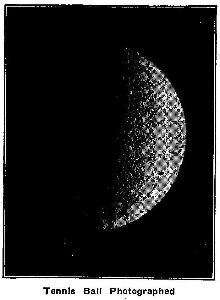
Tennis Ball Photographed
To make a photograph of the moon is quite difficult and no good
picture can be made without an expensive apparatus. At home and
with your own hand camera you can make a good picture of the new
moon by the use of a flash light on a tennis ball, the tennis
ball taking the part of the moon. The ball is suspended in front
of a black cloth screen, the camera focused by holding a burning
match near the ball and the exposure made by burning a small
quantity of flash powder at one side and a little below the ball.
The light from the flash only striking one side of the ball gives
the effect of the new moon.
Photo by M. M. Hunting, Dayton, O.
Old-Time Magic—Part II
Removing Scissors from a Cord
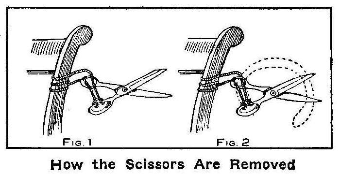
How the Scissors Are Removed
A piece of strong cord is doubled and fastened to a pair of
scissors with a slip knot, as shown in Fig. 1. After passing the
ends of the cord through the thumb hole of the scissors they are
tied fast to a chair, door knob or any other object that may be
of sufficient size to make the ends secure. The trick is to
release the scissors without cutting the cord.
Take hold of the loop end of the cord in the lower handle and
drawing it first through the upper handle and then completely
over the blades of the scissors, as shown in Fig. 2. This is very
simple when you know how, but puzzling when the trick is first
seen.
Coin and Card on the First Finger
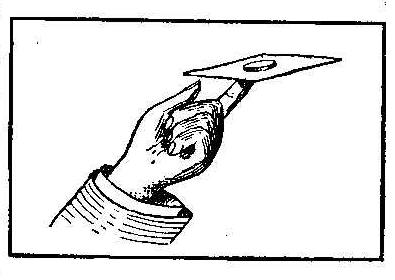
This is a simple trick that many can do at the first attempt,
while others will fail time after time. It is a good trick to
spring upon a company casually if you have practiced it
beforehand. A playing card is balanced on the tip of the
forefinger and a penny placed on top immediately over the finger
end, as shown in the sketch. With the right hand forefinger and
thumb strike the edge of the card sharply. If done properly the
card will flyaway, leaving the penny poised on the finger end.
How to Make Sealing Wax Hat Pins
Select a stick of sealing wax of the desired color for the
foundation of the hat pin. Hold the end of the stick over a flame
until the wax is soft enough to drop; then put it on the hat-pin
head. When sufficient wax has adhered to the pin, hold the lump
over the flame, revolving the pin at the same time so the wax
will not drop and the head will form a round ball. The head can
be made in any shape desired while warm. When the desired shape
has been obtained, cool thoroughly in cold water and dry
carefully.
Stripes and designs may be put on the foundation by applying
drops of other brilliant colored wax, and by careful manipulation
the wax when warm can be made to flow around the pin head and
form pretty stripes and designs. If a certain color is to be more
prominent, the wax to make this color must be applied last and
the pin put through the flame again. Cool in water and dry, as
before, and pass once more through the flame to obtain the
luster.
Old-Time Magic-Part III
Disappearing Coin
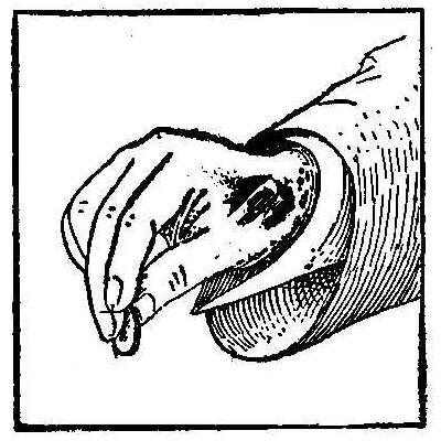
While this is purely a sleight-of-hand trick, it will take very
little practice to cause the coin to disappear instantly. Take a
quarter of a dollar between the thumb and finger, as shown, and
by a rapid twist of the fingers whirl the coin and at the same
time close the hand, and the coin will disappear up your coat
sleeve. On opening the hand the coin will not be seen. Take three
quarters and hold one in the palm of the left hand, place the
other two, one between the thumb and finger of each hand, then
give the coin in the right hand a whirl, as described, closing
both hands quickly. The coin in the right hand will disappear up
your sleeve, and the left hand on being unclosed will contain two
quarters, while the one in the right shall have disappeared.
Sticking a Coin Against the Wall
Cut a small notch in a coin—ten cent piece or quarter will do—so
a small point will project. When this is pressed firmly against a
wood casing or partition the coin will stick tightly.
A Chinese Outdoor Game
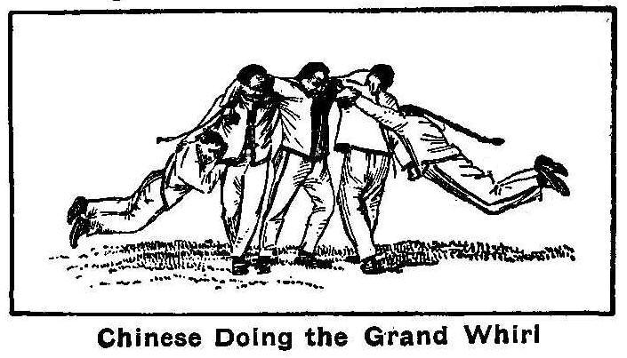
Chinese Doing the Grand Whirl
The accompanying illustration shows the “grand whirl,” or the
Chinese students’ favorite game. This game is played by five
persons, four of them turning around the fifth or central figure
with their arms locked about each other and the two outside
persons swinging in midair with their bodies almost horizontal.
Home-Made Photograph of a Lightning Flash
How many times has each amateur photographer tried to photograph
the lightning’s flash? Some good pictures have been obtained by a
ceaseless effort on the part of the operator. Here is a method by
which you can make a picture of a streak of lightning on a clear
night in your own house. Paste two strips of black paper on a
piece of glass that is 10 in. square so as to leave a clear space
through the center 2-in. or more in width. Smoke this uncovered
space over a candle’s flame until the soot is thick enough to
prevent light passing through. Take a sharp lead pencil and
outline a flash of lightning upon the smoked surface, using a
fine needle to make the smaller lines, and then set the glass up
against the back of two boxes which are set to have a space
between them of 4 or 5 in.
A lighted candle is held behind the glass so the light will shine
through for focusing the camera. After darkening the room set
your camera ready for the exposure and burn a small quantity of
flash light powder in the same place in which the candle was
held. This will make an impression upon the plate of the flash
drawn on the smoked glass.
How to Make a Static Machine
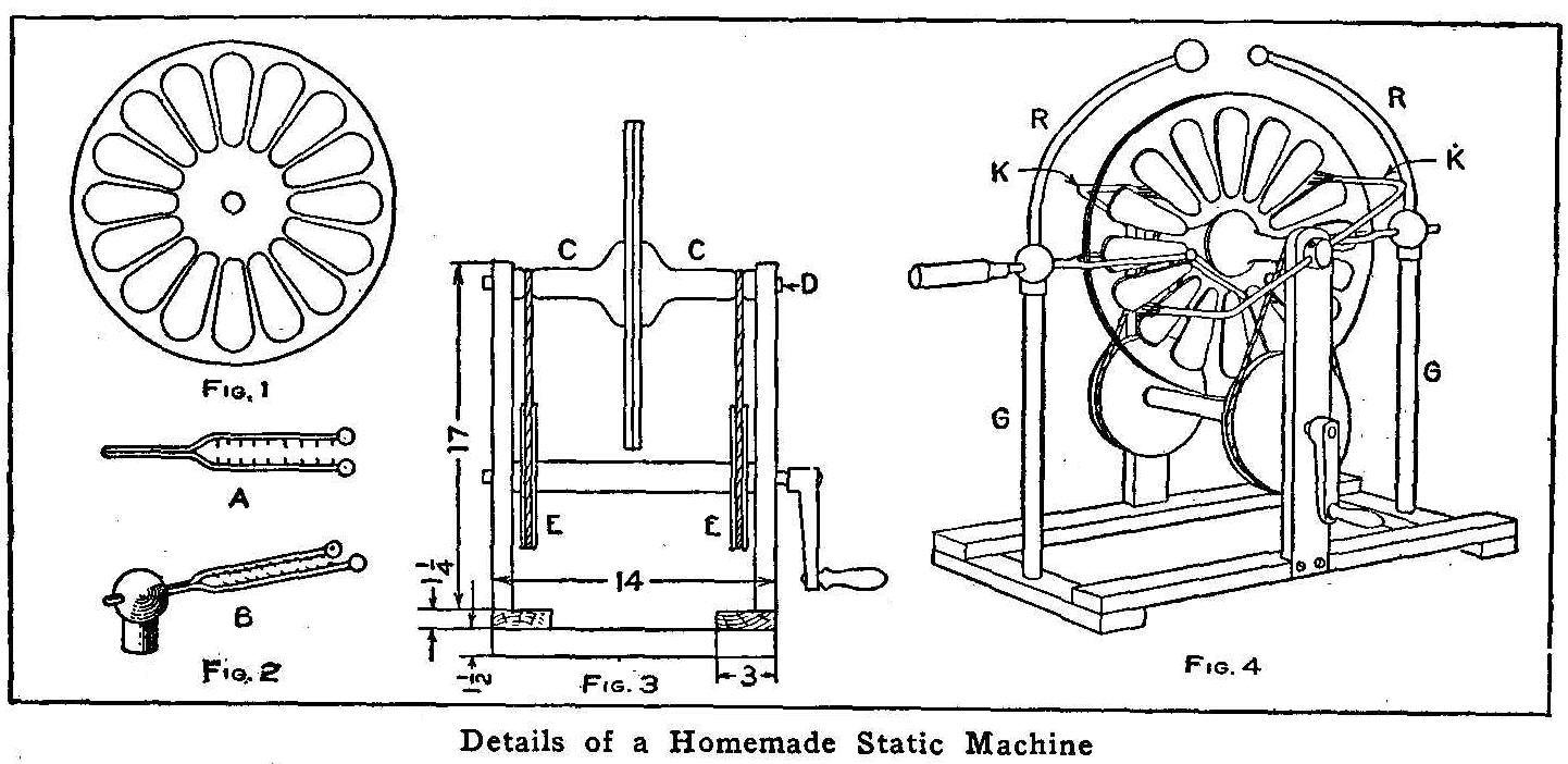
Details of a Homemade Static Machine
Static electricity is produced by revolving glass plates upon
which a number of sectors are cemented; these sectors, passing
through neutralizing brushes, distribute electric charges to
collecting combs attached to discharging rods. The glass selected
for the plates must be clear white glass, free from wrinkles, and
of a uniform thickness. Two plates are necessary to make this
machine, and the glass should be of sufficient size to cut a
circular plate 16-in. in diameter. A hole must be made exactly in
the center of each plate, and this should be done before cutting
the circle. One of the best ways to make the hole is to drill the
glass with a very hard-tempered drill, the cutting edge of which
should be kept moistened with 2 parts turpentine and 1 part sweet
oil while drilling. The hole is to be made 3/4 in. in diameter.
The circle is then marked on each plate and cut with a glass
cutter. The plates are trued up, after they are mounted, by
holding a piece of emery wheel to the edges while they are
turning. Water should be applied to the edges while doing the
work.
The sectors are cut from tinfoil, 1-1/2 in. wide at one end, 3/4
in. at the other, and 4 in. long. A thin coat of shellac varnish
is applied to both sides of the plates, and 16 sectors put on one
side of each plate, as shown in Fig. 1. The divisions can be
marked on the opposite side of the plate and a circle drawn as a
guide to place the sectors at proper intervals.
The sectors should lie flat on the glass with all parts smoothed
out so that they will not be torn from their places as the plates
revolve. The shellac should be tacky when the pieces of tinfoil
are put in place.
The collectors are made, as shown in Fig. 2, from about 1/4-in.
copper wire with two brass balls soldered to the ends. The fork
part is 6 in. long and the shank 4 in. Holes are drilled on the
inside of the forks, and pins inserted and soldered. These pins,
or teeth, should be long enough to be very close to the sectors
and yet not scratch them when the plates are turning.
The frame of the machine is made from any kind of finished wood
with dimensions shown in Fig. 3, the side pieces being 24 in.
long and the standards 3 in. wide. The two pieces, C C, Fig. 3,
are made from solid, close grained wood turned in the shape
shown, with the face that rests against the plate 4 in. in
diameter, and the outer end 1-1/2 in. in diameter, the smaller
end being turned with a groove for a round belt. Before turning
the pieces a hole is bored through each piece for the center, and
this hole must be of such a size as to take a brass tube that has
an internal diameter of 3/4 in. The turned pieces are glued to
the glass plates over the center holes and on the same side on
which the sectors are fastened. Several hours’ time will be
required for the glue to set. A fiber washer is then put between
the plates and a brass tube axle placed through the hole. The
plates, turned wood pieces, and brass axle turn on a stationary
axle, D.
The drive wheels, EE, are made from 7/8-in. material 7 in. in
diameter, and are fastened on a round axle cut from a broom
handle. This wood axle is centrally bored to admit a metal rod
tightly, and extends through the standards with a crank attached
to one end. Two solid glass rods, GG, Fig. 4, 1 in. in diameter
and 15 in. long, are fitted in holes bored into the end pieces of
the frame. Two pieces of 1-in. brass tubing and the discharging
rods, RR, are soldered into two hollow brass balls 2 or 2-1/2 in.
in diameter. The shanks of the collectors are fitted in these
brass balls with the ends extending, to which insulating handles
are attached. Brass balls are soldered to the upper ends of the
discharging rods, one having a 2-in. ball and the other one 3/4
in. in diameter. Caps made from brass are fitted tightly on the
ends of the stationary shaft, D, and drilled through their
diameter to admit heavy copper rods, KK, which are bent as shown.
Tinsel or fine wire such as contained in flexible electric wire
are soldered to the ends of these rods, and the brushes thus made
must be adjusted so they will just touch the plates. The caps are
fitted with screws for adjusting the brushes. These rods and
brushes are called the neutralizers. A little experimenting will
enable one to properly locate the position of the neutralizers
for best results.
Contributed by C. Lloyd Enos, Colorado City, Colo.
A Concrete Swimming Pool
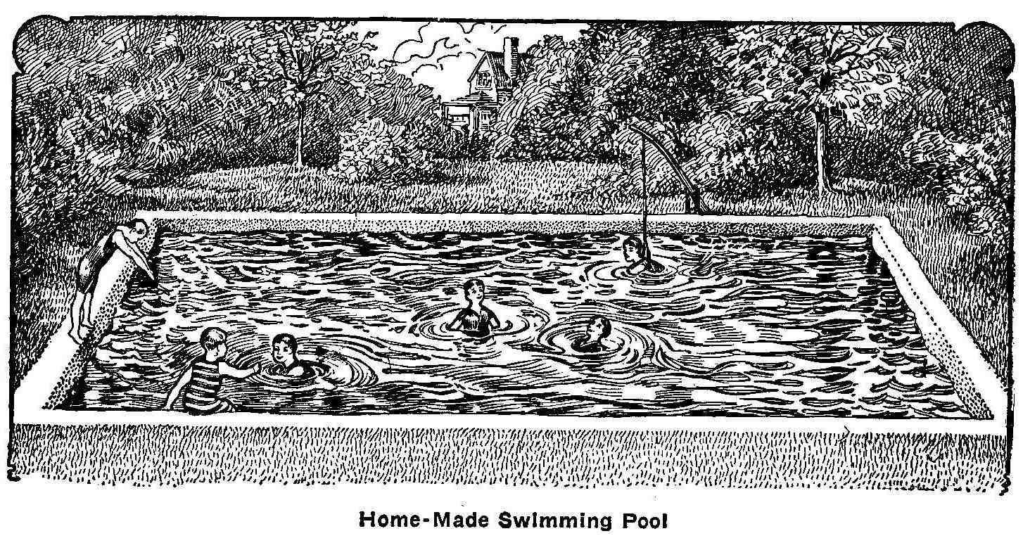
Home-Made Swimming Pool
Several boys from a neighborhood in the suburbs of a large city
concluded to make for themselves a swimming tank of concrete. The
money was raised by various means to purchase the cement, and the
work was done by themselves. The ground was selected in a
secluded spot in a neighbor’s back yard and a hole dug to a depth
of 4 ft., 12 ft. wide and 22 ft. long. The concrete was made by
mixing 1 part cement, 4 parts sand and 10 parts gravel together
and the bulk moistened with water. The bottom was made the same
as laying a sidewalk, and forms were only used for the inside of
the surrounding wall. The tank may be hidden with shrubbery or
vines planted to grow over a poultry wire fence.
Old-Time Magic-Part IV
Cutting a Thread Inside of a Glass Bottle
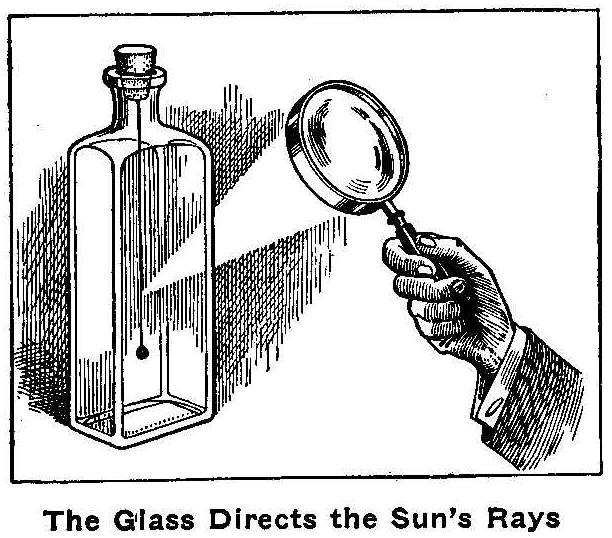
The Glass Directs the Sun’s Rays
This is a trick which can only be performed when the sun shines,
but it is a good one. Procure a clear glass bottle and stick a
pin in the lower end of the cork. Attach a thread to the pin and
tie a small weight to the end of the thread so it will hang
inside the bottle when the cork is in place. Inform your audience
that you will sever the thread and cause the weight to drop
without removing the cork.
All that is required to perform the feat is to hold a magnifying
glass so as to direct the sun’s rays on the thread. The thread
will quickly burn and the weight fall.
Removing a Key from a Double String
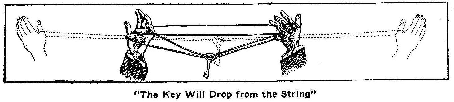
“The Key Will Drop from the String”
Tie the ends of a 5-ft. string together, making a double line on
which a key is placed and the string held as shown by the dotted
lines in the sketch. Turn the palms of the hands toward you and
reach over with the little finger of the right hand and take hold
of the inside line near the left-hand thumb. Reverse the
operation and take hold of the inside line near right-hand thumb
with the little finger of the left hand. You will then have the
string as it appears in the sketch. Quickly let loose of the
string with a little finger on one hand and a thumb on the other
and pull the string taut. The key will drop from the string.
How to Bore a Square Hole
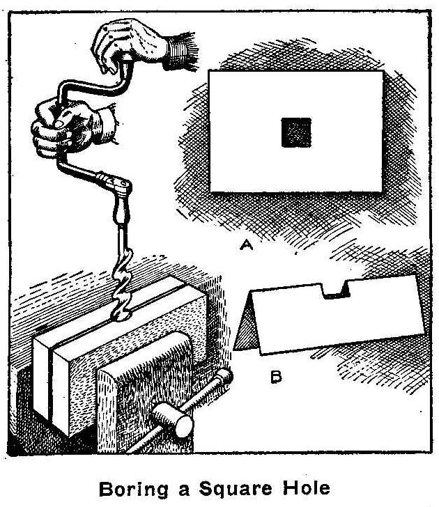
Boring a Square Hole
You would not consider it possible to bore a square hole in a
piece of cardboard, yet such a thing can be done. Take a
cardboard or a thin piece of wood, fold and place it between two
pieces of board with the fold up; the boards are then put in a
vise as shown. Start the bit with the screw point in the fold,
using a 1-in. bit, and bore a hole 1/2 in. deep. When the
cardboard is taken from the vise it will appear as shown at B and
when unfolded, as at A.
How To Make Copper Trays
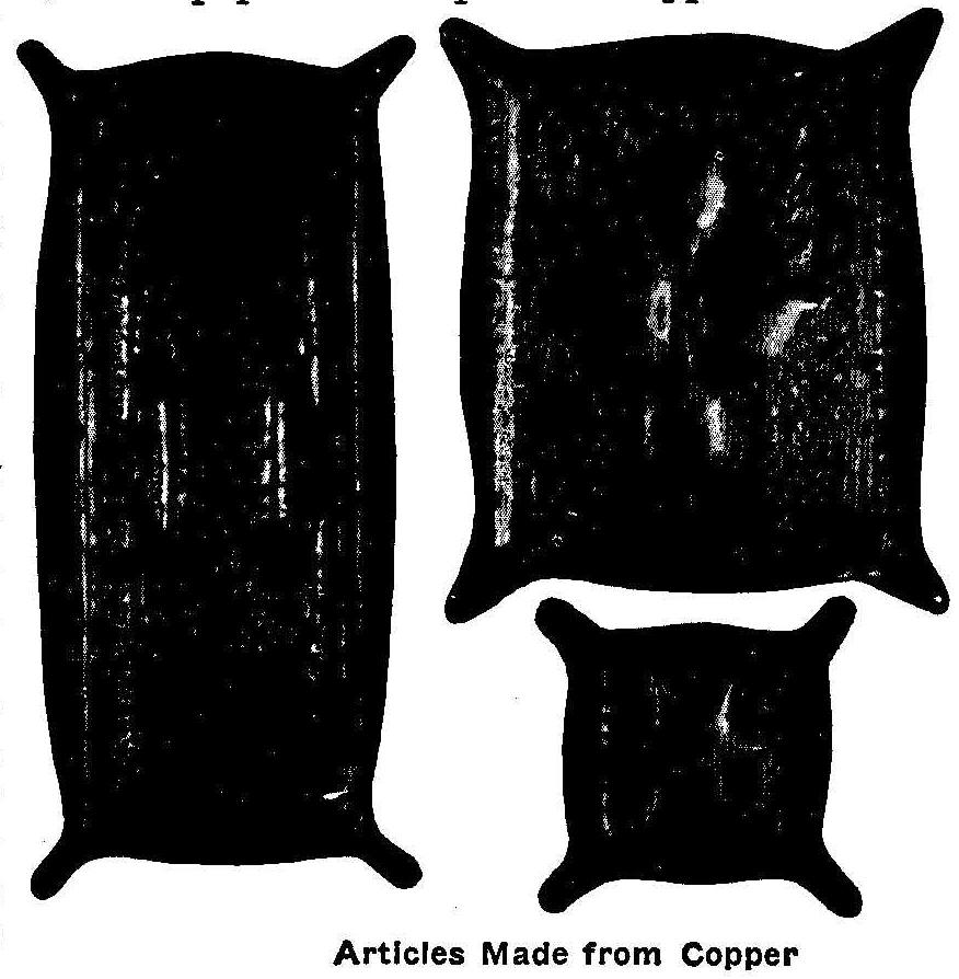
Articles Made from Copper
Copper trays such as are shown in the accompanying illustration
are very useful as well as ornamental about the house. They can
be used to keep pins and needles, pens and pencils, or cigar
ashes, etc. They are easily made, require no equipment in the way
of tools except what are usually found about the house, unless it
would be the metal shears, and when the decorations are well
designed and the metal nicely colored, they make attractive
little pieces to have about.
The first thing to do in preparation for making them is to
prepare the design. Simple designs work out better than fussy
ones and are more likely to be within the ability of the amateur.
Having determined the size of the tray, draw on paper an oblong
to represent it. Inside this oblong, draw another one to
represent the lines along which the metal is to be bent up to
form the sides. Inside this there should be drawn still another
oblong to represent the margin up to which the background is to
be worked. The trays shown are 5-3/4 by 6-3/4 in., the small ash
tray 4 by 4 in., the long pen and pencil tray 4-3/4 by 9-1/2 in.
The second oblong was 3/4 in. inside the first on all, and the
third one 1/4 in. inside the second on all.
If the decoration is to have two parts alike—symmetrical—divide
the space with a line down the middle. Draw one-half the design
free hand, then fold along this line and trace the second half
from this one. If the lines have been drawn with soft pencil,
rubbing the back of the paper with a knife handle will force
enough of the lead to the second side so that the outline can be
determined. Four-part symmetry will require two lines and two
foldings, etc.
For the metal working there will be needed a pair of tin shears,
two spikes, file, flat and round-nosed pliers, screw-driver and
sheet copper of No. 23 gauge. Proceed as follows: 1. Cut off a
piece of copper so that it shall have 1/2 in. extra metal on each
of the four sides. 2. With a piece of carbon paper trace upon the
copper lines that shall represent the margin of the tray proper
and the lines along which the upturned sides of the tray are to
be bent; also trace the decorative design. 3. With a nail make a
series of holes in the extra margin, about 3/4-in. apart and
large enough to take in a 3/4-in. slim screw. 4. Fasten the
metal to a thick board by inserting screws in these holes. 5.
With a 20-penny wire nail that has the sharpness of its point
filed off, stamp the background promiscuously. By holding the
nail about 1/4 in. above the work and striking it with the
hammer, at the same time striving to keep it at 1/4 in. above the
metal, very rapid progress can be made. This stamping lowers the
background and at the same time raises the design. 6. Chase or
stamp along the border of the design and background, using a nail
filed to chisel edge. This is to make a clean, sharp division
between background and design. 7. When the stamping is completed,
remove the screws and the metal from the board and cut off the
extra margin with the metal shears. File the edges until they are
smooth to the touch. 8. With the flat pliers “raise” one side of
the tray, then the other side. 9. Raise the ends, adjusting the
corners as shown in the illustration. Use the round-nosed pliers
for this purpose.
Copper is frequently treated chemically to give it color. Very
pretty effects may be obtained by covering the tray with
turpentine, then moving it about over a flame such as a bunsen
burner until the turpentine burns off. The copper will “take on”
almost all the colors of a rainbow, and the effect will be most
pleasing.
Photograph of a Clown Face
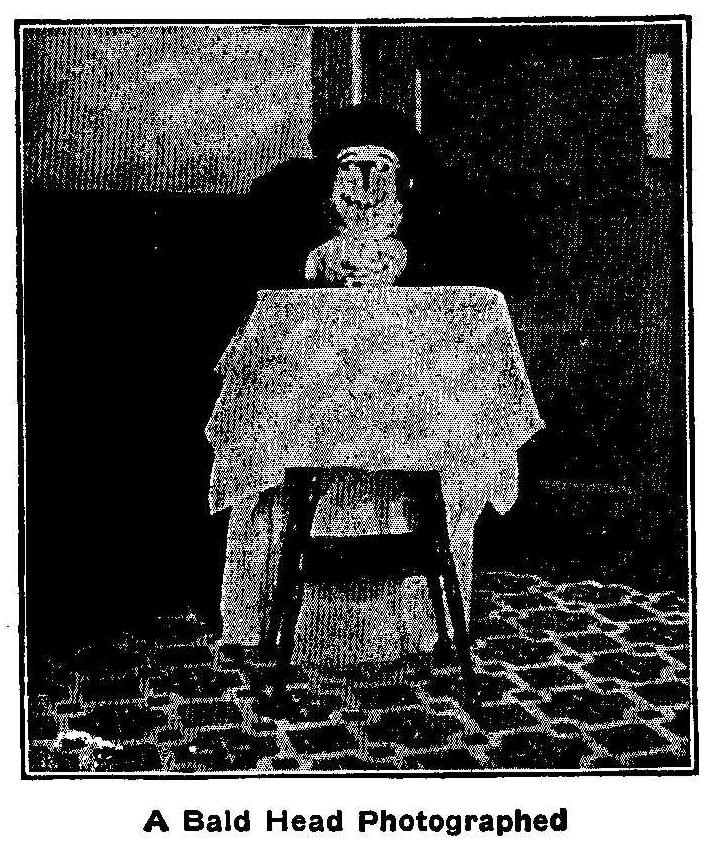
A Bald Head Photographed
At first glance the accompanying photograph will appear as if the
person photographed is wearing a false face or has his face
painted like a clown. On close observation you will notice that
the face is made on the bald head of the person sitting behind
the table. The eyes, nose and mouth are cut from black paper and
pasted on the bald spot. The subject’s face is horizontal and
resting upon his hands.
Finger Mathematics
By Charles C. Bradley
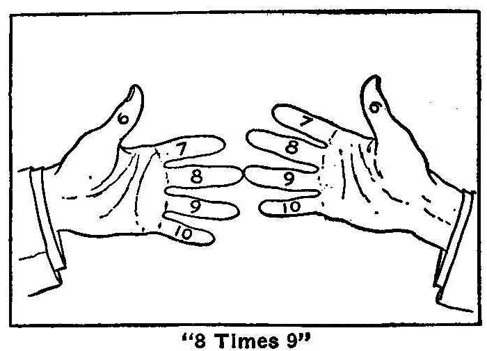
“8 Times 9”
All machinists use mathematics. Ask a machinist what would be the
product of 9 times 8 and his ready reply would be 72, but change
the figures a little and say 49 times 48 and the chances are that
instead of replying at once he will have to figure it out with a
pencil. By using the following method it is just as easy to tell
at a glance what 99 times 99 are as 9 times 9. You will be able
to multiply far beyond your most sanguine expectations.
In the first numbering, begin by holding your hands with the
palms toward the body and make imaginary numbers on the thumbs
and fingers as follows: Thumbs, 6; first fingers, 7; second
fingers, 8; third fingers, 9, and fourth fingers, 10. Suppose you
desire to multiply 8 by 9, put the eighth finger on one hand
against the ninth finger of the other hand as shown.
The two joined fingers and all the fingers above them (calling
the thumbs fingers) are called the upper fingers and each has a
value of ten, which tens are added. All the fingers below the
joined fingers are termed the lower fingers, and each of the
lower fingers represents a unit value of one. The sum of the
units on one hand should be multiplied by the sum of the units on
the other hand. The total tens added to this last named sum will
give the product desired. Thus: Referring to above picture or to
your hands we find three tens on the left hand and four tens on
the right, which would be 70. We also find two units on the left
hand and one on the right. Two times one are two, and 70 plus 2
equals 72, or the product of 8 times 9.
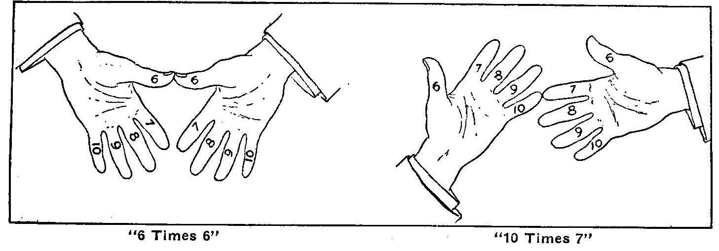
“6 Times 6” “10 Times 7”
Supposing 6 times 6 were the figures. Put your thumbs together;
there are no fingers above, so the two thumbs represent two tens
or 20; below the thumbs are four units on each hand, which would
be 16, and 20 plus 16 equals 36, or the product of 6 times 6.
Supposing 10 times 7 is desired. Put the little finger of the
left hand against the first finger of the right hand. At a glance
you see seven tens or 70. On the right hand you have three units
and on the left nothing. Three times nothing gives you nothing
and 70 plus nothing is 70.
In the second numbering, or numbers above 10, renumber your
fingers; thumbs, 11; first fingers, 12, etc. Let us multiply 12
by 12.
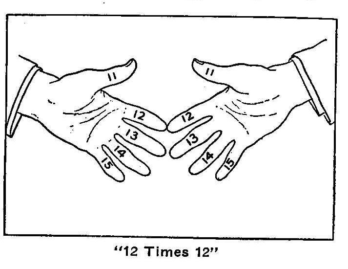
“12 Times 12”
Put together the tips of the fingers labeled 12. At a glance you
see four tens or 40. At this point we leave the method explained
in Case 1 and ignore the units (lower fingers) altogether. We go
back to the upper fingers again and multiply the number of upper
fingers used on the one hand by the number of upper fingers used
on the other hand, viz., 2 times 2 equals 4. Adding 4 to 40 gives
us 44. We now add 100 (because anything over 10 times 10 would
make over 100) and we have 144, the product of 12 times 12.
The addition of 100 is arbitrary, but being simple it saves time
and trouble. Still, if we wish, we might regard the four upper
fingers in the above example as four twenties, or 80, and the six
lower fingers as six tens, or 60; then returning to the upper
fingers and multiplying the two on the right hand by the two on
the left we would have 4; hence 80 plus 60 plus 4 equals 144;
therefore the rule of adding the lump sum is much the quicker and
easier method.
Above 10 times 10 the lump sum to add is 100; above 15 times 15
it is 200; above 20 times 20, 400; 25 times 25, 600, etc., etc.,
as high as you want to go.
In the third numbering to multiply above 15 renumber your
fingers, beginning the thumbs with 16, first finger 17, and so
on. Oppose the proper finger tips as before, the upper fingers
representing a value of 20. Proceed as in the first numbering and
add 200. Take For example 18 times 18.
At a glance we see six twenties plus 2 units on left hand times 2
units on right hand plus 200 equals 324.
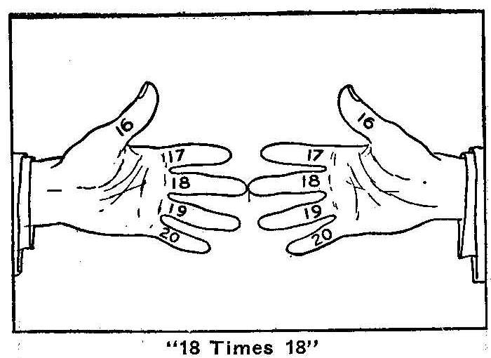
“18 Times 18”
In the fourth numbering the fingers are marked, thumbs, 21, first
fingers 22, etc., the value of the upper fingers being 20.
Proceed as in the second lumbering, adding 400 instead of 100.
Above 25 times 25 the upper fingers represent a value of 30 each
and after proceeding as in the third numbering you add 600
instead of 200.
This system can be carried as high as you want to go, but you
must remember that for figures ending in 1, 2, 3, 4 and 5 proceed
as in the second numbering. For figures ending in 6, 7, 8, 9 and
10 the third numbering applies.
Determine the value of the upper fingers whether they represent
tens, twenties, thirties, forties, or what. For example, any two
figures between 45 and 55, the value of the upper fingers would
be 50, which is the half-way point between the two fives. In 82
times 84 the value of the upper fingers would be 80 (the half-way
point between the two fives, 75 and 85, being 80). And the lump
sum to add.
Just three things to remember: Which numbering is to follow,
whether the one described in second or third numbering; the value
which the upper fingers have; and, lastly, the lump sum to add,
and you will be able to multiply faster and more accurately than
you ever dreamed of before.
Optical Illusions
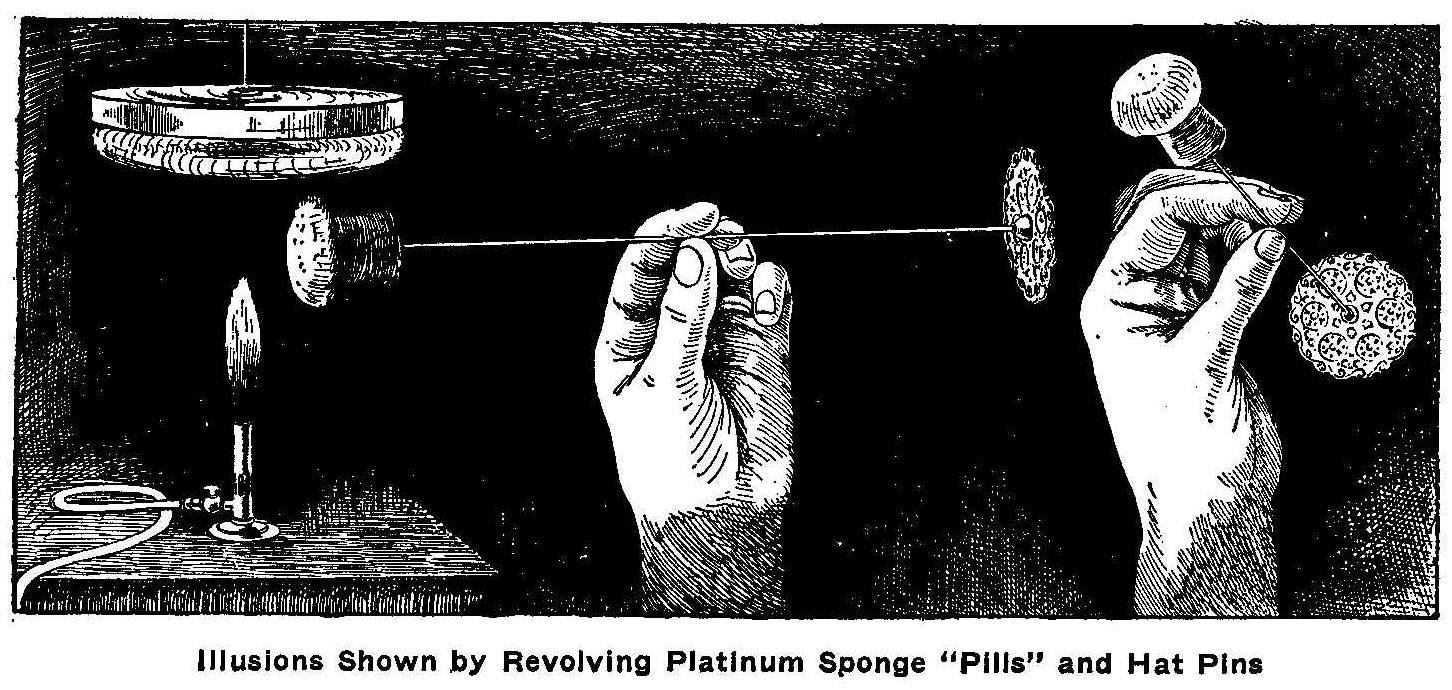
Illusions Shown by Revolving Platinum Sponge “Pills” and Hat Pins
If a person observes fixedly for some time two balls hanging on
the end of cords which are in rapid revolution, not rotation,
about a vertical axis, the direction of revolution will seem to
reverse. In some experiments two incandescent “pills” of platinum
sponge, such as an used for lighting gas-burners, were hung in
tiny aluminum bells from a mica vane wheel which was turned
constantly and rapidly in one direction by hot air from a gas
flame to keep the platinum in a glow. The inversion and reversion
did not take place, as one might suppose, at the will of the
observer, but was compulsory and followed regular rules. If the
observer watches the rotating objects from the side, or from
above or from below, the inversion takes place against his will;
the condition being that the image on the retina shall be
eccentric. It takes place also, however, with a change in the
convergence of the optical axes, whether they are parallel to
each other or more convergent. Also when the image on the retina
is made less distinct by the use of a convex or concave lens, the
revolution seems to reverse; further, in the case of a
nearsighted person, when he removes his spectacles, inversion
results every time that the image on the retina is not sharp. But
even a change in the degree of indistinctness causes inversion.
The cause of this optical illusion is the same where the wings of
windmills are observed in the twilight as a silhouette. It is
then not a question of which is the front or the back of the
wheel, but whether one of the wings or the other comes towards
the observer. The experiment is made more simple by taking a hat
pin with a conspicuous head, holding it firmly in a horizontal
position, and putting a cork on the point. Looking at it in
semi-darkness, one seems to see sometimes the head of the pin,
sometimes the point towards him, when he knows which direction is
right. The inversion will be continued as soon as one observes
fixedly a point at the side. Here it is a question of the
perception of depth or distance; and this is the same in the case
of the rotating balls; the direction of seeming revolution
depends on which one of them one considers to be the front one
and which the rear one.
From the foregoing the following conclusion may be reached: When,
in the case of a perception remitting two appearances, one
fixedly observes one of these and then permits or causes change
in the sharpness of the image on the retina, the other appearance
asserts itself.
Steam Engine Made from Gas Pipe and Fittings
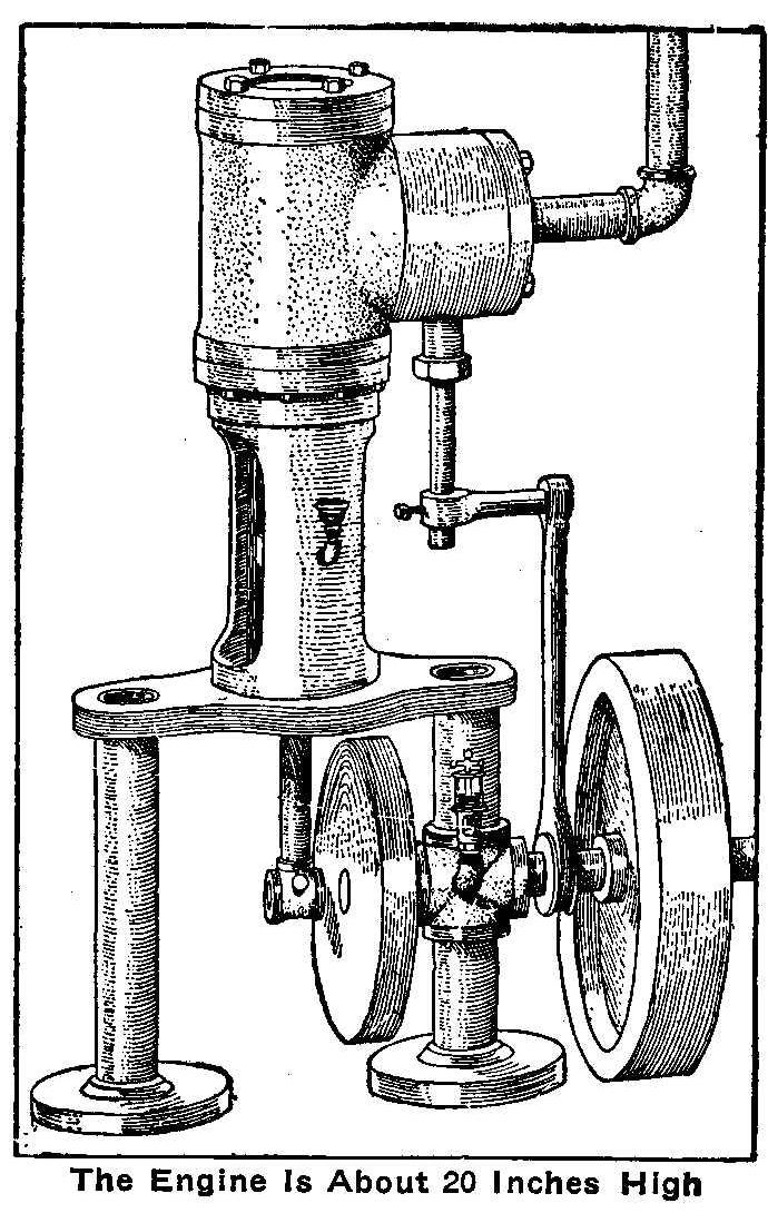
The Engine Is About 20 Inches High
Almost all the material used in the construction of the parts for
the small steam engine illustrated herewith was made from gas
pipe and fittings. The cylinder consists of a 3-in. tee, the
third opening being threaded and filled with a cast-iron plug
turned to such a depth that when the interior was bored out on a
lathe the bottom of the plug bored to the same radius as the
other part of the tee. The outside end of the plug extended about
1/4-in. and the surface was made smooth for the valve seat. A
flat slide valve was used.
The ports were not easy to make, as they had to be drilled and
chipped out. The steam chest is round, as it had to be made to
fit the round tee connection. The crosshead runs in guides made
from a piece of gas pipe with the sides cut out and threads cut
on both ends. One end is screwed into a rim turned on the
cylinder head and the other is fitted into an oblong plate. Both
ends of this plate were drilled and tapped to receive 1-1/2-in.
pipe.
The main frame consists of one 1-1/2 in. pipe 10 in. long and one
made up from two pieces of pipe and a cross to make the whole
length 10 in. These pipes were then screwed into pipe flanges
that served as a base. The open part of the cross was babbitted
to receive the main shaft. The end of the shaft has a pillow
block to take a part of the strain from the main bearing. The
eccentric is constructed of washers. While this engine does not
give much power, it is easily built, inexpensive, and anyone with
a little mechanical ability can make one by closely following out
the construction as shown in the illustration.
Contributed by W. H. Kutscher, Springfield, Ill.
How to Make a Copper Bowl
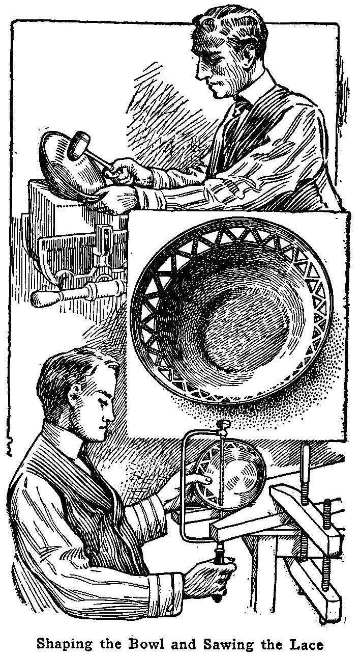
Shaping the Bowl and Sawing the Lace
To make a copper bowl, such as is shown in the illustration,
secure a piece of No. 21 gauge sheet copper of a size sufficient
to make a circular disk 6-1/2 in. in diameter.
Cut the copper to the circular form and size just mentioned, and
file the edge so that it will be smooth and free from sharp
places. With a pencil compass put on a series of concentric rings
about 1/2 in. apart. These are to aid the eye in beating the bowl
to form.
The tools are simple and can be made easily. First make a
round-nosed mallet of some hard wood, which should have a
diameter of about 1-1/4 in, across the head. If nothing better is
at hand, saw off a section of a broom handle, round one end and
insert a handle into a hole bored in its middle. Next take a
block of wood, about 3 by 3 by 6 in., and make in one end a
hollow, about 2 in. across and 1/2 in. deep. Fasten the block
solidly, as in a vise, and while holding the copper on the
hollowed end of the block, beat with the mallet along the
concentric rings.
Begin at the center and work along the rings—giving the copper a
circular movement as the beating proceeds—out toward the rim.
Continue the circular movement and work from the rim back toward
the center. This operation is to be continued until the bowl has
the shape desired, when the bottom is flattened by placing the
bowl, bottom side up, on a flat surface and beating the raised
part flat.
Beating copper tends to harden it and, if continued too long
without proper treatment, will cause the metal to break. To
overcome this hardness, heat the copper over a bed of coals or a
Bunsen burner to a good heat. This process is called annealing,
as it softens the metal.
The appearance of a bowl is greatly enhanced by the addition of a
border. In the illustration the border design shown was laid out
in pencil, a small hole was drilled with a band drill in each
space and a small-bladed metal saw inserted and the part sawed
out.
To produce color effects on copper, cover the copper with
turpentine and hold over a Bunsen burner until all parts are well
heated.
Cleaning Furniture
After cleaning furniture, the greasy appearance may be removed by
adding some good, sharp vinegar to the furniture polish. Vinegar,
which is nothing else than diluted acetic acid, is one of the
best cleansers of dirty furniture.
Melting Lead in Tissue Paper
Take a buckshot, wrap it tightly in one thickness of tissue
paper, and, holding the ends of the paper in the fingers of each
hand, place the part that holds the shot over the flame of a
match just far enough away from the flame not to burn the paper.
In a few seconds unfold the paper and you will find that the shot
has melted without even scorching the paper.
Contributed by W. O. Hay, Camden, S. C.
The Principles of the Stereograph
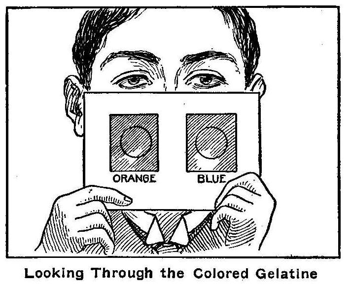
Looking Through the Colored Gelatine
Each of our eyes sees a different picture of any object; the one
sees a trifle more to the right-hand side, the other to the left,
especially when the object is near to the observer. The
stereoscope is the instrument which effects this result by
bringing the two pictures together in the senses. The stereograph
produces this result in another way than by prisms as in the
stereoscope. In the first place there is only one picture, not
two mounted side by side. The stereograph consists of a piece of
card, having therein two circular openings about 1-1/4 in.
diameter, at a distance apart corresponding to the distance
between the centers of the pupils. The openings are covered with
transparent gelatine, the one for the left eye being blue, that
for the right, orange. The picture is viewed at a distance of
about 7 in. from the stereograph. As a result of looking at it
through the stereograph, one sees a colorless black and white
picture which stands out from the background. Try looking at the
front cover of Popular Mechanics through these colored gelatine
openings and the effect will be produced.
If one looks at the picture first with the right eye alone
through the orange glass, and then with the left eye through the
blue glass, one will understand the principle on which the little
instrument works. Looking through the blue glass with the left
eye, one sees only those portions which are red on the picture.
But they seem black. The reason is that the red rays are absorbed
by the blue filter. Through the orange gelatine all the white
portions of the picture seem orange, because of the rays coming
from them, and which contain all the colors of the spectrum; only
the orange rays may pass through. The red portions of the picture
are not seen, because, although they pass through the screen,
they are not seen against the red ground of the picture. It is
just as though they were not there. The left eye therefore sees a
black picture on a red background.
In the same way the right eye sees through the orange screen only
a black picture on a red background; this black image consisting
only of the blue portions of the picture.
Any other part of complementary colors than blue and orange, as
for instance red and green, would serve the same purpose.
The principle on which the stereograph works may be demonstrated
by a very simple experiment. On white paper one makes a picture
or mark with a red pencil. Looking at this through a green glass
it appears black on a green ground; looking at it through a red
glass of exactly the same color as the picture, it, however,
disappears fully.
Through the glass one will see only a regular surface of the
color of the glass itself, and without any picture. Through a red
glass a green picture will appear black.
So with the stereograph; each eye sees a black picture
representing one of the pictures given by the stereoscope; the
only difference being that in the case of the stereograph the
background for each eye is colored; while both eyes together see
a white background.
In the pictures the red and the green lines and dots must not
coincide; neither can they be very far apart in order to produce
the desired result. In order that the picture shall be “plastic,”
which increases the sense of depth and shows the effect of
distance in the picture, they must be a very trifle apart. The
arrangement of the two pictures can be so that one sees the
pictures either in front of or on the back of the card on which
they are printed. In order to make them appear before the card,
the left eye sees through a blue screen, but the red picture
which is seen by it is a black one, and lies to the right on the
picture; and the right eye sees the left-hand picture. The further
apart the pictures are, the further from the card will the
composite image appear.
In the manufacture of a stereoscope the difficulty is in the
proper arrangement of the prisms; with the stereograph, in the
proper choice of colors.
Mercury Make-and-Break Connections for Induction Coils
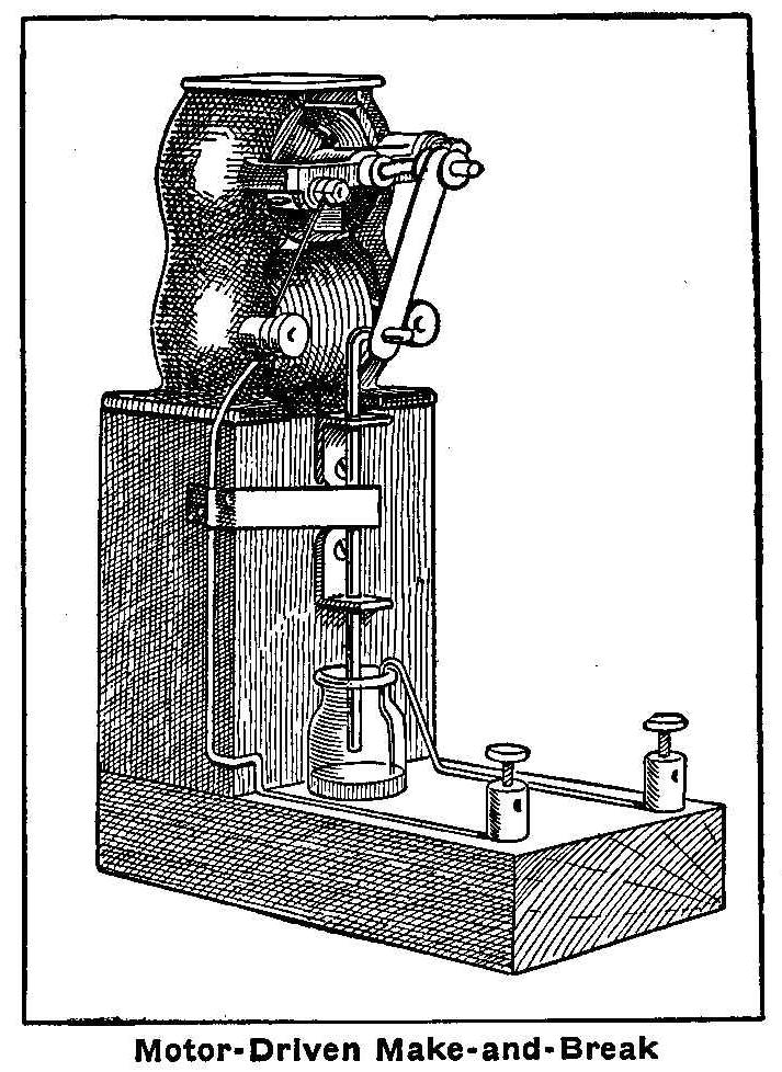
Motor-Driven Make-and-Break
Induction coils operating on low voltage have a make-and-break
connection called the “buzzer” to increase the secondary
discharge. Two types of make-and-break connection are used, the
common “buzzer” operated by the magnetism of the core in the coil
and the mercury
break operated by a small motor. The sketch
herewith shows how to make the motor-operated break. Two blocks
of wood are nailed together in the shape of an L and a small
motor fastened to the top of the vertical piece. The shaft of the
motor is bent about 1/8 in. in the shape of a crank, so that in
turning it will describe a circle 1/4 in. in diameter. A small
connecting bar is cut from a piece of brass 1/8 in. thick, 1/4
in. wide and 1 in. long and a hole drilled in each end; one hole
to fit the motor shaft and the other to slip on a No. 12 gauge
wire. Two L-shaped pieces of brass are fastened to the side of
the block and drilled with holes of such a size that a No. 12
gauge wire will slip through snugly. Place a NO.12 gauge wire in
these holes and bend the top end at right angles.
Put the connecting brass bar on the motor shaft with washers
fitted tight on each side and slip the other end over the bent
end of the wire. Have the wire plenty long so it can be cut to
the proper length when the parts are all in place. A small round
bottle about 1/2 in. in diameter is now fitted in a hole that has
been previously bored into the middle of the bottom block and
close up to the vertical piece. This should only be bored about
half way through the block. The wire is now cut so at the length
of the stroke the end will come to about one-half the depth, or
the middle of the bottle.
Fill the bottle with mercury
to a point so that when the motor is
running, the end of the wire will be in the
mercury for about
one-half of the stroke. Cover the
mercury over with a little
alcohol. A No. 14 gauge iron wire is bent and put into the side
of the bottle with the end extending to the bottom. The other end
of this wire is attached to one binding-post placed at the end of
the bottom block. The other binding-post is connected to a small
brass brush attached to the side of the vertical piece, which is
placed with some pressure on the moving wire. The motor can be
run with a current from a separate course or connected as shown
on the same batteries with the coil. The proper height of the
mercury can be regulated for best
results. The motor must run continuous if the coil is used for
writing code signals, wireless, etc.
Contributed by Haraden Pratt, San Francisco, Cal.
How to Make a Barometer
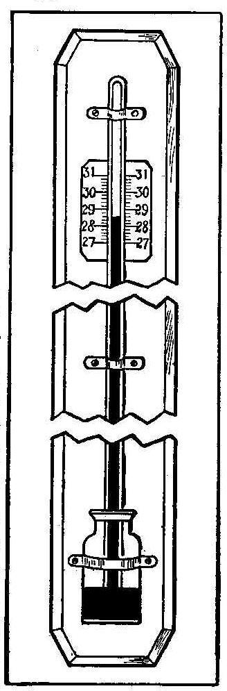
Atmospheric pressure is measured by the barometer. The weight of
the air in round numbers is 15 lb. to the square inch and will
support a column of water 1 in. square, 34 ft. high, or a column
of mercury
(density 13.6) 1 in. square, 30 in. high.
The parts necessary to make a simple barometer are, a glass tube
1/8 in. internal diameter and about 34 in. long, a bottle 1 in.
inside diameter and 2 in. high. Seal one end of the tube by
holding it in the flame of a gas burner, which will soon soften
the glass so it can be pinched together with pliers. Put a little
paraffin in the bottle and melt it by holding the bottle over a
small flame. When cool the paraffin should cover the bottom about
1/16 in. thick. The tube is now to be filled with
mercury. This
may be accomplished with a paper funnel, but before attempting to
put in the mercury,
place a large dish or tray beneath the tube
to catch any mercury
that may accidentally be spilled. Only
redistilled mercury
should be used, and the tube should be
perfectly clean before filling. When the tube is filled to within
1 in. of the open end place the forefinger over the hole and tilt
the tube up and down so all the air will gather at the finger
end. The filling is continued until the tube is full of
mercury.
The glass bottle containing the wax covered bottom is now placed
over the end of the tube and pressed firmly to insure an airtight
fit with the tube. The bottle and tube are inverted and after a
few ounces of mercury
are put in the bottle the tube may be
raised out of the wax, but be careful not to bring its edge above
the surface of the mercury.
The instrument is put aside while the base is being made, or, if
you choose, have the base ready to receive the parts just
described when they are completed. Cut a base from a piece of
7/8-in. pine 3 in. wide and 40 in. long. In this base cut a
groove to fit the tube and the space to be occupied by the bottle
is hollowed out with a chisel to a depth of 3/4 in., so the
bottle rests on one-half of its diameter above the surface of the
board and one-half below. The instrument is made secure to the
base with brass strips tacked on as shown in the sketch. After
the instrument is in place put enough
mercury in the bottle so
the depth of the mercury
above the bottom end of the tube will be about 1/2 in.
The scale is made on a piece or cardboard 2 in. wide and 4 in.
long. The 4 in. are marked off and divided into sixteenths, and
the inches numbered 27 up to 31. The scale is fastened to the
base with glue or tacks and in the position behind the tube as
shown in the sketch. Before fastening the scale, the instrument
should be compared with a standard barometer and the scale
adjusted so both readings are the same. But if a standard
barometer is not available, the instrument, if accurately
constructed, will calibrate itself.
In general, a drop in the mercury
indicates a storm and bad
weather, while a rise indicates fair weather and in winter a
frost. Sudden changes in the barometer are followed by like
changes in weather. The slow rise of the
mercury predicts fair
weather, and a slow fall, the contrary. During the frosty days
the drop of the mercury is followed by a thaw and a rise
indicates snow.
Home-Made Post or Swinging Light
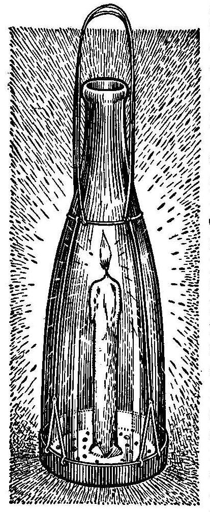
Remove the bottom from a round bottle of sufficient size to admit
a wax or tallow candle. This can be done with a glass cutter or
a hot ring; the size of the outside of the bottle, which is
slipped quickly over the end. Procure a metal can cover, a cover
from a baking powder can will do, a lid fit it on the end where
the bottom was removed. The cover is punched full of holes to
admit the air and a cross cut in the center with the four wings
thus made by the cutting turned up to form a place to insert the
candle. The metal cover is fastened to the bottle with wires as
shown in the sketch. This light can be used on a post or hung
from a metal support.
A Checker Puzzle
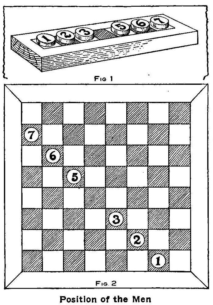
Position of the Men
Cut a block from a board about 3 in. wide and 10 in. long.
Sandpaper all the surfaces and round the edges slightly. Mark out
seven 1-in. squares on the surface to be used for the top and
color the squares alternately white and black. Make six men by
sawing a curtain roller into pieces about 3/8 in. thick. Number
the pieces 1, 2, 3, 5, 6 and 7, and place them as shown in Fig.
1. The puzzle is to make the first three change places with the
last three and move only one at a time. This may be done as
follows:
| Move 1 | Move No. 3 to the center. |
| Move 2 | Jump No. 5 over No. 3. |
| Move 3 | Move No. 6 to No. 5’s place. |
| Move 4 | Jump No. 3 over No. 6. |
| Move 5 | Jump No. 2 over No. 5. |
| Move 6 | Move No. 1 to No. 2’s place. |
| Move 7 | Jump No. 5 over No. 1. |
| Move 8 | Jump No. 6 over No. 2. |
| Move 9 | Jump No. 7 over No. 3. |
| Move 10 | Move No. 3 into No. 7’s place. |
| Move 11 | Jump No. 2 over No. 7. |
| Move 12 | Jump No. 1 over No. 6. |
| Move 13 | Move No. 6 into No. 2’s place. |
| Move 14 | Jump No. 7 over No. 1. |
| Move 15 | Move No. 1 into No, 5’s place. |
After the 15 moves are made the men will have changed places.
This can be done on a checker board, as shown in Fig. 2, using
checkers for men, but be sure you so situate the men that they
will occupy a row containing only 7 spaces.
Contributed by W. L. Woolson, Cape May Point, N.J.
Gold Railroad Signals
Covering railroad signals with gold leaf has taken the place of
painting on some roads. Gold leaf will stand the wear of the
weather for 15 or 20 years, while paint requires recovering three
or four times a year.
How to Make a Bell Tent
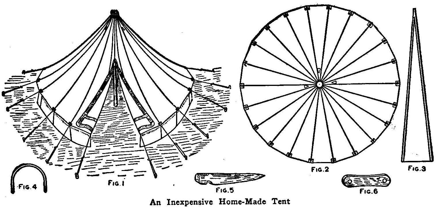
An Inexpensive Home-Made Tent
A bell tent is easily made and is nice for lawns, as well as for
a boy’s camping outfit. The illustrations show a plan of a tent
14-ft. in diameter. To make such a tent, procure unbleached tent
duck, which is the very best material for the purpose, says the
Cleveland Plain Dealer. Make 22 sections, shaped like Fig. 3,
each 10 ft. 6 in. long and 2 ft. 2 in. wide at the bottom,
tapering in a straight line to a point at the top. These
dimensions allow for the laid or lapped seams, which should be
double-stitched on a machine. The last seam sew only for a
distance of 4 ft. from the top, leaving the rest for an opening.
At the end of this seam stitch on an extra gusset piece so that
it will not rip. Fold back the edges of the opening and the
bottom edge of the bell-shaped cover and bind it with wide
webbing, 3 in. across and having eyelets at the seams for
attaching the stay ropes. Near the apex of the cover cut three
triangular holes 8 in. long and 4 in. wide at the bottom and hem
the edges. These are ventilators. Make the tent wall of the same
kind of cloth 2 ft. 2 in. high. Bind it at the upper edge with
webbing and at the bottom with canvas. Also stitch on coarse
canvas 6 in. wide at the bottom, and the space between the ground
and the wall when the tent is raised, fill with canvas edging.
Stitch the upper edge of the wall firmly to the bell cover at the
point indicated by the dotted line, Fig. 2.
For the top of the tent have the blacksmith make a hoop of
1/4-in. round galvanized iron, 6-in. diameter. Stitch the canvas
at the apex around the hoop and along the sides. Make the apex
into a hood and line it with stiff canvas. Have the tent pole 3
in. in diameter, made in two sections, with a socket joint and
rounded at the top to fit into the apex of the tent. In raising
the tent, fasten down the wall by means of loops of stout line
fastened to its lower edge and small pegs driven through them
into the ground, Fig. 5. Run the stay ropes from the eyelets in
the circular cover to stakes (Fig. 5) stuck in the ground. Use
blocks, as in Fig. 6, on the stay ropes for holding the ends and
adjusting the length of the ropes.
Simple X-Ray Experiment
The outlines of the bones of the hand may be seen by holding a
piece of rice paper before the eyes and placing the spare hand
about 12 in. back of the rice paper and before a bright light.
The bony structure will be clearly distinguishable.
Contributed by G.J. Tress, Emsworth, Pa.
How to Make a Candle Shade
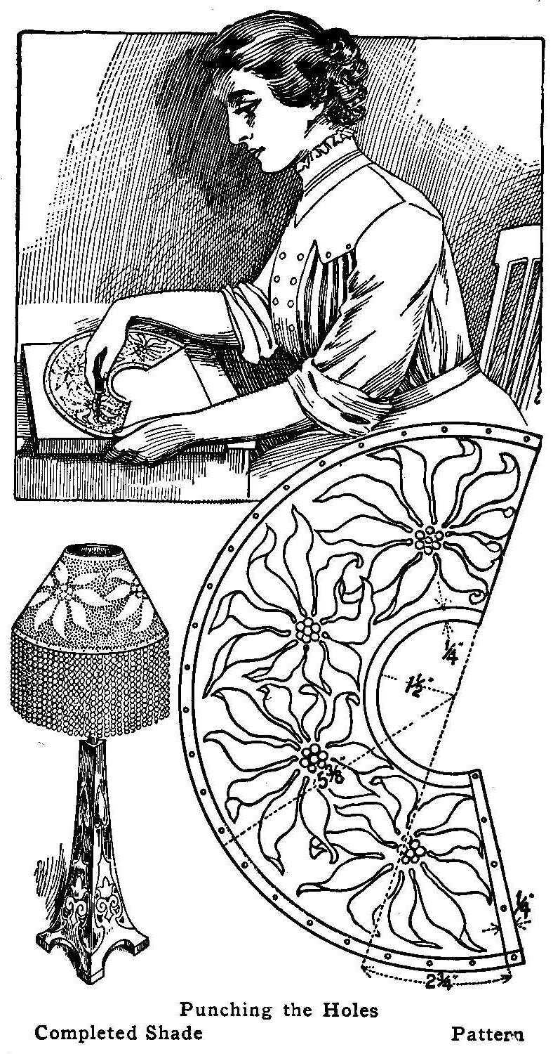
Punching the Holes
Completed Shade Pattern
Lay out the pattern for the shade on a thin piece of paper, 9 by
12 in., making the arcs of the circle with a pencil compass. As
shown in the sketch, the pattern for this particular shade covers
a half circle with 2-3/4 in. added. Allowance must be made for
the lap and as 1/4 in. will do, a line is drawn parallel 1/4 in.
from the one drawn through the center to the outside circle that
terminates the design.
Nail a thin sheet of brass, about 9 in. wide by 12 in. long, to a
smooth board of soft wood, then trace the design on the brass by
laying a piece of carbon paper between the pattern and the brass.
After transferring the design to the brass, use a small awl to
punch the holes in the brass along the outlines of the figures
traced. Punch holes in the brass in the spaces around the
outlined figures, excepting the 1/4-in. around the outside of the
pattern. When all the holes are punched, remove the brass sheet
from the board and cut it along the outer lines as traced from
the pattern, then bend the brass carefully so as not to crease
the figures appearing in relief. When the edges are brought
together by bending, fasten them with brass-headed nails or brads.
If a wood-turning lathe is at hand, the shade can be made better
by turning a cone from soft wood that will fit the sheet-brass
shade after it is shaped and the edges fastened together. The
pattern is traced as before, but before punching the holes, cut
out the brass on the outside lines, bend into shape, fasten the
ends together and place on the wood cone. The holes are now
punched on the outlines traced from the pattern and the open
spaces made full of holes. The holes being punched after the
shade is shaped, the metal will stay and hold the perfect shape
of a cone much better.
The glass-beaded fringe is attached on the inside of the bottom
part with small brass rivets or brads placed about 3/4 in. apart.
The thin sheet brass may be procured from the local hardware
dealer and sometimes can be purchased from general merchandise
stores.
Contributed by Miss Kathryn E. Corr, Chicago.
A Putty Grinder
Having a large number of windows to putty each week, I found it
quite a task to prepare the putty. I facilitated the work by
using an ordinary meat cutter or sausage grinder. The grinder
will soften set putty and will quickly prepare cold putty. It
will not, however, grind old putty or make putty from whiting and
oil.
Contributed by H. G. Stevens; Dunham, Que.
Home-Made Small Churn
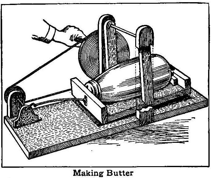
Making Butter
Many people living in a small town or in the suburbs of a city
own one cow that supplies the family table with milk and cream.
Sometimes the cream will accumulate, but not in sufficient
quantities to be made into butter in a large churn. A fruit jar
usually takes the place of a churn and the work is exceedingly
hard, the jar being shaken so the cream will beat against the
ends in the process of butter-making. The accompanying sketch
shows clearly how one boy rigged up a device having a driving
wheel which is turned with a crank, and a driven wheel attached
to an axle having a crank on the inner end. This crank is
connected to a swinging cradle with a wire pitman of such a size
as to slightly bend or spring at each end of the stroke. The
cradle is made with a cleat fastened to each end, between which
is placed the fruit jar, partially filled with cream. The jar is
wedged in between the cleats and the churning effected by turning
the crank.
Contributed by Geo. E. Badger, Mayger, Oregon.
Home-Made Round Swing
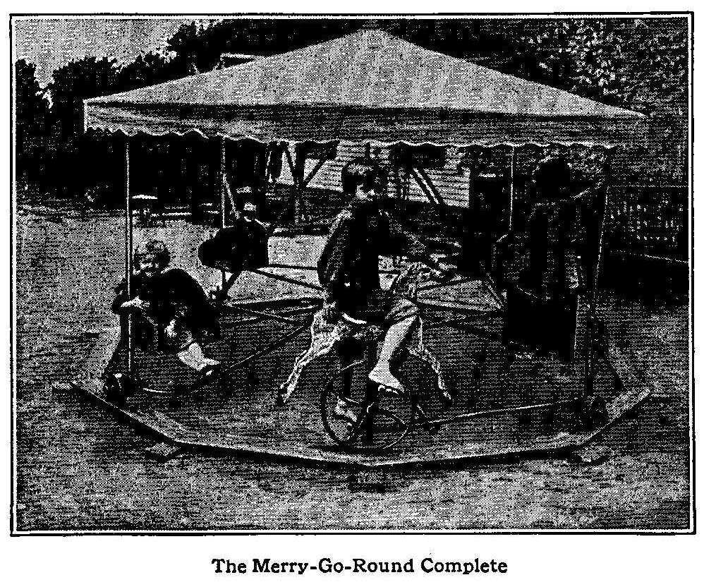
The Merry-Go-Round Complete
Gas pipe and fittings were used wherever possible in the making
of the swing as shown in the photograph. The diagram drawing
shows the construction. A 6-in. square cedar post is set in the
ground about 3 ft., allowing 2 ft. to remain above the ground and
a 7/8-in. piece of shafting is driven into the top part of this
post for an axle. A cast-iron ring, or, better still, a heavy
wheel with four spokes of such a size as to be drilled and tapped
for 1/2-in. pipe is used for the hub, or center on which the
frame swings. If a wheel is selected, the rim must be removed and
only the spokes and hub used. The hole in the hub must be 7/8 in.
or less, so the hub can be fitted to the shafting that is driven
in the post. A large washer is placed on top of the post and the
hub or cast-iron ring set on the washer.
The drilled and tapped holes in the four spokes are each fitted
with a 4-1/2 length of 1/2-in. pipe. These pipes are
each fitted with a tee on the end and into this tee uprights of
1/2-in. pipe in suitable lengths are screwed, and also short
lengths with a tee and axle for the 6-in. wheel are fitted in the
under side of the tee. The uprights at their upper ends are also
fitted with tees and each joined to the center pipe with l/2-in.
pipe flattened on the inner end and fastened with bolts to a
flange.
The bottom part of the cloth covering is held in place by a
1/2-in. pipe, bent to the desired circle. Four braces made from
1/2-in. pipe connect each spoke and seat to the flange on the
center pipe. An extra wheel 18 in. in diameter is fitted in
between two seats and used as the propelling wheel. This wheel
has bicycle cranks and pedals and carries a seat or a hobby
horse. The four seats are fastened to the four pipes with 1/2-in.
pipe clamps.
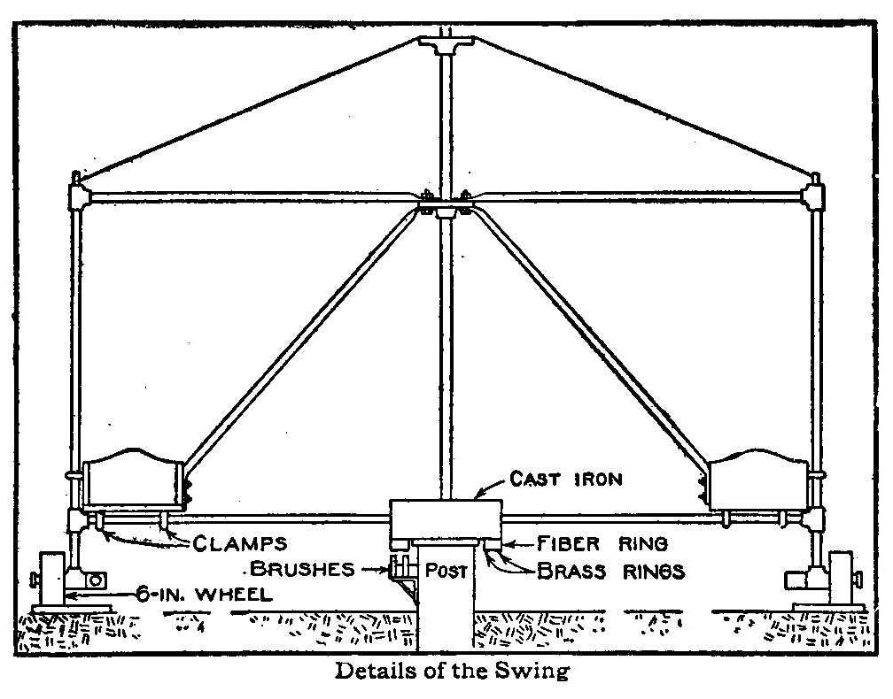
Details of the Swing
Small miniature electric lights are fastened to the overhead
braces and supplied with electric current carried through wires
to the swing by an ingenious device attached to the under side of
the cast-iron ring or hub of the wheel. A ring of fiber on which
two brass rings are attached is fastened to the hub and
connections are made to the two rings through two brushes
fastened to the post with a bracket. The wires run under the
surface of the ground outside and connected to the source of
electricity. The wires from the brass rings run through the
center pipe to the top and are connected to the lamp sockets.
Old-Time Magic-Part V
The Disappearing Coin
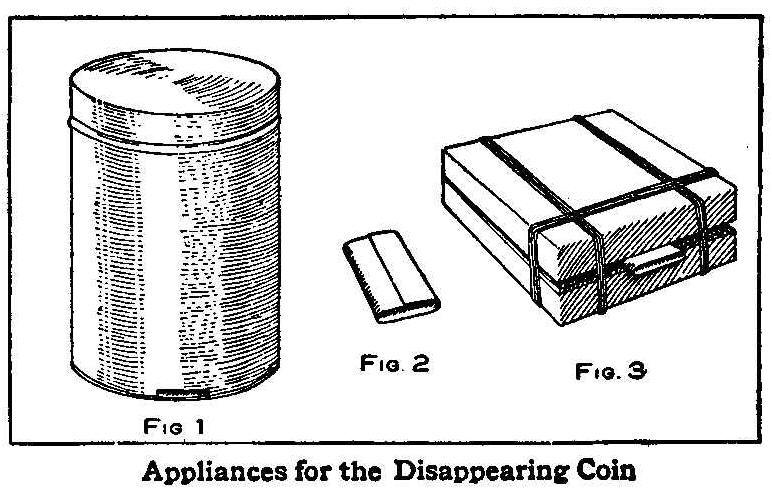
Appliances for the Disappearing Coin
This is an uncommon trick, entirely home-made and yet the results
are as startling as in many of the professional tricks. A small
baking-powder can is employed to vanish the coin, which should be
marked by one of the audience for identification. Cut a slot in
the bottom on the side of the can, as shown in Fig. 1. This slot
should be just large enough for the coin that is used to pass
through freely, and to have its lower edge on a level with the
bottom of the can.
The nest or series of boxes in which the coin is afterwards found
should consist of four small sized flat pasteboard boxes square
or rectangular shaped and furnished with hinged covers. The
smallest need be no larger than necessary to hold the coin and
each succeeding box should be just large enough to hold the next
smaller one which in turn contains the others.
A strip of tin about 1 by 1-3/4 in. is bent in the shape as shown
in Fig. 2 to serve as a guide for the coin through the various
boxes. This guide is inserted about 1/8 in. in the smallest box
between the cover and the box and three rubber bands wrapped
around the box as indicated. This box is then enclosed in the
next larger box, the guide being allowed to project between the
box and the cover, and the necessary tension is secured by three
rubber bands around the box as before. In like manner the
remaining boxes are adjusted so that finally the prepared nest of
boxes appears as in Fig. 3.
The coin can easily be passed into the inner box through the tin
guide, then the guide can be withdrawn which permits the
respective boxes to close and the rubber bands hold each one in a
closed position.
The performer comes forward with the tin can in his right hand,
the bottom of the can in his palm with the slot at the right
side. He removes the cover with the left hand and passes his wand
around the inner part of the can which is then turned upside down
to prove that it contains nothing. The marked coin is dropped
into the can by some one in the audience. The cover is replaced
and the can shaken so the coin will rattle within. The shaking of
the can is continued until the coin has slipped through the slot
into his palm. The can is then placed on the table with his left
hand. Then apparently he looks for something to cover the can.
This is found to be a handkerchief which was previously prepared
on another table concealing the nest of boxes. The coin in the
right hand is quickly slipped into the guide of the nest of
boxes, which was placed in an upright position, and the guide
withdrawn, and dropped on the table. The performer, while doing
this, is explaining that he is looking for a suitable cover for
the can, but as he cannot find one he takes the handkerchief
instead. The handkerchief is spread over the can and then he
brings the nest of boxes. He explains how he will transfer the
coin and passes his wand from the can to the boxes. The can is
then shown to be empty and the boxes given to one in the audience
to be opened. They will be greatly surprised to find the marked
coin within the innermost box.
How to Keep Film Negatives
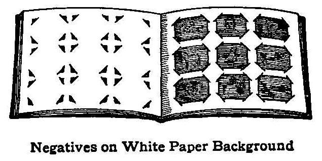
Negatives on White Paper Background
There are many devices for taking care of film negatives to keep
them from curling and in a place easily accessible. Herewith is
illustrated a method by which anyone can make a place for the
negatives produced by his or her special film camera. The device
is made up similar to a post card album with places cut through
each leaf to admit each corner of the negatives. The leaves are
made from white paper and when the negatives are in place the
pictures made on them can easily be seen through to the white
paper background. These leaves can be made up in regular book
form, or tied together similar to a loose-leaf book, thus adding
only such pages as the negatives on hand will require.
Contributed by H. D. Harkins, St. Louis, Mo.
Home-Made Match Safe
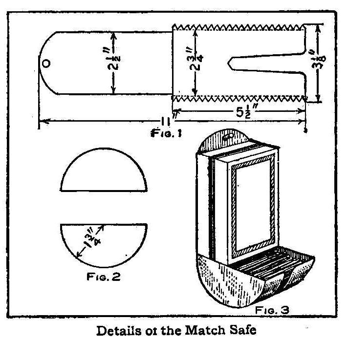
Details of the Match Safe
Cut a piece of tin in the shape and with the dimensions shown in
Fig. 1. Bend the saw-toothed edges at right angles to the piece
on the dotted lines. Bend the part that is marked 5-1/2 in. in a
half circle. Make a circle 3-1/2 in. in diameter on another piece
of tin, cut out the circle and cut the disk in two as shown in
Fig. 2. These half circle pieces are soldered to the sides of the
teeth of the half circle made in the long piece of tin. Remove
one end from the inside box containing matches and slip the back
of the match safe through between the bottom of the inside box
and the open end box that forms the cover. The matches will fall
into the half circle tray at the lower end of the box which will
be kept full of matches until they are all used from the box.
Contributed by C. F. White, Denver, Colo.
An Electric Post Card Projector
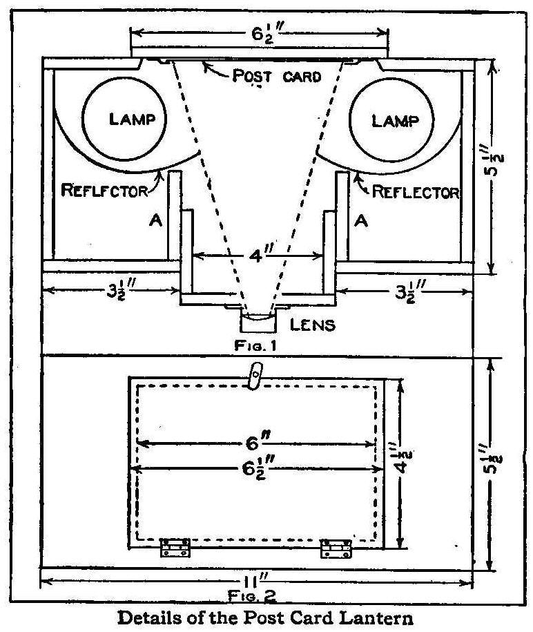
Details of the Post Card Lantern
A post card projector is an instrument for projecting on a screen
in a darkened room picture post cards or any other pictures of a
similar size. The lantern differs from the ordinary magic lantern
in two features; first, it requires no expensive condensing lens,
and second, the objects to be projected have no need of being
transparent.
Two electric globes are made to cast the strongest possible light
on the picture card set between them and in front of which a lens
is placed to project the view on the screen, the whole being
enclosed in a light-tight box. The box can be made of selected
oak or mahogany. The lens to be used as a projector will
determine the size of the box to some extent. The measurements
given in these instructions are for a lens of about 5 in. focal
length. The box should be constructed of well seasoned wood and
all joints made with care so they will be light-tight.
The portion shown carrying the lens in Fig. 1 is made to slide in
the main body of the lantern for focusing. A box should first be
made 5-1/2 in. wide, 5-1/2 in. high and 11 in. long. A hole is
cut in the back of the box 4 by 6 in. represented by the dotted
line in Fig. 2. This will be 3/4 in. from the top and bottom and
2-1/2 in. from each end of the outside of the box. Two strips of
wood 1/2 in. wide and 6-1/2 in. long are fastened along the top
and bottom of the back. The door covering this hole in the back,
and, which is also used as a carrier for the post cards, is made
from a board 4-1/2 in. wide and 6-1/2 in. long. The door is
hinged to the lower strip and held in position by a turn button
on the upper strip. The slides for the picture cards are made
from strips of tin bent as shown, and tacked to the inside
surface of the door.
The runners to hold the part carrying the lens are two pieces
2-1/4 in. wide by 5 in. long and should be placed vertically,
AA, as shown in Fig. 1, 3-1/2 in. from each end. An open space 4
in. wide and 5 in. high in the center is for the part carrying
the lens to slide for focusing. The part carrying the lens is a
shallow box 4 by 5 in. and 2 in. deep in the center of which a
hole is cut to admit the lens. If a camera lens is used, the
flange should be fastened with screws to the front part of this
shallow box. The sides of this box should be made quite smooth
and a good, but not tight, fit into the runners. Plumbago can be
rubbed on to prevent sticking and to dull any rays of light.
Two keyless receptacles for electric globes are fastened to the
under side of the top in the position shown and connected with
wires from the outside. Two or three holes about 1 in. in
diameter should be bored in the top between and in a line with
the lights. These will provide ventilation to keep the pictures
from being scorched or becoming buckled from the excessive
heat. The holes must be covered over on the top with a piece of
metal or wood to prevent the light from showing on the ceiling.
This piece should not be more than 1/2 in. high and must be
colored dead black inside to cause no reflection.
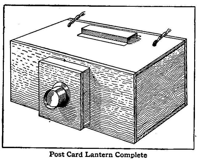
Post Card Lantern Complete
The reflectors are made of sheet tin or nickel-plated metal bent
to a curve as shown, and extending the whole height of the
lantern. The length of these reflectors can be determined by the
angle of the lens when covering the picture. This is clearly
shown by the dotted lines in Fig. 1. The reflectors must not
interfere with the light between the picture and the lens, but
they must be sufficiently large to prevent any direct light
reaching the lens from the lamps. In operation place the post
card upside down in the slides and close the door. Sliding the
shallow box carrying the lens will focus the picture on the
screen.
A Handy Calendar
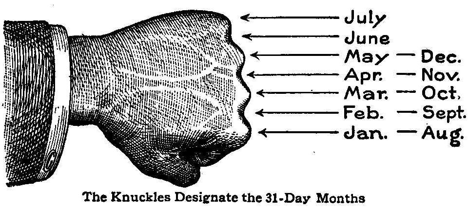
The Knuckles Designate the 31 Day Months
“Thirty days hath September,
April, June and November,” etc.,
and many other rhymes and devices are used to aid the memory to
decide how many days are in each month of the year. Herewith is
illustrated a very simple method to determine the number of days
in any month. Place the first finger of your right hand on the
first knuckle of your left hand, calling that knuckle January;
then drop your finger into the depression between the first and
second knuckles, calling this February; then the second knuckle
will be March, and so on, until you reach July on the knuckle of
the little finger, then begin over again with August on the first
knuckle and continue until December is reached. Each month as it
falls upon a knuckle will have 31 days and those down between the
knuckles 30 days with the exception of February which has only 28
days.
Contributed by Chas. C. Bradley, West Toledo, Ohio.
The Fuming of Oak
Darkened oak always has a better appearance when fumed with
ammonia. This process is rather a difficult one, as it requires
an airtight case, but the description herewith given may be
entered into with as large a case as the builder cares to
construct.
Oak articles can be treated in a case made from a tin biscuit
box, or any other metal receptacle of good proportions, provided
it is airtight. The oak to be fumed is arranged in the box so the
fumes will entirely surround the piece; the article may be
propped up with small sticks, or suspended by a string. The chief
point is to see that no part of the wood is covered up and that
all surfaces are exposed to the fumes. A saucer of ammonia is
placed in the bottom of the box, the lid or cover closed, and all
joints sealed up by pasting heavy brown paper over them. Any
leakage will be detected if the nose is placed near the tin and
farther application of the paper will stop the holes. A hole may
be cut in the cover and a piece of glass fitted in, taking care
to have all the edges closed. The process may be watched through
the glass and the article removed when the oak is fumed to the
desired shade. Wood stained in this manner should not be French
polished or varnished, but waxed.
The process of waxing is simple: Cut some beeswax into fine
shreds and place them in a small pot or jar. Pour in a little
turpentine, and set aside for half a day, giving it an occasional
stir. The wax must be thoroughly dissolved and then more
turpentine added until the preparation has the consistency of a
thick cream. This can be applied to the wood with a rag and
afterward brushed up with a stiff brush.
How to Make an Electrolytic Rectifier
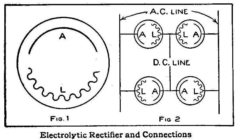
Electrolytic Rectifier and Connections
Many devices which will change alternating current to a direct
current have been put on the market, but probably there is not
one of them which suits the amateur’s needs and pocketbook better
than the electrolytic rectifier.
For the construction of such a rectifier four 2-qt. fruit jars
are required. In each place two electrodes, one of
lead and one
of aluminum. The immersed surface of the aluminum should be about
15 sq. in. and the lead 24 sq. in.
The immersed surface of the
lead being greater than
that of the aluminum, the lead will have
to be crimped as shown in Fig, 1. In both Fig. 1 and 2,
the lead
is indicated by L and the aluminum by A.
The solution with which each jar is to be filled consists of the
following:
| Water | 2 qt. |
| Sodium Carbonate | 2 tablespoonfuls |
| Alum | 3 tablespoonfuls |
Care should be taken to leave the connections made as shown in
Fig. 2. The alternating current comes in on the wires as shown,
and the direct current is taken from the point indicated.
The capacity of this rectifier is from 3 to 5 amperes, which is
sufficient for charging small storage batteries, running small
motors and lighting small lamps.
Contributed by J. H. Crawford, Schenectady, N. Y.
The Rolling Marble
Take a marble and place it on a smooth surface, The top of a
table will do. Ask someone to cross their first and second
fingers and place them on the marble as shown in the
illustration. Then have the person roll the marble about and at
the same time close the eyes or look in another direction. The
person will imagine that there are two marbles instead of one.
A Gas Cannon
Gas Cannon Loaded
If you have a small cannon with a bore of 1 or 1-1/2 in., bore
out the fuse hole large enough to tap and fit in a small sized
spark plug such as used on a gasoline engine. Fill the cannon
with gas from a gas jet and then push a cork in the bore close up
to the spark plug. Connect one of the wires from a battery to a
spark coil and then to the spark plug. Attach the other wire to
the cannon near the spark plug. Turn the switch to make a spark
and a loud report will follow.
Contributed by Cyril Tegner, Cleveland, O.
Old-Time Magic-Part VI
A Handkerchief Mended after Being Cut and Torn
Two persons are requested to come forward from the audience to
hold the four corners of a handkerchief. Then beg several other
handkerchiefs from the audience and place them on the one held by
the two persons. When several handkerchiefs have been
accumulated, have some one person draw out one from the bunch and
examine for any marks that will determine that this handkerchief
is the one to be mended after being mutilated. He, as well as
others, are to cut off pieces from this handkerchief and to
finally tear it to pieces.
The pieces are then all collected and some magic spirits thrown
over the torn and cut parts; tie them in a small package with a
ribbon and put them under a glass, which you warm with your
hands. After a few seconds’ time, you remove the glass, as you
have held it all the time, and take the handkerchief and unfold
it; everyone will recognize the mark and be amazed not to find
a cut or tear in the texture.
This trick is very simple. You have an understanding with some
one in the company, who has two handkerchiefs exactly alike and
has given one of them to a person behind the curtain; he throws
the other, at the time of request for handkerchiefs, on the
handkerchiefs held for use in the performance of the trick. You
manage to keep this handkerchief where it will be picked out in
preference to the others, although pretending to thoroughly mix
them up. The person selected to pick out a handkerchief naturally
will take the handiest one. Be sure that this is the right one.
When the handkerchief has been torn and folded, put it under the
glass, on a table, near a partition or curtain. The table should
be made with a hole cut through the top and a small trap door
fitted snugly in the hole, so it will appear to be a part of the
table top. This trap door is hinged on the under side and opens
into the drawer of the table and can be operated by the person
behind the curtain who will remove the torn handkerchief and
replace it with the good one and then close the trap door by
reaching through the drawer of the table.
The Magic Knot
Tying and Untying a Knot
This is a very amusing trick which consists of tying one knot
with two ends of a handkerchief, and pulling the ends only to
untie them again. Take the two diagonal corners of a
handkerchief, one in each hand and throw the main part of the
handkerchief over the wrist of the left hand and tie the knot as
shown in the illustration. Pull the ends quickly, allowing the
loop over the left hand to slip freely, and you will have the
handkerchief without any knot.
A Good Mouse Trap
When opening a tomato or other small can, cut the cover crossways
from side to side making four triangular pieces in the top. Bend
the four ends outward and remove the contents, wash clean and dry
and then bend the four ends inward, leaving a hole about 3/4 in.
in diameter in the center. Drop in a piece of bread and lay the
can down upon its side and the trap is ready for use. The mouse
can get in but he cannot get out.
Contributed by E. J. Crocker, Victor, Colo.
Finishing Aluminum
Rubbing the surface of an aluminum plate with a steel brush will
produce a satin finish.
How to Make a Sailing Canoe
Completed Sailing Canoe
A canvas canoe is easily made and light to handle, but in making
one, it must be remembered that the cloth will tear, if any snags
are encountered. Therefore such a craft cannot be used in all
waters, but by being careful at shores, it can be used as safely
as an ordinary sailing canoe. Be sure to select the best
materials and when complete cover the seams well with paint.
The materials necessary for the construction of a sailing canoe,
as illustrated in the engraving, are as follows:
1 keelson, 1 in. by 8 in. by 15 ft., selected pine.
14 rib bands, 1 in. square by 16 ft., clear pine.
2 gunwales, 1 in. by 2 in. by 16 ft.
1 piece for forms and bow pieces, 1 in. by 12 in. by 10 ft.
4 outwales, 1/4 in. by 2 in. by 16 ft.
1 piece, 3 in. wide and 12 ft. long, for cockpit frame.
1 piece, 2 in. wide and 12 ft. long, for center deck braces.
11 yd. of 1-1/2-yd. wide 12-oz. ducking.
8 yd. of 1-yd. wide unbleached muslin.
50 ft. of rope.
1 mast, 9 ft. long.
Paint, screws and cleats.
The keelson, Fig. 1, is 14 ft. long, 8 in. wide in the center and
tapered down from a point 4 ft. from each end to 1 in. at the
ends. Both ends are mortised, one 6 in. for the stern piece, and
the other 12 in. for the bow. Be sure to get the bow and stern
pieces directly in the middle of the keelson and at right angles
with the top edge. The stern and bow pieces are cut as shown in
Fig. 2 and braced with an iron band, 1/8 in. thick and 3/4 in.
wide, drilled and fastened with screws.
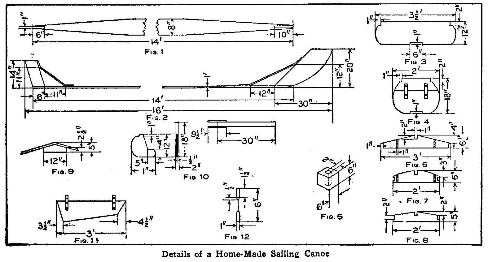
Details of a Home-Made Sailing Canoe
Study the sketches showing the details well before starting to
cut out the pieces. Then there will be no trouble experienced
later in putting the parts together. See that all the pieces fit
their places as the work proceeds and apply the canvas with care.
Two forms are made as shown in Figs. 3 and 4; the smaller is
placed 3 ft. from the bow and the large one, 7 ft. 3 in. from the
stern. The larger mould is used temporarily while making the
boat, and is removed after the ribs are in place. The gunwales
are now placed over the forms and in the notches shown, and
fastened with screws, and, after cutting the ends to fit the bow
and stern pieces, they are fastened with bolts put through the
three pieces. The sharp edges on one side of each rib-band are
removed and seven of them fastened with screws to each side of
the moulds, spacing them on the large mould 4 in. apart. The ribs
are made of 28 good barrel hoops
which should be well soaked in water for several hours before
bending them in shape. These are put in 6 in. apart and are
fastened to the rib-bands with 7/8-in. wood screws. The ribs
should be put in straight and true to keep them from pulling the
rib-bands out of shape. After the ribs are in place and fastened
to the rib-bands, gunwales and keelson, put on the outwale strips
and fasten them to the gunwales between every rib with 1-1/2-in.
screws.
Before making the deck, a block for the mast to rest in must be
made and fastened to the keelson. This block, Fig. 5, is a cube
having sides 6 in. square and is kept from splitting by an iron
band tightly fitted around the outside. The block is fastened to
the keelson, 3-1/2 ft. from the bow, with bolts through
countersunk holes from the under side.
There are three deck braces made as shown in Figs. 6, 7 and 8.
Braces, Figs. 6 and 7, form the ends of the cockpit which is 20
in. wide. A 6-in. board is fitted into the mortises shown in
these pieces; a center piece is fitted in the other mortises. The
other deck braces slope down from the center piece and are placed
6 in. apart. They are 1 in. square and are mortised into the
center piece and fastened to the gunwales with screws. The main
deck braces are fastened to the gunwales with 4-in. corner braces
and to the center piece with 2-in. corner braces. The mast hole
on the deck is made as follows: Secure a piece of pine 1 in.
thick, 6 in. wide and 3 ft. long. Cut this in halves and mortise
for the center piece in the two halves and fasten to the
gunwales. A block of pine, 4 in. thick and 12 in. long, is cut to
fit under the top boards, Fig. 9, and fastened to them with
bolts. With an expansive bit bore a hole 3 in. in diameter
through the block. Be sure to get the block and hole directly
over the block that is fastened to the keelson. Put on a coat of
boiled linseed oil all over the frame before proceeding farther.
Putting on the canvas may be a difficult piece of work to do, yet
if the following simple directions are followed out no trouble
will be encountered. The 11-yd. length of canvas is cut in the
center, doubled, and a seam made joining the two pieces together.
Fill the seam with thick paint and tack it down with copper tacks
along the center of the keelson. When this is well tacked
commence stretching and pulling the canvas in the middle of the
gunwales so as to make it as even and tight as possible and work
toward each end, tacking the canvas as it is stretched to the
outside of the gunwale. Seam the canvas along the stern and bow
pieces as was done on the keelson. The deck is not so hard to do,
but be careful to get the canvas tight and even. A seam should be
made along the center piece. The trimming is wood, 1/4 in. thick
and 1/2 in. wide. A strip of this is nailed along the center
piece over the canvas. The outwales are nailed on over the
canvas. A piece of oak, 1 in. thick 1-1/2 in. wide and 14 in.
long, is fastened with screws over the canvas on the stern piece;
also, a piece 1/4 in. thick, 1 in. wide and 24 in. long is well
soaked in water, bent to the right shape and fastened over the
canvas on the bow.
The rudder is made as shown in Fig. 10 with a movable handle. A
strip 1 in. thick by 2 in. wide, is bolted to the keelson over
the canvas for the outer keel. The keel, Fig. 11, is 6 in. wide
at one end and 12 in. at the other, which is fastened to the
outer keel with bolts having thumb nuts. The mast can be made of
a young spruce tree having a diameter of 3 in. at the base with
sufficient height to make it 9 ft. long. The canoe is driven by a
lanteen sail and two curtain poles, each 1 in. in diameter and 10
ft. long, are used for the boom and gaff, which are held together
with two pieces of iron bent as shown in Fig. 12. The sail is a
triangle, 9-3/4 by 9-3/4 by 8-1/2 ft. which is held to the boom
and gaff by cord lacings run through eyelets inserted in the
muslin. The eyelets are of brass placed 4 in. apart in the
muslin. The mast has two side and one front stay, each fitted
with a turnbuckle for tightening. A pulley is placed at the top
and bottom of the mast for the lift rope. The sail is held to the
mast by an iron ring and the lift rope at the top of the mast.
The boom rope is held in the hand and several cleats should be
placed in the cockpit for convenience. A chock is placed at the
bow for tying up to piers. Several coats of good paint complete
the boat.
Contributed by O. E. Tronnes, Wilmette, Ill.
A Home-Made Hand Vise
Hand Vise Made from a Hinge
A very useful little hand vise can easily be made from a hinge
and a bolt carrying a wing nut. Get a fast joint hinge about 2
in. or more long and a bolt about 1/2 in. long that will fit the
holes in the hinge. Put the bolt through the middle hole of the
hinge and replace the nut as shown in the drawing. With this
device any small object may be firmly held by simply placing it
between the sides of the hinge and tightening the nut.
Proper Design for a Bird House
This bird house was designed and built to make a home for the
American martin. The house will accommodate 20 families. All the
holes are arranged so they will not be open to the cold winds
from the north which often kill the birds which come in the early
spring. Around each opening is an extra ring of wood to make a
longer passage which assists the martin inside in fighting off
the English sparrow who tries to drive him out. The holes are
made oval to allow all the little ones to get their heads out for
fresh air. The long overhanging eaves protect the little birds
from the hot summer sun.
The rooms are made up with partitions on the inside so each
opening will have a room. The inside of the rooms should be
stained black.
Boomerangs and How to Make Them
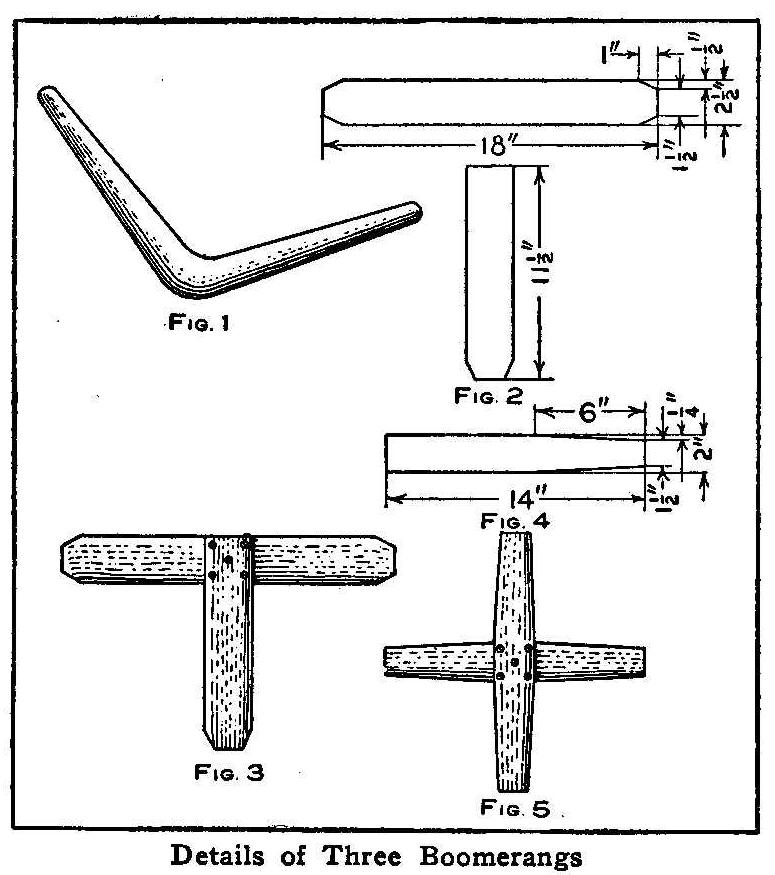
Details of Three Boomerangs
A boomerang is a weapon invented and used by the native
Australians, who seemed to have the least intelligence of any
race of mankind. The boomerang is a curved stick of hardwood,
Fig. 1, about 5/16 in. thick, 2-1/2 in. wide and 2 ft. long, flat
on one side, with the ends and the other side rounding. One end
of the stick is grasped in one hand with the convex edge forward
and the flat side up and thrown upward. After going some distance
and ascending slowly to a great height in the air with a quick
rotary motion, it suddenly returns in an elliptical orbit to a
spot near the starting point. If thrown down on the ground the
boomerang rebounds in a straight line, pursuing a ricochet motion
until the object is struck at which it was thrown.
Two other types of boomerangs are illustrated herewith and they
can be made as described. The materials necessary for the
T-shaped boomerang are: One piece of hard maple 5/16 in. thick,
2-1/2 in. wide, and 3 ft. long; five 1/2-in. flat-headed screws.
Cut the piece of hard maple into two pieces, one 11-1/2 in. and
the other 18 in. long. The corners are cut from these pieces as
shown in Fig. 2, taking care to cut exactly the same amount from
each corner. Bevel both sides of the pieces, making the edges
very thin so they will cut the air better. Find the exact center
of the long piece and make a line 1-1/4 in. on each side of the
center and fasten the short length between the lines with the
screws as shown in Fig. 3. The short piece should be fastened
perfectly square and at right angles to the long one.
The materials necessary for the cross-shaped boomerang are one
piece hard maple 5/16 in. thick, 2 in. wide and 30 in. long and
five 1/2-in. flat headed screws. Cut the maple into two 14-in.
pieces and plane the edges of these pieces so the ends will be
1-1/2 in. wide, as shown in Fig. 4. Bevel these pieces the same
as the ones for the T-shaped boomerang. The two pieces are
fastened together as shown in Fig. 5. All of the boomerangs when
completed should be given several coats of linseed oil and
thoroughly dried. This will keep the wood from absorbing water
and becoming heavy. The last two boomerangs are thrown in a
similar way to the first one, except that one of the pieces is
grasped in the hand and the throw given with a quick underhand
motion. A little practice is all that is necessary for one to
become skillful in throwing them.
Contributed by O. E. Tronnes, Wilmette, Ill.
How to Make Water Wings
Purchase a piece of unbleached muslin, 1 yd. square. Take this
and fold it over once, forming a double piece 1-1/2 ft. wide and
3 ft. long. Make a double stitch all around the edge, leaving a
small opening at one corner. Insert a piece of tape at this
corner to be used for tying around the opening when the bag is
blown up. The bag is then turned inside out, soaked with water
and blown up. An occasional wetting all over will prevent it from
leaking. As these wings are very large they will prevent the
swimmer from sinking.
Contributed by W. C. Bliss, St. Louis, Mo.
How to Make an Ammeter
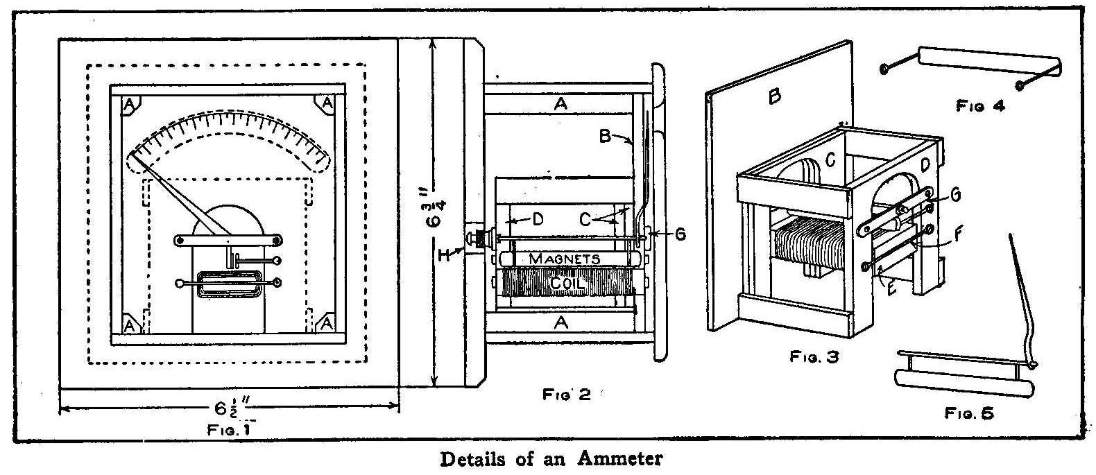
Details of an Ammeter
The outside case of this instrument is made of wood taken from
old cigar boxes with the exception of the back. If carefully and
neatly made, the finished instrument will be very satisfactory.
The measurements here given need not be strictly followed out,
but can be governed by circumstances. The case should first be
made and varnished and while this is drying, the mechanical parts
can be put together.
The back is a board 3/8 in. thick, 6-1/2 in. wide and 6-3/4 in.
long. The outer edges of this board are chamfered. The other
parts of the case are made from the cigar box wood which should
be well sandpapered to remove the labels. The sides are 3-1/4 in.
wide and 5 in. long; the top and bottom, 3-1/4 in. wide and 4-1/2
in. long. Glue a three cornered piece, A, Fig. 1, at each end on
the surface that is to be the inside of the top and bottom
pieces. After the glue, is set, fasten the sides to the pieces
with glue, and take care that the pieces are all square. When the
glue is set, this square box is well sandpapered, then centered,
and fastened to the back with small screws turned into each
three-cornered piece.
The front, which is a piece 5-1/4 in. wide and 6-1/2 in. long,
has a circular opening cut near the top through which the
graduated scale may be seen. This front is centered and fastened
the same as the back, and the four outside edges, as well as the
edges around the opening, are rounded. The whole case can now be
cleaned and stained with a light mahogany stain and varnished.
Cut another piece of board, B, Figs. 2 and 3, to just fit inside
the case and rest on the ends of the three-cornered pieces, A,
and glue to this board two smaller pieces, C, 3 in. square, with
the grain of the wood in alternate directions to prevent warping.
All of these pieces are made of the cigar box wood. Another
piece, D, 3/8 in. thick and 3 in. square, is placed on the other
pieces and a U-shaped opening 1-3/4 in. wide and 2-1/2 in. high
sawed out from all of the pieces as shown. The piece D is
attached to the pieces C with four 1/2-in. pieces 2-5/8 in. long.
A magnet is made from a soft piece of iron, E, about 3/8 in.
thick, 1-1/4 in. wide and 2-3/4 in. long. Solder across each end
of the iron a piece of brass wire, F, and make a turn in each end
of the wires, forming an eye for a screw. These wires are about
2-1/2 in. long. Wind three layers of about No. 14 double
cotton-covered copper wire on the soft iron and leave about 5 or
6 in. of each end unwound for connections. The pointer is made as
shown in Fig. 5 from 1/16-in. brass wire filed to make a point at
both ends for a spindle. About 1/2 in. from each end of this
wire are soldered two smaller brass wires which in turn are
soldered to a strip of light tin 1/4 in. wide and 2-5/8 in. long.
The lower edge of this tin should be about 1/2 in. from the
spindle.
The pointer is soldered to the spindle 1/4 in. from one end. All
of these parts should be brass with the exception of the strip of
tin. Another strip of tin, the same size as the first, is
soldered to two brass wires as shown in Fig. 4. These wires
should be about 1 in. long.
The spindle of the pointer swings freely between two bars of
brass, G, 1/16 in. thick, 1/4 in. wide and 2-1/2 in. long. A
small hole is countersunk in one of the bars to receive one end
of the spindle and a hole 1/8 in. in diameter is drilled in the
other and a thumb nut taken from the binding-post of an old
battery soldered over the hole so the screw will pass through
when turned into the nut. The end of the screw is countersunk to
receive the other end of the spindle. A lock nut is necessary to
fasten the screw when proper adjustment is secured. A hole is
drilled in both ends of the bars for screws to fasten them in
place. The bar with the adjusting screw is fastened on the back
so it can be readily adjusted through the hole H, bored in the
back. The pointer is bent so it will pass through the U-shaped
cut-out and up back of the board B. A brass pin is driven in the
board B to hold the pointer from dropping down too far to the
left. Place the tin, Fig. 4, so it will just clear the tin, Fig.
5, and fasten in place. The magnet is next placed with the ends
of the coil to the back and the top just clearing the tin strips.
Two binding screws are fitted to the bottom of the back and
connected to the extending wires from the coil.
The instrument is now ready for calibrating. This is done by
connecting it in series with another standard ammeter which has
the scale marked in known quantities. In this series is also
connected a variable resistance and a battery or some other
source of current supply. The resistance is now adjusted to show
.5 ampere on the standard ammeter and the position of the pointer
marked on the scale. Change your resistance to all points and
make the numbers until the entire scale is complete.
When the current flows through the coil, the two tinned strips of
metal are magnetized, and being magnetized by the same lines of
force they are both of the same polarity. Like poles repel each
other, and as the part Fig. 4 is not movable, the part carrying
the pointer moves away. The stronger the current, the greater the
magnetism of the metal strips, and the farther apart they will be
forced, showing a greater defection of the pointer.
Contributed by George Heimroth, Richmond Hill, L. I.
How to Make an Equatorial
Condensed from article contributed by J. R. Chapman, F.R.A.S.
Austwick Hall. W. Yorkshire. England
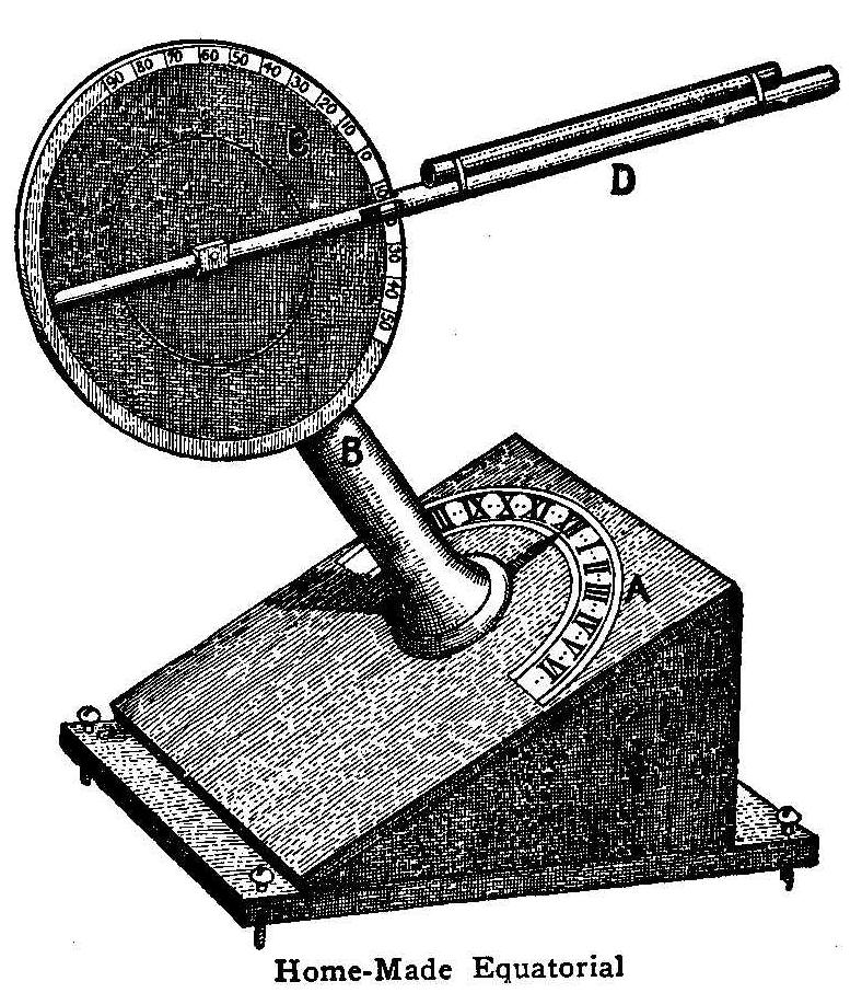
Home-Made Equatorial
This star finder can easily be made by anyone who can use a few
tools as the parts are all wood and the only lathe work necessary
is the turned shoulder on the polar axis and this could be
dressed and sandpapered true enough for the purpose. The base is
a board 5 in. wide and 9 in. long which is fitted with an
ordinary wood screw in each corner for leveling. Two side pieces
cut with an angle equal to the colatitude of the place are nailed
to the base and on top of them is fastened another board on which
is marked the hour circle as shown. The end of the polar axis B,
that has the end turned with a shoulder, is fitted in a hole
bored in the center of the hour circle. The polar axis B is
secured to the board with a wooden collar and a pin underneath.
The upper end of the polar axis is fitted with a 1/4-in. board,
C, 5-1/2 in. in diameter. A thin compass card divided into
degrees is fitted on the edge of this disk for the declination
circle.
{205}
The hour circle A is half of a similar card with the hour marks
divided into 20 minutes. An index pointer is fastened to the base
of the polar axis. A pointer 12 in. long is fastened with a small
bolt to the center of the declination circle. A small opening is
made in the pointer into which an ordinary needle is inserted.
This needle is adjusted to the degree to set the pointer in
declination and when set, the pointer is clamped with the bolt at
the center. A brass tube having a 1/4-in. hole is fastened to the
pointer.
The first thing to do is to get a true N and S meridian mark.
This can be approximately obtained by a good compass, and
allowance made for the magnetic declination at your own place.
Secure a slab of stone or some other solid flat surface, level
this and have it firmly fixed facing due south with a line drawn
through the center and put the equatorial on the surface with XII
on the south end of the line. Then set the pointer D to the
declination of the object, say Venus at the date of observation.
You now want to know if this planet is east or west of your
meridian at the time of observation. The following formula will
show how this may be found. To find a celestial object by
equatorial: Find the planet Venus May 21, 1881, at 9 hr. 10 min.
A. M. Subtract right ascension of planet from the time shown by
the clock, thus:
| hour | minute | second | |
| 9 hr. 10 min. shows mean siderial. | 1 | 0 | 0 |
| Add 12 hrs | 12 | 0 | 0 |
| — | — | — | |
| 13 | 0 | 0 | |
| Right ascension of Venus | 2 | 10 | 0 |
| — | — | — | |
| Set hour circle to before meridian | 10 | 50 | 0 |
| hour | minute | second | |
| At 1 hr. 30 min. mean clock shows | 5 | 20 | 0 siderial |
| Right ascension of Venus | 2 | 10 | 0 |
| — | — | — | |
| Set hour circle to | 3 | 10 | 0 |
Books may be found in libraries that will give the right
ascension and declination of most of the heavenly bodies.
The foregoing tables assume that you have a clock rated to
siderial time, but this is not absolutely necessary. If you can
obtain the planet’s declination on the day of observation and
ascertain when it is due south, all you have to do is to set the
pointer D by the needle point and note whether Venus has passed
your meridian or not and set your hour index. There will be no
difficulty in picking up Venus even in bright sunlight when the
planet is visible to the naked eye.
Electric Light Turned On and Off from Different Places
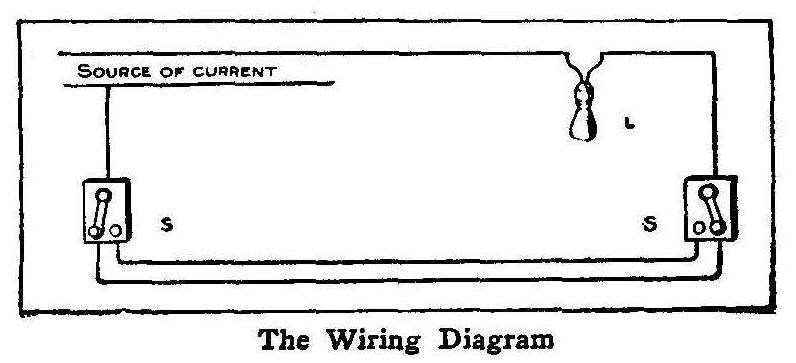
The Wiring Diagram
How nice it would be to have an electric light at the turn in a
stairway, or at the top that could be turned on before starting
up the stair and on reaching the top turned out, and vice versa
when coming down. The wiring diagram as shown in the illustration
will make this a pleasant reality. This wiring may be applied in
numerous like instances. The electric globe may be located at any
desired place and the two point switches are connected in series
with the source of current as shown in the sketch. The light may
be turned on or off at either one of the switches.
Contributed by Robert W. Hall, New Haven, Conn.
Optical Illusion
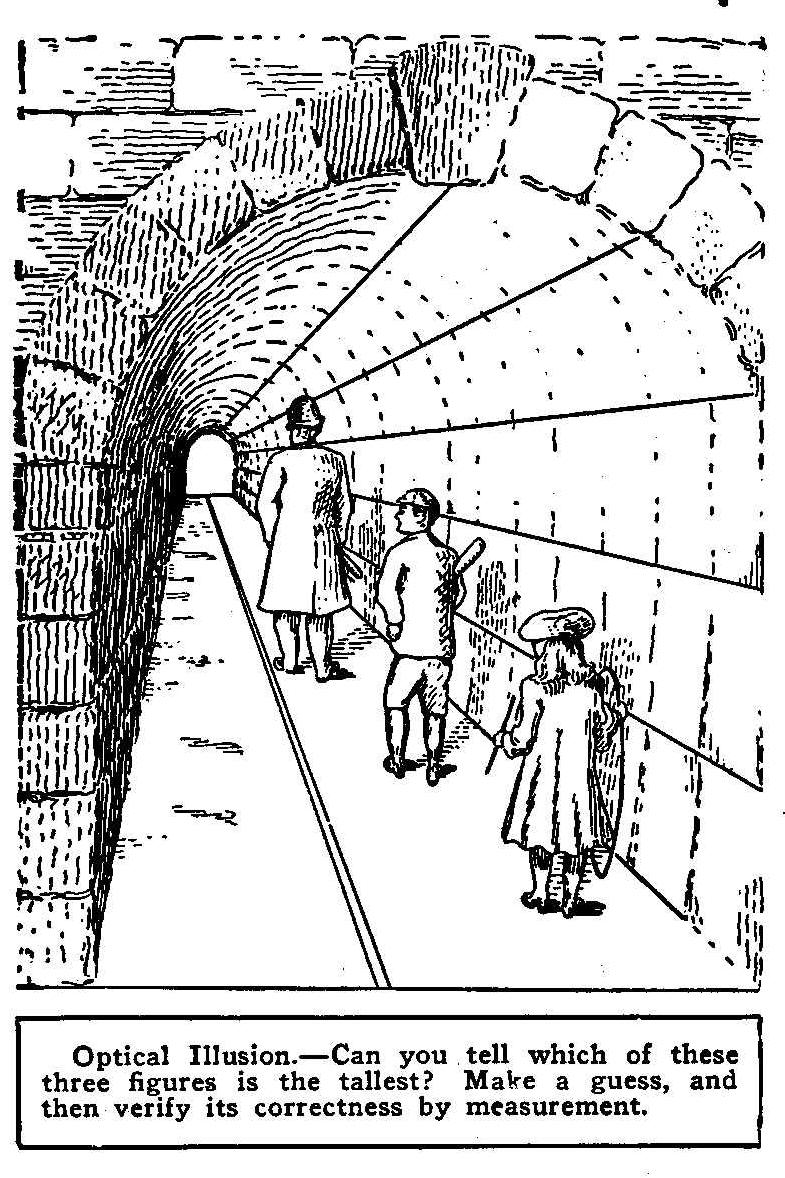
guess, and then verify its correctness by measurement.
How to Make a Bunsen Cell
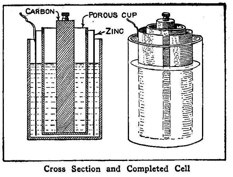
Cross Section and Completed Cell
This kind of a cell produces a high e.m.f. owing to the low
internal resistance. Procure a glass jar such as used for a
gravity battery, or, if one of these cannot be had, get a glazed
vessel of similar construction. Take a piece of sheet zinc large
enough so that when it is rolled up in the shape of a cylinder it
will clear the edge of the jar by about 1/2 in. Solder a wire or
binding-post to the edge of the cylinder for a connection. Secure
a small unglazed vessel to fit inside of the zinc, or such a
receptacle as used in a sal ammoniac cell, and fill it with a
strong solution of nitric acid.
Fill the outer jar with a
solution of 16 parts water and 5 parts
sulphuric acid. The
connections are made from the zinc and carbon.
One Way to Cook Fish
One of the best and easiest ways of cooking fish while out
camping is told by a correspondent of Forest and Stream. A fire
is built the size for the amount of food to be cooked and the
wood allowed to burn down to a glowing mass of coals and ashes.
Wash and season your fish well and then wrap them up in clean,
fresh grass, leaves or bark. Then, after scraping away the
greater part of the coals, put the fish among the ashes, cover up
with the same, and heap the glowing coals on top. The fish cooks
quickly—15 or 20 minutes—according to their size.
If you eat fish or game cooked after this fashion you will agree
that it cannot be beaten by any method known to camp culinary
savants. Clay also answers the purpose of protecting the fish or
game from the fire if no other material is at hand, and for
anything that requires more time for cooking it makes the best
covering. Wet paper will answer, especially for cooking fish.
Hardening Copper
A successful method of hardening copper is to add 1 lb. of alum
and 4 oz. arsenic
to every 20 lb. of melted copper and stir for 10 minutes.
Packing Cut from Felt Hats
Felt from an old hat makes good packing for automobile
water-circulating pumps. Strips should be cut to fit snugly in
the stuffing box. When the follower is screwed down, it will
expand the felt and make a watertight joint.
Homemade Gasoline Engine
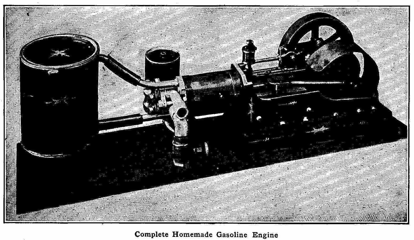
Complete Homemade Gasoline Engine
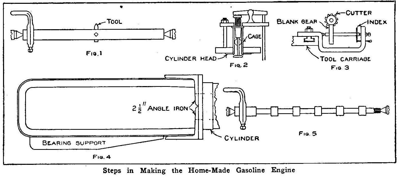
Steps in Making the Home-Made Gasoline Engine
The material used in the construction of the gasoline engine, as
shown in the accompanying picture, was pieces found in a scrap
pile that usually occupies a fence corner on almost every farm.
The cylinder consists of an old pump cylinder, 3/8 in. thick,
1-3/4 in. inside diameter and about 5 in. long. This was fastened
between some wooden blocks which were bolted on the tool carriage
of a lathe and then bored out to a diameter of about 2 in. The
boring bar, Fig. 1, consisted of an old shaft with a hole bored
through the center and a tool inserted and held for each cut by a
setscrew. A wood mandrel with a metal shaft to turn in the
centers of a lathe was made to fit the bored-out cylinder. The
cylinder was then placed on the mandrel, fastened with a pin, and
threaded on both ends. Flanges were next made from couplings
discarded from an old horsepower tumbling rod, to fit on the
threaded ends of the cylinder casting. When these flanges were
tightly screwed on the casting and faced off smooth the whole
presented the appearance of a large spool.
The back cylinder head was made from a piece of cast iron, about
1/2 in. thick, turned to the same diameter as the flanges, and
with a small projection to fit snugly inside the cylinder bore.
Two holes were then drilled in this head and tapped for 3/4-in.
pipe. Two pieces of 3/4-in. pipe were fitted to these holes so
that, when they were turned in, a small part of the end of each
pipe projected on the inside of the cylinder head. These pieces
of pipe serve as valve cages and are reamed out on the inside
ends to form a valve seat. The outlet for the exhaust and the
inlet for the gas and air are through holes drilled in the side
of each pipe respectively and tapped for 1/2-in. pipe. Two heads
were then made to fit over the outer ends of the valve cages.
These heads looked similar to a thread spool with one flange cut
off, the remaining flange fitting on the end of the valve cage
and the center extending down inside to make a long guide for the
valve stems. These heads are held in place by a wrought-iron
plate and two bolts, one of which is plainly shown in the
picture. This plate also supports the rocker arms, Fig. 2, and
the guides for the rods that operate the valves. Both valves are
mechanically operated by one cam attached to a shaft running
one turn to two of the crankshaft. The gears to run this shaft
were cut from solid pieces on a small home-made gear-cutting
attachment for the lathe as shown in Fig. 3. The gear on the
crankshaft has 20 teeth meshing into a 40-tooth gear on the cam
shaft.
The main part of the frame consists of a piece of 1/2-in. square
iron, 30 in. long, bent in the shape of a U, and on the outside
of this piece is riveted a bent piece of sheet metal 1/8 in.
thick and 3 in. wide. The U-shaped iron is placed near one edge
of the sheet metal. Two pieces of 2-1/2-in. angle iron are
riveted vertically on the ends of the U-shaped iron and a plate
riveted on them to close the open end and to form a face on which
to attach the cylinder with bolts or cap screws. A hole was cut
through the angle irons and plate the same size as the bore of
the cylinder so the piston could be taken out without removing
the cylinder. A 1-in. angle iron was riveted to one side of the
finished frame to make a support for the crankshaft bearing. The
rough frame, Fig. 4, was then finished on an emery wheel. This
long frame had to be made to accommodate the crosshead which was
necessary for such a short cylinder.
The piston and rod were screwed together and turned in one
operation on a lathe. The three rings were made from an old
cast-iron pulley. The cap screws were made from steel pump rods.
A piece of this rod was centered in a lathe and turned so as to
shape six or more screws, Fig. 5, then removed and the first one
threaded and cut off, then the second and so on until all of them
were made into screws. The rod was held in a vise for this last
operation. Studs were made by threading both ends of a proper
length rod. Make-and-break ignition is used on the engine;
however, a jump spark would be much better. The flywheel and
mixing valve were purchased from a house dealing in these parts.
The water jacket on the cylinder is a sheet of copper formed and
soldered in place, and brass bands put on to cover the
soldered joints.
Contributed by Peter J. Johnson, Clermont, Iowa.
Dripping Carburetor
If gasoline drips from the carburetor when the engine is not
running, the needle valve connected with the float should be
investigated. If the dripping stops when the valve is pressed
down, the float is too high. If the valve keeps dripping, then it
should be ground to a fit.
A Merry-Go-Round Thriller
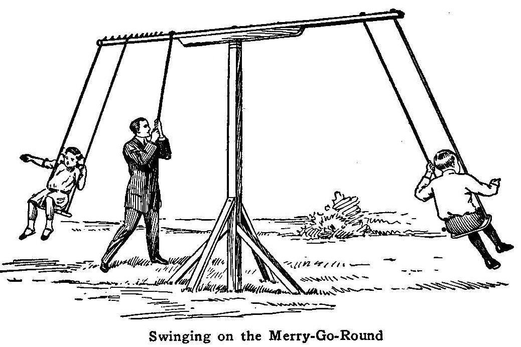
Swinging on the Merry-Go-Round
As a home mechanic with a fondness for amusing the children I
have seen many descriptions of merry-go-rounds, but never one
which required so little material, labor and time, and which gave
such satisfactory results, as the one illustrated herewith. It
was erected in our back yard one afternoon, the materials being
furnished by an accommodating lumber pile, and a little junk, and
it has provided unlimited pleasure for “joy-riders,” little and
big, from all over the neighborhood. It looks like a toy, but
once seat yourself in it and begin to go around, and, no matter
what your age or size may be, you will have in a minute enough
thrill and excitement to last the balance of the day.
The illustration largely explains itself, but a few dimensions
will be a help to anyone wishing to construct the apparatus. The
upright is a 4 by 4-in. timber, set 3 ft. in the ground with 8
ft. extending above. It is braced on four sides with pieces 2 in.
square and 2 ft. long, butting against short stakes. The upper
end of the post is wound with a few rounds of wire or an iron
strap to prevent splitting. The crosspiece is 2 in. square, 12
ft. long, strengthened by a piece 4 in. square and 5 ft. long.
These two pieces must be securely bolted or spiked together. A
malleable iron bolt, 3/4 in. in diameter and 15 in. long is the
pivot. On this depends the safety of the contrivance, so it must
be strong enough, and long enough to keep firmly in the post.
Drive this bolt in a 3/8-in. hole bored in the post, which will
make it a sufficiently tight fit. Make the hole for the bolt very
loose through the crosspiece, so that there will be plenty of
“wobble,” as this is one of the mirth-making features of the
machine. Use a heavy washer at the head. The seats are regular
swing boards, supported by a stout and serviceable rope. A 3/4
-in. rope is not too heavy. One set of ropes are passed through
holes at the end of the crosspiece and knotted on top. The other
set should be provided with loops at the top and slid over the
crosspiece, being held in position by spikes as shown. This makes
an easy adjustment. Seat the heavier of the riders on the latter
seat, moving it toward the center until a balance with the
lighter rider is reached. A rope tied to the crosspiece about 2
ft. from the center, for the “motive power” to grasp, completes
the merry-go-round.
Put plenty of soap or grease between the crosspiece and upright.
Be sure to have room for the ropes to swing out at high speed,
with no trees or buildings in the way. The “wobble” mentioned
will give an agreeable undulating motion, which adds greatly to
the flying sensation. This will be found surprisingly evident for
so small a machine. As there is no bracing, care must be taken to
have the two riders sit at the same moment, or the iron bolt will
be bent out of line. If it is to be used for adults, strong clear
material only should be employed.
Contributed by C. W. Nieman.
How to Make and Fly a Chinese Kite
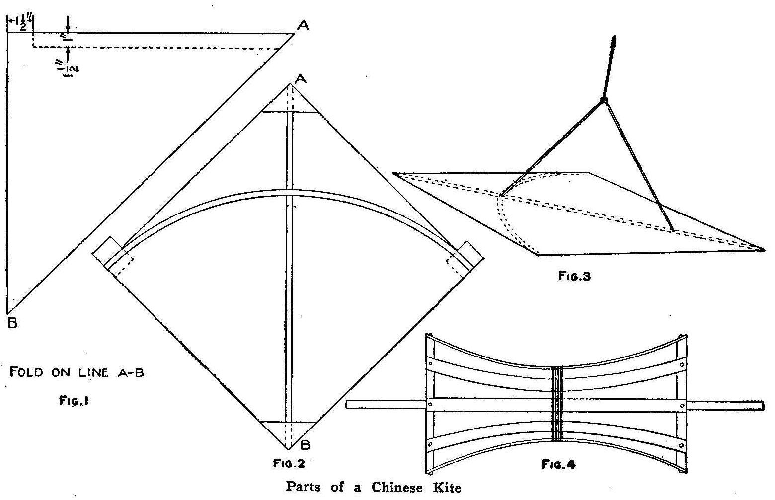
Parts of a Chinese Kite
The Chinese boy is not satisfied with simply holding the end of a
kite string and running up and down the block or field trying to
raise a heavy paper kite with a half pound of rags for a tail. He
makes a kite as light as possible without any tail which has the
peculiar property of being able to move in every direction.
Sometimes an expert can make one of these kites travel across the
wind for several hundred feet; in fact, I have seen boys a full
block apart bring their kites together and engage in a combat
until one of their kites floated away with a broken string, or
was punctured by the swift dives of the other, and sent to earth,
a wreck.
The Chinese boy makes his kite as follows:
From a sheet of thin but tough tissue paper about 20 in. square,
which he folds and cuts along the dotted line, as shown in Fig.
1, he gets a perfectly square kite having all the properties of a
good flyer, light and strong. He shapes two pieces of bamboo, one
for the backbone and one for the bow. The backbone is flat, 1/4
by 3/32 in. and 18 in. long. This he smears along one side with
common boiled rice. Boiled rice is one of the best adhesives for
use on paper that can be obtained and the Chinese have used it
for centuries while we are just waking up to the fact that it
makes fine photo paste. Having placed the backbone in position,
paste two triangular pieces of paper over the ends of the stick
to prevent tearing. The bow is now bent, and the lugs extending
from the sides of the square paper are bent over the ends of the
bow and pasted down. If the rice is quite dry or mealy it can be
smeared on and will dry almost immediately, therefore no strings
are needed to hold the bow bent while the paste dries.
After the sticks are in position the kite will appear as shown in
Fig. 2. The dotted lines show the lugs bent over the ends of the
bow and pasted down. Figure 3 shows how the band is put on and
how the kite is balanced. This is the most important part and
cannot be explained very well. This must be done by experimenting
and it is enough to say that the kite must balance perfectly. The
string is fastened by a slip-knot to the band and moved back and
forth until the kite flies properly, then it is securely
fastened.
A reel is next made. Two ends—the bottoms of two small peach
baskets will do—are fastened to a dowel stick or broom handle,
if nothing better is at hand. These ends are placed about 14 in.
apart and strips nailed between them as shown in Fig. 4, and the
centers drawn in and bound with a string. The kite string used is
generally a heavy packing thread. This is run through a thin
flour or rice paste until it is thoroughly coated, then it is run
through a quantity of crushed glass. The glass should be beaten
up fine and run through a fine sieve to make it about the same as
No.2 emery. The particles should be extremely sharp and full of
splinters. These particles adhere to the pasted string and when
dry are so sharp that it cannot be handled without scratching
the fingers, therefore the kite is flown entirely from the reel.
To wind the string upon the reel, all that is necessary is to lay
one end of the reel stick in the bend of the left arm and twirl
the other end between the fingers of the right hand.
A Chinese boy will be flying a gaily colored little kite from the
roof of a house (if it be in one of the large cities where they
have flat-roofed houses) and a second boy will appear on the roof
of another house perhaps 200 ft. away. Both have large reels full
of string, often several hundred yards of it. The first hundred
feet or so is glass-covered string, the balance, common packing
thread, or glass-covered string. As soon as the second boy has
his kite aloft, he begins maneuvering to drive it across the wind
and over to the first kite. First, he pays out a large amount of
string, then as the kite wobbles to one side with its nose
pointing toward the first kite, he tightens his line and
commences a steady quick pull. If properly done his kite crosses
over to the other and above it. The string is now payed out until
the second kite is hanging over the first one’s line. The wind
now tends to take the second kite back to its parallel and in so
doing makes a turn about the first kite’s string. If the second
kite is close enough, the first tries to spear him by swift
dives. The second boy in the meantime is see-sawing his string
and presently the first kite’s string is cut and it drifts away.
It is not considered sport to haul the other fellow’s kite down
as might be done and therefore a very interesting battle is often
witnessed when the experts clash their kites.
Contributed by S. C. Bunker, Brooklyn, N. Y.
Home-Made Vise
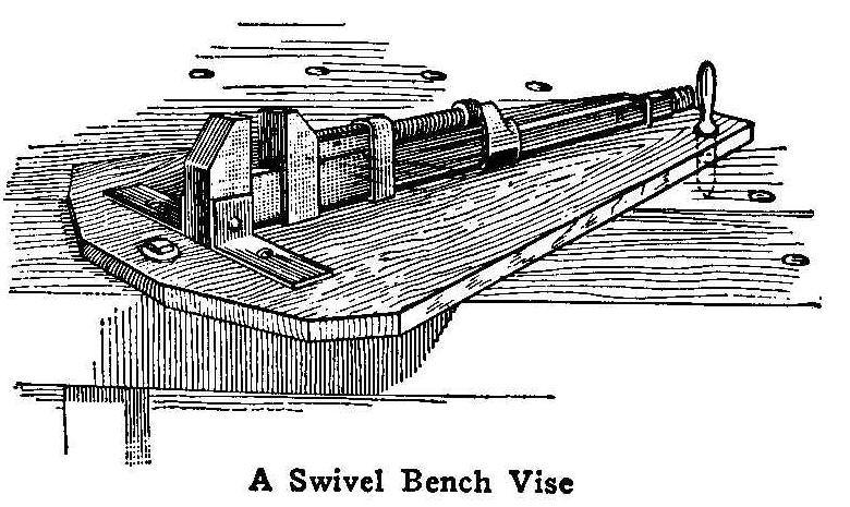
A Swivel Bench Vise
An ordinary monkey wrench that has been discarded is used in
making this vise. The wrench is supported by two L-shaped pieces
of iron fastened with a rivet through the end jaw, and these in
turn are bolted or screwed to the bench. The handle end is held
down with a staple. The inside jaw is used in clamping and is
operated with the thumb screw of the wrench. Two holes bored
through the thumb piece will greatly facilitate setting up the
jaws tightly by using a small rod in the holes as a lever.
The vise may be made into a swing vise if the wrench is mounted
on a board which is swung on a bolt at one end and held with a
pin at the other as shown in the illustration. Various holes
bored in the bench on an arc will permit the board to be set at
any angle.
Contributed’ by Harry S. Moody, Newburyport. Mass.
Home-Made Changing Bag for Plate Holders
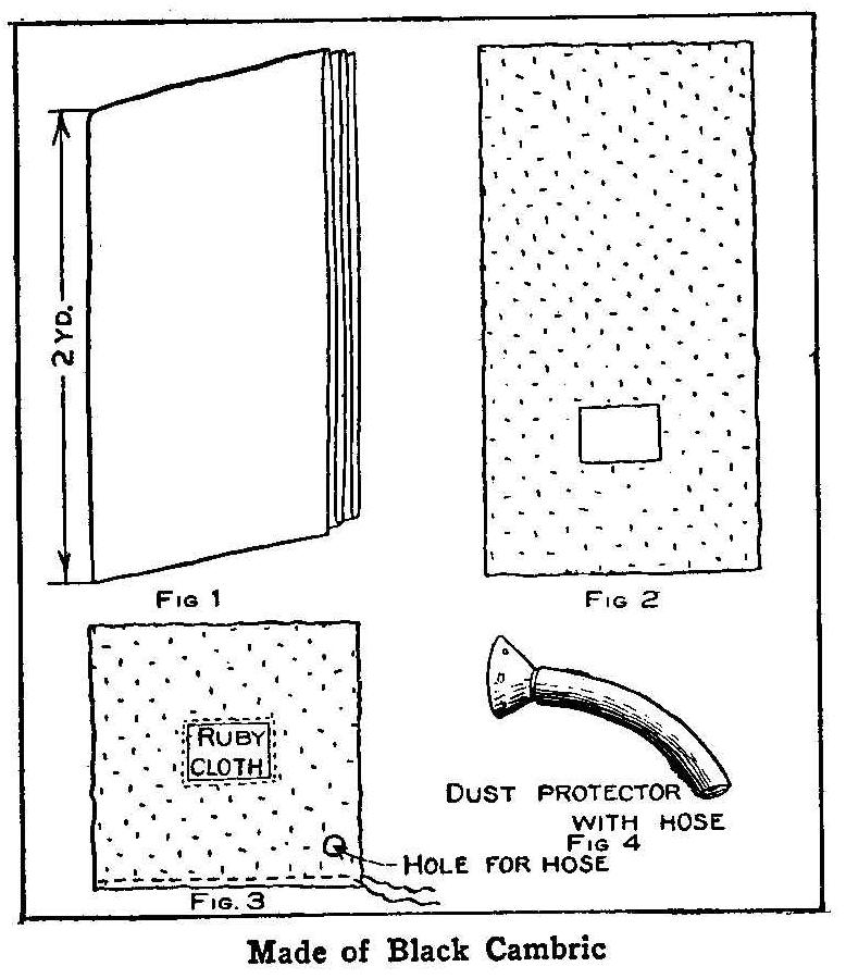
Made of Black Cambric
A good bag for changing plates and loading plate holders and one
that the operator can see well to work in can be made by anyone
on a sewing machine. Ten yards of black cambric or other black
cloth and a little ruby fabric will be required. Take the cambric
and fold it into 2-yd. lengths (Fig. 1) which will make five
layers of cloth, tack or fasten the layers together so they will
not slip and cut an 8-in. square hole in the middle of one half
(Fig. 2) and sew the ruby fabric over the opening. Be sure and
make the seam light-tight and have enough layers of ruby fabric
so no white light can get in. Fold the cloth up so it will be 1
yd. square (Fig. 3) and sew up the edges to make a bag with one
side open. Put a drawstring in the edge of the cloth around the
open side and the bag is complete ready for use.
Take the holders and plate boxes in the lap and put the bag over
the head and down around the body, then draw the string up tight.
A bag made up in this manner is for use only for a short time. If
it is necessary to do considerable work at a time, then a dust
protector, such as mill men use, must be attached to a 3-ft.
length of 2-in. rubber hose and the hose run through a hole in
the bag. This will make it possible to work in the bag as long as
you wish.
Contributed by Earl R. Hastings, Corinth, Vt.
Home-Made Asbestos Table Pads
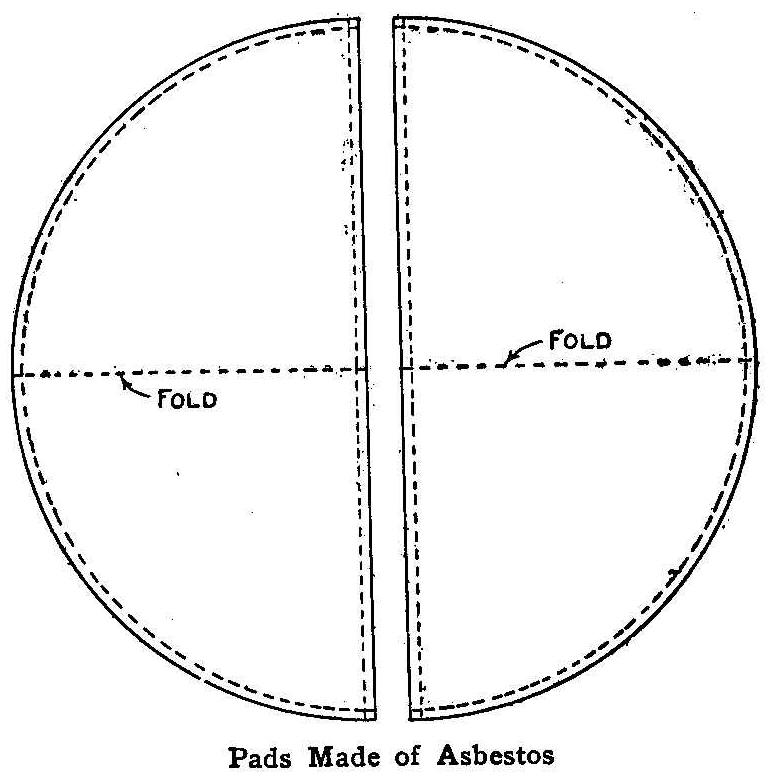
Pads Made of Asbestos
Asbestos
table pads to prevent the marring of polished table tops
from heated dishes can be easily made at home much cheaper than
they can be bought. Procure a sheet of
asbestos from a plumbing
shop and cut it in the shape of the top of your table. If the
table is round, make the pad as shown in the illustration,
cutting the circular piece into quarters. Cut four pieces of
canton flannel, each the size of half the table top. Two of the
asbestos pieces are
used to make one-half of the pad. Place the
two pieces with their edges together so they will form half a
circle disk and cover both sides with a piece of the flannel and
pin them in place. A binding of white cotton tape is then basted
around the edges to hold all the pieces together until they are
stitched on a sewing machine. A line of machine stitching is made
all around the outside and through the middle between where the
edges of the asbestos
sheets join together. This will form a
hinge so the two quarters may be folded for putting away. Make
the other half circular disk in the same way. If leaves are
wanted in extending the table, any number of pads can be made to
cover them in the same manner with the hinge in the middle of
each pad. The flannel is used with the nap side out so it will
make the pad soft and noiseless. This kind of a pad furnishes
perfect protection to the table from any heat or moisture.
Contributed by H. E. Wharton, Oakland, Calif.
How to Make a Ladies’ Handbag
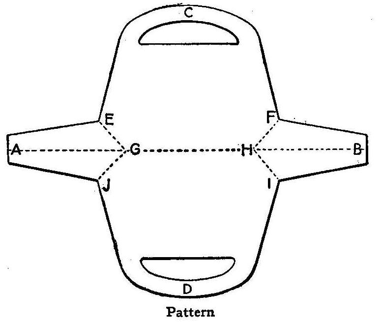
Pattern
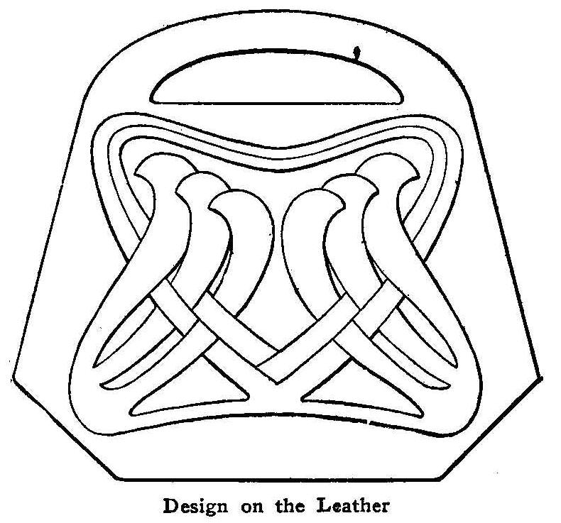
Design on the Leather
To make this bag, get a piece of Russian calf modeling leather. A
shade of brown is the best as it does not soil easily and does
not require coloring, which spoils the leather effect.
The dimensions of the full sized bag are: from A to B, 17-1/2 in.;
from C to D, 16-1/4 in.; from E to F, 9-1/4 in.; G to H, 6-1/4
in., and E to G, 2-1/4 in.
Enlarge the accompanying pattern to the given dimensions, trace
this or some other appropriate design on it, and then cut the
leather the size of the pattern.
Use a sponge to dampen the leather on the rough side, not so damp
that the water will come through to the right side when working,
but damp enough to allow the design to be well impressed on the
leather. Use a smooth, non-absorbent surface to lay the leather
on while at work.
Now lay the pattern on the right side of the leather and with the
smallest end of the leather tool or a sharp, hard pencil, trace
the design carefully on the leather. Moisten the leather as often
as necessary to keep it sufficiently moist to work well. Trace
the openings for the handles, also lines A-G, H-B, and E-G, G-J,
and corresponding lines on the other side.
Remove pattern and trace the design directly on leather with the
round point of tool, until it is made distinct and in marked
contrast to the rest of the leather. Do not make sharp marks but
round the edges of the lines nicely, with the rounded sides of
the tools.
To complete the bag, get something with which to make a lining. A
piece of oozed leather is the most satisfactory. Cut it the same
size as the bag, place both together and with a leather punch,
make holes all around the edge of the bag about 1/2 in. apart.
Cut out the leather for the handle openings. Care should be taken
not to cut the holes too near the edge of the bag lest the lacing
pull out. Now cut narrow thongs, about 1/8 in. wide, and lace
through the holes, lacing the sides of the end pieces in with the
sides of the bag. Crease the lines A-G and B-H inward for ends of
bag.
Removing Wire Insulation
The claw of a hammer can be used for removing the insulation on
copper wire, if not more than 1 in. is taken off at a time.
A Small Electric Motor
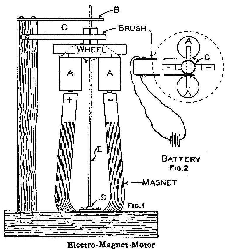
Electro-Magnet Motor
The drawing herewith shows a simple electric motor which can be
easily constructed by any boy who is at all handy with tools. I
made this motor many times when a boy and can say that if
carefully constructed it will run with greater rapidity than the
more expensive ones.
A common magnet which can be purchased at any toy store is used.
The one shown is 3-1/2 in. in length. The armature core is a
strip of 1/16 by 1/4-in. iron, 2-1/4 in. long, bent U-shaped and
fastened to the wood flywheel. Each leg of the armature is wound
with 10 ft. of No. 24 gauge magnet wire. The commutator is made
from an old 22 cartridge filed into two equal parts, each being a
half circle, both of which are made fast to a collar on the shaft
E. Each half of the commutator must be insulated from the other
half. The collar can be made by wrapping paper around the shaft
until the required size is obtained.
The top end of the shaft runs in a hole bored in a brass support,
B, which is screwed on the end of a piece of wood mortised in the
base, as shown in Fig. 1. The lower end of the shaft runs in a
glass bead, D, which is fastened to a small piece of brass with
sealing wax. The small brass piece is fastened to the base with
screws. The bead should not have an eye larger in diameter than
the shaft. The shaft is made from an old discarded knitting
needle. The brushes are fastened to each side of the upright
piece of wood supporting the brass bearing B.
The connections to the battery are shown in Fig. 2. Each half of
the commutator C is connected to the coils AA as shown in Fig. 1.
Contributed by J.M. Shannon, Pasadena, Calif.
Moving a Coin Under a Glass
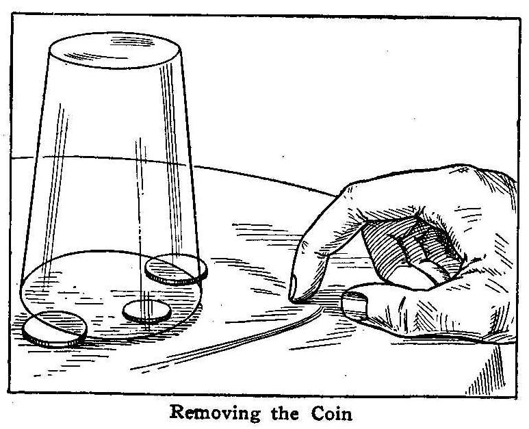
Removing the Coin
Place a penny or a dime on a tablecloth, towel or napkin and
cover it over with a glass in such a way that the glass will rest
upon two 25 or 50 cent pieces as shown in the sketch. The coin is
made to come forth without touching it or sliding a stick under
the edge of the glass. It is only necessary to claw the cloth
near the glass with the nail of the forefinger. The cloth will
produce a movement that will slide the coin to the edge and from
under the glass.
Improving Phonograph Sound
When playing loud and harsh records on a phonograph the music is
often spoiled by the vibration of the metal horn. This may be
remedied by buckling a valise or shawl strap around the horn,
near the center.
How to Make Paper Balloons
| Paper Balloon | Pattern and Parts to Make Balloon |
Balloons made spherical, or designed after the regular aeronaut’s
hot-air balloon, are the best kind to make. Those having an odd
or unusual shape will not make good ascensions, and in most cases
the paper will catch fire from the torch and burn before they
have flown very far. The following description is for making a
tissue-paper balloon about 6 ft. high.
The paper may be selected in several colors, and the gores cut
from these, pasted in alternately, will produce a pretty array
of colors when the balloon is in flight. The shape of a good
balloon is shown in Fig. 1. The gores for a 6-ft. balloon should
be about 8 ft. long or about one-third longer than the height of
the balloon. The widest part of each gore is 16 in. The widest
place should be 53-1/2 in. from the bottom end, or a little over
half way from the bottom to the top. The bottom of the gore is
one-third the width of the widest point. The dimensions and shape
of each gore are shown in Fig. 2.
The balloon is made up of 13 gores pasted together, using about
1/2-in. lap on the edges. Any good paste will do—one that is
made up of flour and water well cooked will serve the purpose. If
the gores have been put together right, the pointed ends will
close up the top entirely and the wider bottom ends will leave an
opening about 20 in. in diameter. A light wood hoop having the
same diameter as the opening is pasted to the bottom end of the
gores. Two cross wires are fastened to the hoop, as shown in Fig.
3. These are to hold the wick ball, Fig. 4, so it will hang as
shown in Fig. 5. The wick ball is made by winding wicking around
a wire, having the ends bent into hooks as shown.
The balloon is filled with hot air in a manner similar to that
used with the ordinary cloth balloon. A small trench or fireplace
is made of brick having a chimney over which the mouth of the
paper balloon is placed. Use fuel that will make heat with very
little smoke. Hold the balloon so it will not catch fire from the
flames coming out of the chimney. Have some alcohol ready to pour
on the wick ball, saturating it thoroughly. When the balloon is
well filled carry it away from the fireplace, attach the wick
ball to the cross wires and light it.
In starting the balloon on its flight, take care that it leaves
the ground as nearly upright as possible.
Contributed by R. E. Staunton.
A Simple Steamboat Model
Sectional View and Completed Boat
The small boat shown in the accompanying sketch may have a length
of 12 to 18 in. and is constructed in the following manner: A
small steam boiler, A, is supported by two braces over an alcohol
lamp in the middle of the boat. A small pipe is fastened to the
top of the boiler in such a way that the open end will be
opposite the open end of another pipe, B, somewhat larger in
size. The pipe B opens into the stern of the boat at C, as shown
in Fig. 1. The steam, coming through the small pipe A, is driven
forcibly through the larger pipe B, and carries with it a certain
amount of air out through the opening C into the water. As the
boat is driven forward by this force, the steam arises to the
surface in the form of bubbles. The boat soon attains
considerable speed, leaving a long wake behind.
To Remove Grease from Machinery
A good way to remove grease or oil from machinery before painting
is to brush slaked lime and water over the surface, leaving the
solution on over night. After washing, the iron is dried and the
paint will stick to it readily.
In removing grease from wood, common whitewash may be left on for
a few hours and then washed off with warm water, after which the
paint will adhere permanently.
A Game Played on the Ice
Bowling Over the Opponent’s Blocks
Two lines are drawn parallel on the ice from 50 to 100 ft. apart
and blocks of wood are placed every 6 ft. apart on these lines.
The player opening the game skates to the line and delivers, in
bowling form, a sliding block similar to the blocks that are
placed on the lines with the exception that it has a handle. The
blocks are about 6 in. wide by 6 in. high and 8 in. long. The
sliding blocks should be at least 1 ft. long and each provided
with a handle. The handle is attached by boring a hole near one
end in the middle of the block and driving in a wood pin. The
hole is bored slanting so as to incline the handle. Two of
these blocks are provided for the reason that when a player bowls
one of the opposing player’s blocks over the line he is entitled
to another throw. The side wins that bowls over all of the
opposing players’ blocks first. This will prove an interesting
and enjoyable pastime for skaters.
Making Photo Silhouette Brass Plaques
Fig. 1 Waxed Brass Plate
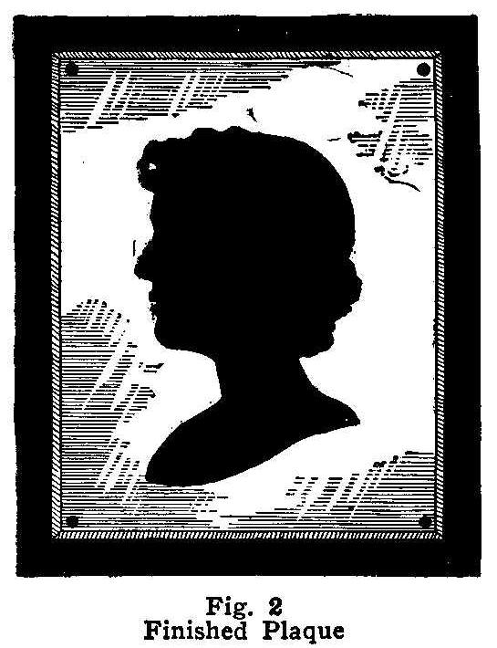
Fig. 2 Finished Plaque
Secure a brass plate having a smooth surface the right size for
the photograph and cover it with a coat of paraffin. This is done
by heating the paraffin in a vessel hot enough to make the wax
run freely, then pouring the liquid over the entire surface of
the brass.
When the paraffin has cooled sufficiently the outlines of the
photograph must be drawn upon its surface. There are three ways
of doing this: First, the photograph can be traced on tissue
paper and then retraced on the paraffin surface. The exact
outlines of the photograph can be obtained this way without
destroying the print. Second, if you have several copies of the
photograph, one can be utilized by tracing direct to the surface
of the paraffin. In using either of the two methods described,
carbon paper must be placed on the paraffin before the tissue
paper or photograph is laid upon it. Third, cut out the outlines
of the photograph and lay it on the paraffin surface, then trace
around the edges with the point of a needle or sharp point of a
knife. The outlines drawn by the first method are cut through the
paraffin in the same way. The paraffin is carefully removed from
the inside of the lines, leaving the brass surface perfectly
clean, as is shown in Fig. 1. The exposed part of the plate is
now ready to be etched or eaten away to the right depth with
acid. The acid solution is made up of 1-1/2 parts muriatic acid
and 2 parts water. The mixture should be placed in a glass or
earthenware vessel. If the plate is a small one a saucer will do
for the acid solution. Pour the acid on the plate where the
paraffin has been removed and allow it time to etch. The acid
should be removed every five minutes to examine the etching. If
any places show up where the paraffin has not been entirely
removed they must be cleaned so the acid will eat out the metal.
When the acid solution becomes weak new solution must be added
until the proper depth is secured. Rinse the plate in cold water,
stand in a tray and heat it sufficiently to run off all the
paraffin. Polish the plate by rubbing it with a piece of flannel.
The plaque can be given a real antique finish by painting the
etched part with a dull black paint. Drill a small hole in each
of the four corners, being careful not to dent the metal. The
plaque is backed with a piece of wood 3/4 in. thick, the
dimensions of which should exceed those of the brass plate
sufficiently to harmonize with the size of the plaque. The wood
should be painted black with the same paint used in the plaque.
Paint the heads of four thumb tacks black and use them in
fastening the plaque to the board. The finished silhouette will
appear as shown in Fig. 2.
Contributed by John A. Hellwig, Albany, N. Y.
Aligning Automobile Headlights
Automobile headlights should be set to throw the light straight
ahead, not pointed down at the road at an angle.
Telescope Stand and Holder
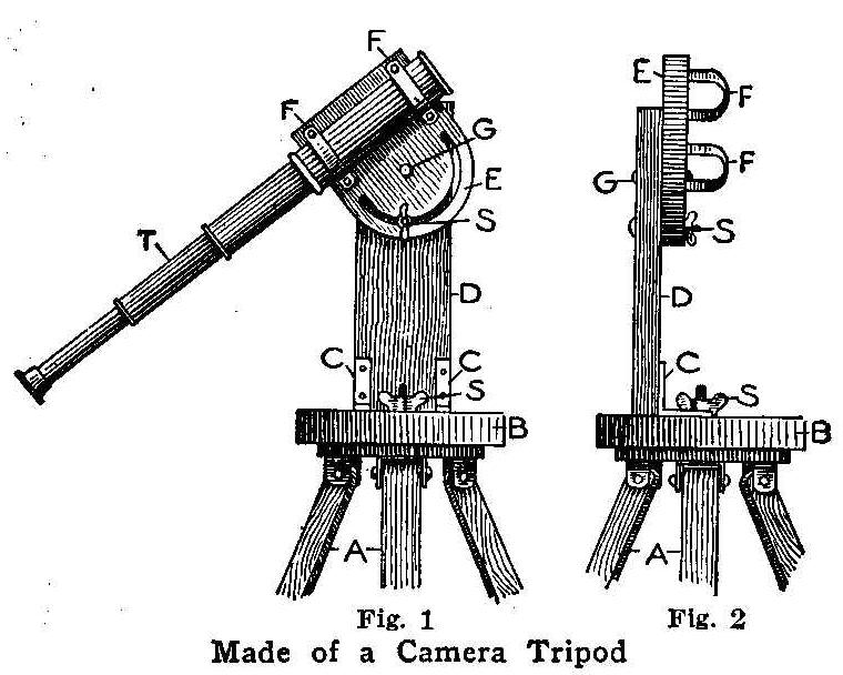
Fig. 1 Fig. 2
Made of a Camera Tripod
With the ordinary small telescope it is very difficult to keep
the line of sight fixed upon any particular object. To meet the
situation I constructed the device illustrated herewith. A
circular piece of wood, B, 6 in. in diameter, is fastened to a
common camera tripod, A, with a set screw, S. Corner irons, CC,
are screwed to the circular piece. These corner irons are also
screwed to, and supported in a vertical position by the wood
standard D, which is 4 in. wide and of any desired height. To
this standard is secured the wood shield-shaped piece E by the
screw G upon which it turns. A semi-circular slit is cut in the
piece G, through which passes the set screw S. The telescope is
secured to the piece G by means of the pipe straps FF. Rubber
bands are put around the telescope to prevent rubbing at the
places where the straps enclose it.
The wood pieces were made of 1/2 in. mahogany well rubbed with linseed
oil to give them a finish. The corner irons and set screws or
bolts with thumb-nuts can be purchased at any hardware store. The
pipe straps of different sizes can be obtained from a plumber’s
or gas and steam fitter’s store. With this device, either a
vertical or a horizontal motion may be secured, and, after
bringing the desired object into the line of sight, the set
screws will hold the telescope in position. Anyone owning a
tripod can construct this device in three or four hours’ time at
a trifling cost. In Fig. 1 is shown the side view of the holder
and stand, and Fig. 2 the front view.
It may be of interest to those owning telescopes without solar
eyepieces to know that such an eyepiece can be obtained very
cheaply by purchasing a pair of colored eyeglasses with very dark
lenses and metal rims. Break off the frame, leaving the metal
rims and nibs at each end. Place these over the eyepiece of the
telescope and secure in place with rubber bands looped over the
nibs and around the barrel of the instrument.
Contributed by R. A. Paine, Richmond, Va.
How to Make an Electrical Horn
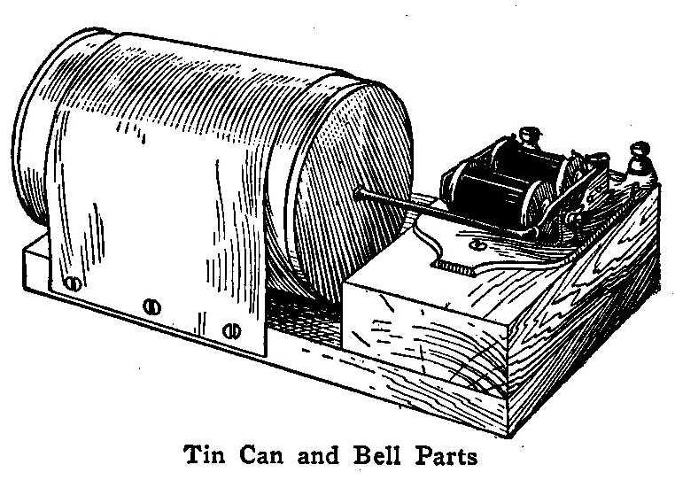
Tin Can and Bell Parts
Secure an empty syrup or fruit can, any kind having a smooth flat
bottom will do. If the bottom is not perfectly flat, it will
interfere with the regular tone vibrations, and not produce the
right sound. Remove the label by soaking it in hot water. Take an
ordinary electrical bell and remove the gong, clip off the
striking ball and bend the rod at right angles. Cut a block of
wood 3/4 in. thick, 5 in. wide and 8 in. long for the base.
Fasten the can on it with a piece of sheet brass or tin as shown
in the sketch. Mount the bell vibrator on the base, using a small
block of wood to elevate it to the level of the center of the
can, and solder the end of the vibrator rod to the metal.
Connect two dry cells to the bell vibrator, and adjust the
contact screw until a clear tone is obtained. The rapidly moving
armature of the bell vibrator causes the bottom of the can to
vibrate with it, thus producing sound waves. The pitch of the
tone depends on the thickness of the bottom of the can. This
horn, if carefully adjusted and using two cells of dry battery,
will give a soft pleasant tone that can be heard a block away. If
the two projecting parts of the vibrator are sawed off with a
hacksaw, it can be mounted on the inside of the can. This will
make a very compact electric horn, as only the can is
visible.
Contributed by John Sidelmier, La Salle, Ill.
Driving a Washing Machine with Motorcycle Power
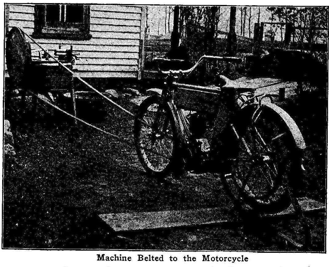
Machine Belted to the Motorcycle
The halftone illustration shows how I rigged up my washing
machine to be driven by the power from my motorcycle. I made a
wheel 26 in. in diameter of some 1-in. pine boards, shrunk an
iron band on it for a tire, and bolted it to the wheel on the
washing machine. A long belt the same width as the motorcycle
belt was used to drive the machine. The motorcycle was lined up
and the engine started, then the motorcycle belt thrown off and
the long belt run on, connecting the engine and washing machine
wheel.
I. R. Kidder, Lake Preston, S. D.
Home-Made Aquarium
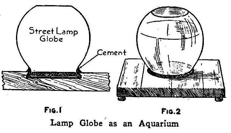
Lamp Globe as an Aquarium
A good aquarium can be made from a large-sized street lamp globe
and a yellow pine block. Usually a lamp globe costs less than an
aquarium globe of the same dimensions. Procure a yellow pine
block 3 in. thick and 12 in. square. The more uneven and twisted
the grain the better for the purpose, it is then less liable to
develop a continuous crack.
Cut out a depression for the base of the globe as shown in Fig.
1. Pour in aquarium cement and embed the globe in it. Pour more
cement inside of the globe until the cement is level with the top
of the block. Finish with a ring of cement around the outside and
sprinkle with fine sand while the cement is damp. Feet may be
added to the base if desired. The weight of the pine block makes
a very solid and substantial base for the globe and renders it
less liable to be upset.
Contributed by James R. Kane, Doylestown, Pa
Protect Your Lathe
Never allow lard oil to harden on a lathe.
Frame for Displaying Both Sides of Coins
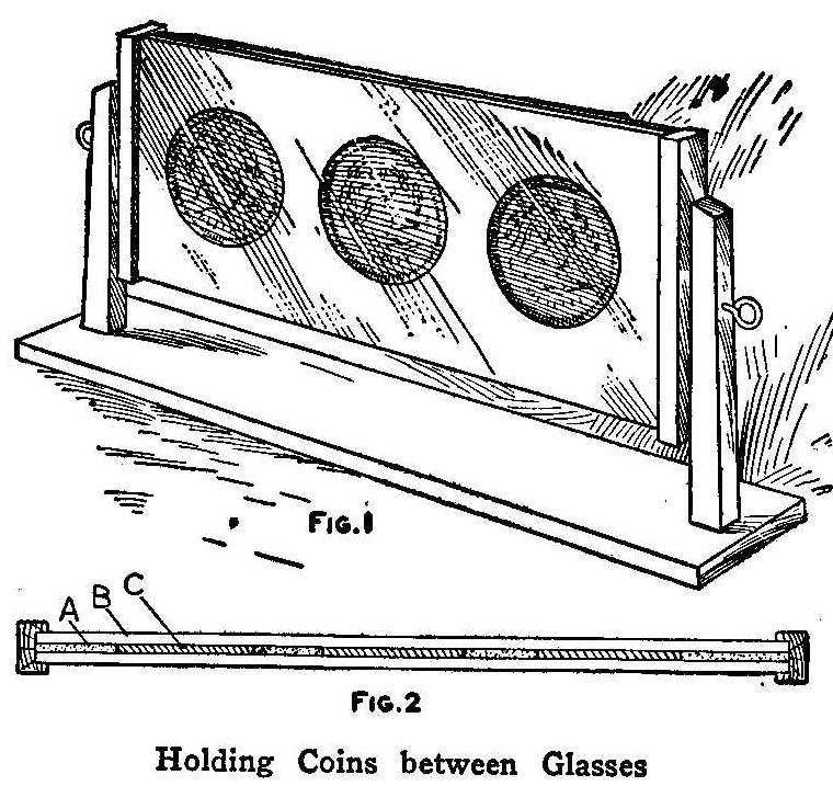
Holding Coins between Glasses
It is quite important for coin collectors to have some convenient
way to show both sides of coins without touching or handling
them. If the collection consists of only a few coins, they can be
arranged in a frame as shown in Fig. 1. The frame is made of a
heavy card, A, Fig. 2, the same thickness as the coins, and
covered over on each side with a piece of glass, B. Holes are cut
in the card to receive the coins C. The frame is placed on
bearings so it may be turned over to examine both sides. If there
is a large collection of coins, the frame can be made in the same
manner and used as drawers in a cabinet. The drawers can be taken
out and turned over.
Contributed by C. Purdy, Ghent, O.
How to Make Lantern Slides
A great many persons who have magic lanterns do not use them very
much, for after the slides have been shown a few times, they
become uninteresting, and buying new ones or even making them
from photographic negatives is expensive. But by the method
described in the following paragraph anyone can make new and
interesting slides in a few minutes’ time and at a very small
cost.
Secure a number of glass plates of the size that will fit your
lantern and clean them on both sides. Dissolve a piece of white
rosin in a half-pint of gasoline and flow it over one side of the
plates and allow to dry. Place the dried plate over a picture you
wish to reproduce and draw the outline upon the thin film. A lead
pencil, pen and ink or colored crayons can be used, as the rosin
and gasoline give a surface that can be written upon as easily as
upon paper. When the slide becomes uninteresting it can be
cleaned with a little clear gasoline and used again to make
another slide. A slide can be made in this way in five minutes
and an interesting outline picture in even less time than that.
This solution also makes an ideal retouching varnish for
negatives.
Contributed by J.E. Noble, Toronto, Canada.
How to Make a Developing Box
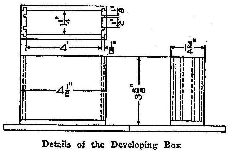
Details of the Developing Box
A box for developing 3-1/4 by 4-1/4 in. plates is shown in
detail in the accompanying sketch. It is made of strips of wood
1/4-in. thick, cut and grooved, and then glued together as
indicated. If desired, a heavier piece can be placed on the
bottom. Coat the inside of the box with paraffin or wax, melted
and applied with a brush. Allow it to fill all crevices so that
the developing box will be watertight. It will hold 4 oz. of
developer. Boxes for larger plates can be made in the same
manner. Use a small wooden clip in taking the plates out of the
box, being careful not to scratch the sensitive film.
Contributed by R.J. Smith, Milwaukee, Wis.
Staining Wood
A very good method of staining close-grained woods is to use
muriatic acid. The acid is put on with a brush like any ordinary
stain. The colors thus obtained are artistic and most beautiful,
and cannot be duplicated by any known pigment. The more coats
applied the darker the color will be. This method of staining has
the advantage of requiring no wiping or rubbing.
Contributed by August T. Neyer, One Cloud, Cal.
Sheet-Metal Whisk-Broom Holder
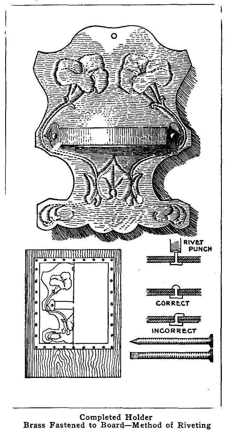
Completed Holder
Brass Fastened to Board-Method of Riveting
A whisk-broom holder such as is shown in the accompanying picture
may be easily made by the amateur. The tools needed are few: a
pair of tin shears, a metal block of some kind upon which to
pound when riveting, a hammer or mallet, several large nails, and
a stout board upon which to work up the design. A rivet punch is
desirable, though not absolutely necessary.
The material required is a sheet of No. 24 gauge copper or brass
of a size equal to that of the proposed holder, plus a 3/8-in.
border all around, into which to place the screws that are to be
used to hold the metal to the board while pounding it. The design
shown in the picture is 6 by 8 in. at the widest part and has
proven a satisfactory holder for a small broom.
Carefully work out the design desired on a piece of drawing
paper, both outline and decoration, avoiding sharp curves in the
outline because they are hard to follow with the shears when
cutting the metal. If the design is to be of two-part symmetry,
like the one shown, draw one part, then fold on a center line and
duplicate this by inserting double-surfaced carbon paper and
tracing the part already drawn. With this same carbon paper
transfer the design to the metal. Fasten the metal to the board
firmly, using 1/2-in. screws placed about 1 in. apart in holes
previously punched in the margin with a nail set or nail.
To flatten the metal preparatory to fastening it to the board,
place a block of wood upon it and pound on this block, never upon
the metal directly, or the surface will be dented and look bad in
the finished piece.
Take the nail, a 10 or 20-penny wire or cut, and file it to a
chisel edge, rounding it just enough to take the sharpness off so
that it will not cut the metal. This tool is used for indenting
the metal so as to bring out the outline of the design on the
surface.
There are several ways of working up the design. The simplest way
is to take the nail and merely “chase” the outlines of holder
design. Remove the screws, cut off the surplus metal and file the
edges until they are smooth. Make a paper pattern for the metal
band that is to hold the broom. Trace around this pattern on the
metal and cut out the shape. Punch rivet holes in holder and
band, also a hole by which to hang the whole upon the wall.
Rivet the band to the holder. Punch the rivet holes with a nail
set and make the holes considerably larger than the diameter of
the rivet, for in flattening the raised edges the holes will
close. Do the riveting on a metal block and keep the head of the
rivet on the back of the holder. Round up the “upset” end of the
riveted part as shown in the picture. Do not bend it over or
flatten it. This rounding is done by pounding around the outer
edge of the rivet end and not flat upon the top as in driving a
nail.
Clean the metal by scrubbing it off with a solution composed of
one-half water and one-half nitric acid.
Use a rag tied to a
stick and do not allow the acid to touch either your hands or
clothes. A metal lacquer may next be applied to keep the metal
from early corrosion.
How to Make a Camp Stool
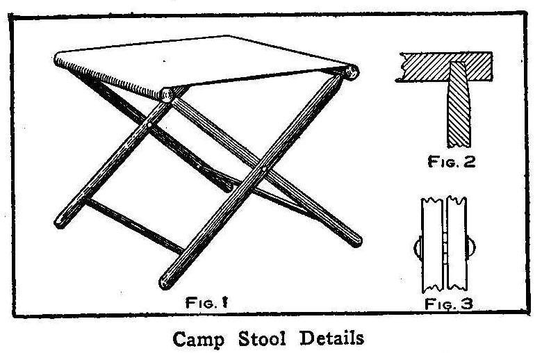
Camp Stool Details
The stool, as shown in Fig. 1, is made of beech or any suitable
wood with a canvas or carpet top. Provide four lengths for the
legs, each 1 in. square and 18-1/2 in. long; two lengths, l-1/8
in. square and 11 in. long, for the top, and two lengths, 3/4 in.
square, one 8-1/2 and the other 10-1/2 in. long, for the lower
rails.
The legs are shaped at the ends to fit into a 5/8-in. hole bored
in the top pieces as shown in Fig. 2, the distance between the
centers of the holes being 7-5/8 in. in one piece and 9-5/8 in.
in the other. The lower rails are fitted in the same way, using a
1/2-in. hole bored into each leg 2-1/2 in. up from the lower
end.
Each pair of legs has a joint for folding and this joint is made
by boring a hole in the middle of each leg, inserting a bolt and
riveting it over washers with a washer placed between the legs as
shown in Fig. 3. The entire length of each part is rounded off
for the sake of neatness as well as lightness.
About 1/2 yd. of 11-in. wide material will be required for the
seat and each end of this is nailed securely on the under side of
the top pieces. The woodwork may be stained and varnished or
plain varnished and the cloth may be made to have a pleasing
effect by stencilling in some neat pattern.
A Small Home-Made Electric Motor
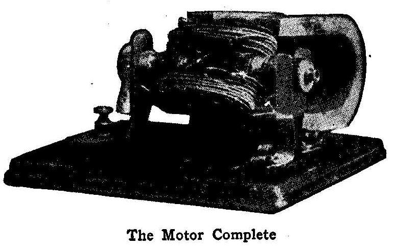
The Motor Complete
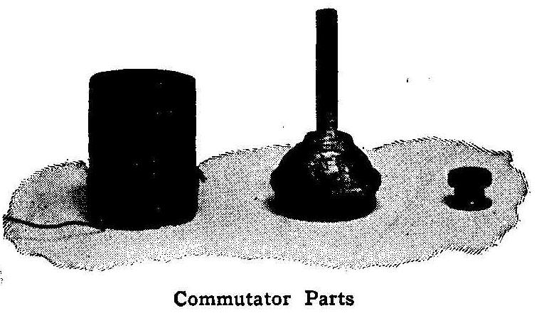
Commutator Parts
The accompanying photographs show the construction of a very
unique electric motor, the parts consisting of the frame from an
old bicycle pedal wrapped with insulated wire to make the
armature and three permanent magnets taken from an old telephone
magneto. The pedal, being ball bearing, rotated with very little
friction and at a surprisingly high rate of speed. The dust cap
on the end of the pedal was removed and a battery connection,
having quite a length of threads, was soldered to it as shown in
the photograph. The flanges were removed from an ordinary spool
and two strips of brass fastened on its circumference for the
commutator. The spool was held in position by a small binding
post nut. The shape of this nut made a good pulley for a cord
belt.
Contributed by John Shahan, Attalla, Ala.
Rocker Blocks on Coaster Sleds
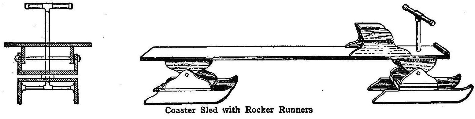
Coaster Sled with Rocker Runners
The accompanying sketch shows a coasting sled with rocker blocks
attached on both front and rear runners. The runners and the
other parts of the sled are made in the usual way, but instead of
fastening the rear runners solid to the top board and the front
runners to turn on a solid plane fifth wheel, they are pivoted so
each pair of runners will rock when going over bumps.
The illustration will explain this construction without going
into detail and giving dimensions for a certain size, as these
rocker blocks can be attached to any coaster or toboggan sled. It
will be noticed that the top board may bend as much as it will
under the load without causing the front ends of the rear runners
and the rear ends of the front runners gouging into the snow or
ice.
Contributed by W. F. Quackenbush, New York City.
How to Make a Watch Fob
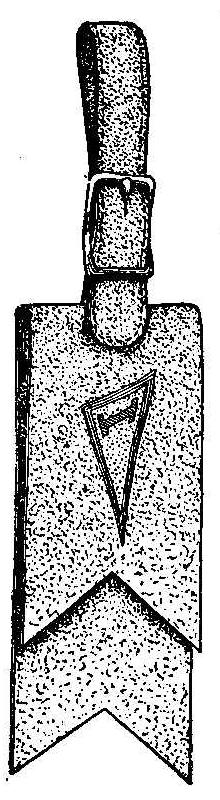
This novelty watch fob is made from felt, using class, college or
lodge colors combined in the making with emblems or initials
colored on the texture. Two pieces of felt, each 1-1/4 in. wide
and 4-1/4 in. long, are cut V-shaped on one end of each piece
about 1 in. in depth, and 3/8 in. in from the other end of one
piece cut a slit 1/2 in. long; the end of the other piece is
folded over, making a lap of about 1 in., and a slit is cut
through the double thickness to match the one cut in the first
piece. The desired emblem, initial, or pennant is stenciled on
the outside of the folded piece with class, college or lodge
colors. The strap is made from a strip of felt 3/16 in. wide and
8-1/4 in. long; stitched on both edges for appearance. Make a
hole with a punch 1-1/4 in. from one end, and two holes in the
other, one about 1 in. and the other 2-3/4 in. from the end.
Purchase a 1/2-in. buckle from a harness maker and you will have
all the parts necessary for the fob. Assemble as shown in the
sketch. The end of the strap having the two holes is put through
the slots cut in the wide pieces and the tongue of the buckle is
run through both holes. The other end is passed through the ring
of the watch and fastened in the buckle as in an ordinary belt.
Contributed by C. D. Luther. Ironwood. Mich.
Drill Lubricant
A good lubricant for drilling is made by dissolving 3/4 to 1 lb.
of sal-soda in one pailful of water.
New Way to Remove a Bottle Stopper
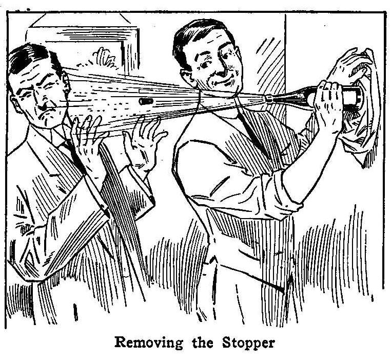
Removing the Stopper
Take a bottle of liquid, something that is carbonated, and with
the aid of a napkin form a pad which is applied to the lower end
of the bottle. Strike hard with repeated blows against the solid
surface of a wall, as shown in the sketch, and the cork will be
driven out, sometimes with so much force that a part of the
liquid comes with it and deluges the spectators, if desired by
the operator.
Imitation Fancy Wings on Hinges
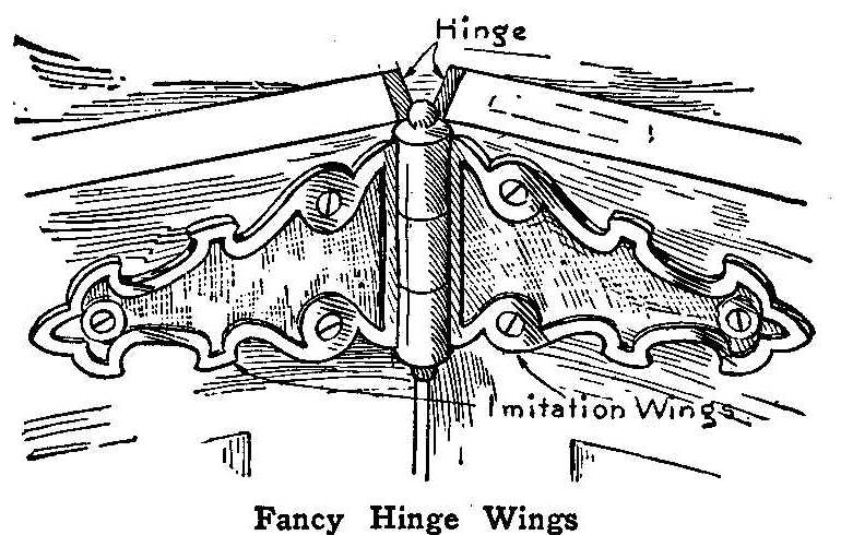
Fancy Hinge Wings
The accompanying sketch shows how I overcame the hardware
troubles when I was not able to find ready-made hinges in antique
design for a mission sideboard and buffet. This method allows a
wide range of designs, which can be made at home with ordinary
tools. The wings are made of copper or brass and finished in
repoussé, or can be tarnished and the high places burnished with
000 sandpaper or steel wool, then lacquered with white shellac or
banana bronzing liquid.
Contributed by John H. Schatz, Indianapolis, Ind.
How to Make a Child’s Rolling Toy
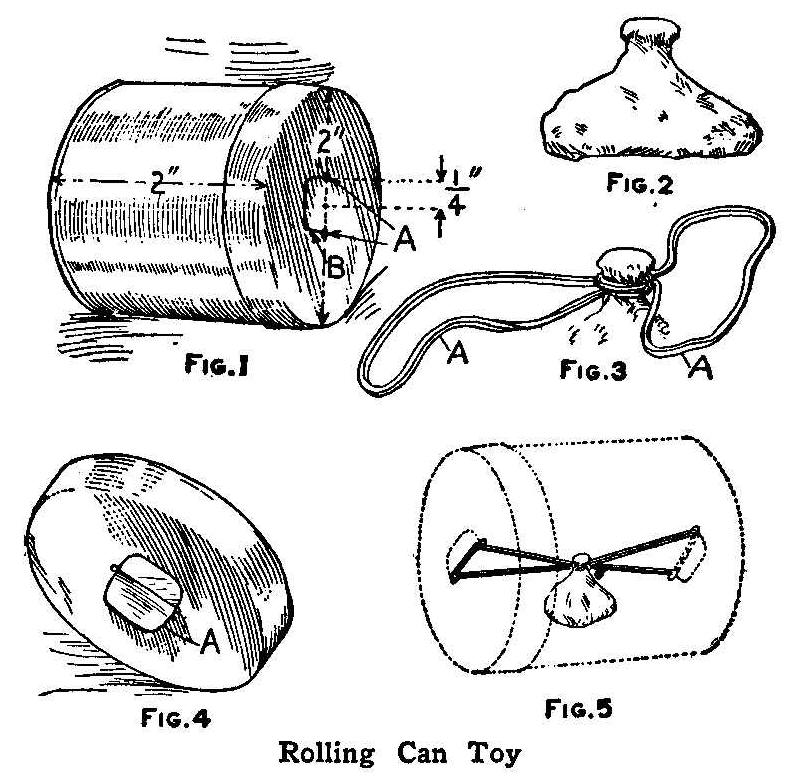
Rolling Can Toy
Secure a tin can, or a pasteboard box, about 2 in. in diameter
and 2 in. or more in height. Punch two holes A, Fig. 1, in the
cover and the bottom, 1/4 in. from the center and opposite each
other. Then cut a curved line from one hole to the other, as
shown at B. A piece of lead,
which can be procured from a
plumber, is cut in the shape shown in Fig. 2, the size being 1 by
1-1/8 by 1-1/4 in. An ordinary rubber band is secured around the
neck of the piece of lead,
as shown in Fig. 3, allowing the two
ends to be free. The pieces of tin between the holes A, Fig. 1,
on both top and bottom, are turned up as in Fig. 4, and the ends
of the bands looped over them. The flaps are then turned down on
the band and the can parts put together as in Fig. 5. The can may
be decorated with brilliant colored stripes, made of paper strips
pasted on the tin. When the can is rolled away from you, it winds
up the rubber band, thus storing the propelling power which makes
it return.
Contributed by Mack Wilson, Columbus, O.
How to Make a Portfolio
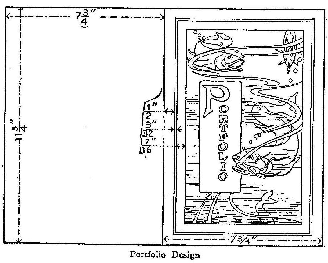
Portfolio Design
Secure a piece of Russian modeling calf leather of a size equal
to 12 by 16 in. Make a paper pattern of the size indicated in the
accompanying drawing, putting in the design.
The necessary tools consist of a stick with a straight edge and a
tool with an end shaped like that of a nutpick. A nutpick with a
V-shaped point will do if the sharpness is smoothed off by means
of a piece of emery paper, so that it will indent without cutting
the leather. These tools can be bought for this special purpose,
but are not essential for this piece if the nutpick is at hand.
There will also be needed a level, non-absorbent surface upon
which to lay the leather while working it. A piece of thick
glass, metal, or marble will serve.
Begin work by moistening the leather on the back side with a
sponge or cloth. Moisten as much as you dare and still not have
the moisture show on the face side. Next place the leather on the
glass, face up, and, holding the pattern firmly in place so that
it will not slip—if possible get some one to hold the pattern
for you—place the straight edge on the straight lines and mark
out or indent. After this has been done, mark over the design. A
pencil may be used the first time over. The pattern is now to be
removed and all the lines gone over with the tool to make them
deep and uniform.
The surplus stock around the edges may not be cut off. A neat way
to finish the edges is to punch a series of holes entirely around
through which a thin leather thong may be laced. If it is desired
to “line” the inside, this should be done before the holes are
punched or the lacing done.
Gear for Model Work
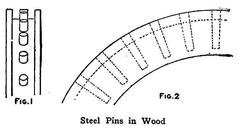
Steel Pins in Wood
When a gear is needed to drive a small pinion and there is none
of the right size at hand, one can be made in the following
manner: Turn up a wood disk to the proper diameter and 1/4 in.
thicker than the pinion, and cut a flat bottom groove 3/16 in.
deep in its face. The edges should be about 1/8 in. or more thick
on each side. Measure the distance between centers of two
adjacent teeth in the pinion and step this off around the
periphery in the bottom of the groove. Drill holes into the wood
on each point stepped off and insert steel pins made of wire,
allowing the end of each to protrude just far enough to act as a
tooth. In this way a good gear for light work can be quickly and
cheaply constructed.
Contributed by Henry Schaefer, New York City.
A Home-Made Vise
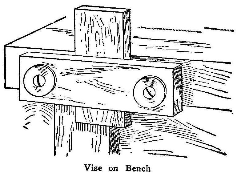
Vise on Bench
While making a box I had some dovetailing to do, and as there was
no vise on the bench I rigged up a substitute. I secured a board
3/4 in. thick, 3 in. wide and 20 in. long and bored a 1/2-in.
hole through it, 1 in. from each end. The board was then attached
to the bench with two screws passing through washers and the two
holes in the board into the bench top. The screws should be of
a length suitable to take in the piece to be worked.
Contributed by A. M. Rice, Syracuse, New York.
Cardboard Spiral Turned by Heat
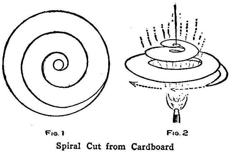
Spiral Cut from Cardboard
A novel attraction for a window display can be made from a piece
of stiff cardboard cut in a spiral as shown in Fig. 1. The
cardboard should be about 7 or 8 in. in diameter. Tie a piece of
string to the center point of the spiral and fasten it so as to
hang over a gas jet, Fig. 2. A small swivel must be put in the
string at the top or near the cardboard, if it is desired to have
the spiral run for any length of time. The cardboard will spin
around rapidly and present quite an attraction.
Contributed by Harry Szerlip, Brooklyn, N. Y.
A Workbench for the Amateur
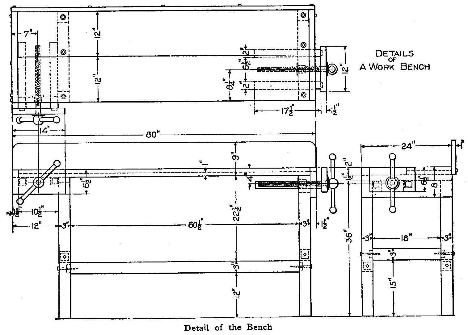
Detail of the Bench
The accompanying detail drawing shows a design of a portable
workbench suitable for the amateur woodworker. This bench can be
made easily by anyone who has a few sharp tools and a little
spare time. If the stock is purchased from the mill ready planed
and cut to length, much of the hard labor will be saved. Birch or
maple wood makes a very good bench, and the following pieces
should be ordered:
4 legs, 3 by 3 by 36.
2 side rails, 3 by 3 by 62-1/2 in.
2 end rails, 3 by 3 by 20 in.
1 back board, 1 by 9 by 80 in.
1 top board, 2 by 12 by 77 in.
1 top board, 1 by 12 by 77 in.
2 crosspieces, 1-1/2 by 3 by 24 in.
1 piece for clamp, 1-1/2 by 6-1/2 by 12 in.
1 piece for clamp, 1-1/2 by 6-1/2 by 14 in.
4 guides, 2 by 2 by 18 in.
1 screw block, 3 by 3 by 6 in.
1 piece, 1-1/2 by 4-1/2 by 10-1/2 in.
Make the lower frame first. Cut tenons on the rails and mortise
the posts, then fasten them securely together with 3/8 by 5-in.
lag screws as shown. Also fasten the 1-1/2 by 3 by 24-in. pieces
to the tops of the posts with screws. The heads should be
countersunk or else holes bored in the top boards to fit over
them. Fasten the front top board to the crosspieces by lag screws
through from the under side. The screws can be put in from the
top for the 1-in. thick top board.
Fasten the end pieces on with screws, countersinking the heads of
the vise end. Cut the 2-in. square holes in the 1-1/2 by 4-1/2 by
10-in. pieces for the vise slides, and fit it in place for the
side vise. Also cut square holes in the one end piece for the end
vise slides as shown. Now fit up the two clamps. Fasten the
slides to the front pieces with screws. Countersink the heads of
the screws so they will not be in the way of the hands when the
vise is used. The two clamp screws should be about 1-1/2 in. in
diameter. They can be purchased at a hardware store. A block
should be fitted under the crosspiece to hold the nut for the end
vise. After you have the slides fitted, put them in place and
bore the holes for the clamp screws.
The back board can now be fastened to the back with screws as
shown in the top view. The bench is now complete, except for a
couple of coats of oil which should be applied to give it a
finish and preserve the wood. The amateur workman, as well as the
pattern maker, will find this a very handy and serviceable bench
for his workshop.
As the amateur workman does not always know just what tools he
will need, a list is given which will answer for a general class
of work. This list can be added to as the workman becomes more
proficient in his line and has need for other tools. Only the
the better grade of tools should be
purchased as they are the cheapest in the
long run. If each tool is kept in a certain place, it can be
easily found when wanted.
1 bench plane or jointer;
1 jack plane or smoother;
1 cross cut saw, 24 in.;
1 rip saw, 24 in.;
1 claw hammer;
1 set gimlets;
1 brace and set of bits;
2 screwdrivers, 3 and 6 in.;
1 countersink;
1 compass saw;
1 set chisels;
1 wood scraper;
1 monkey wrench;
1 2-ft. rule;
1 marking gauge;
1 pair pliers;
1 nail set;
1 pair dividers;
1 pocket level;
1 6-in. try square;
1 oilstone;
No.1, 2 and 00 sandpaper.
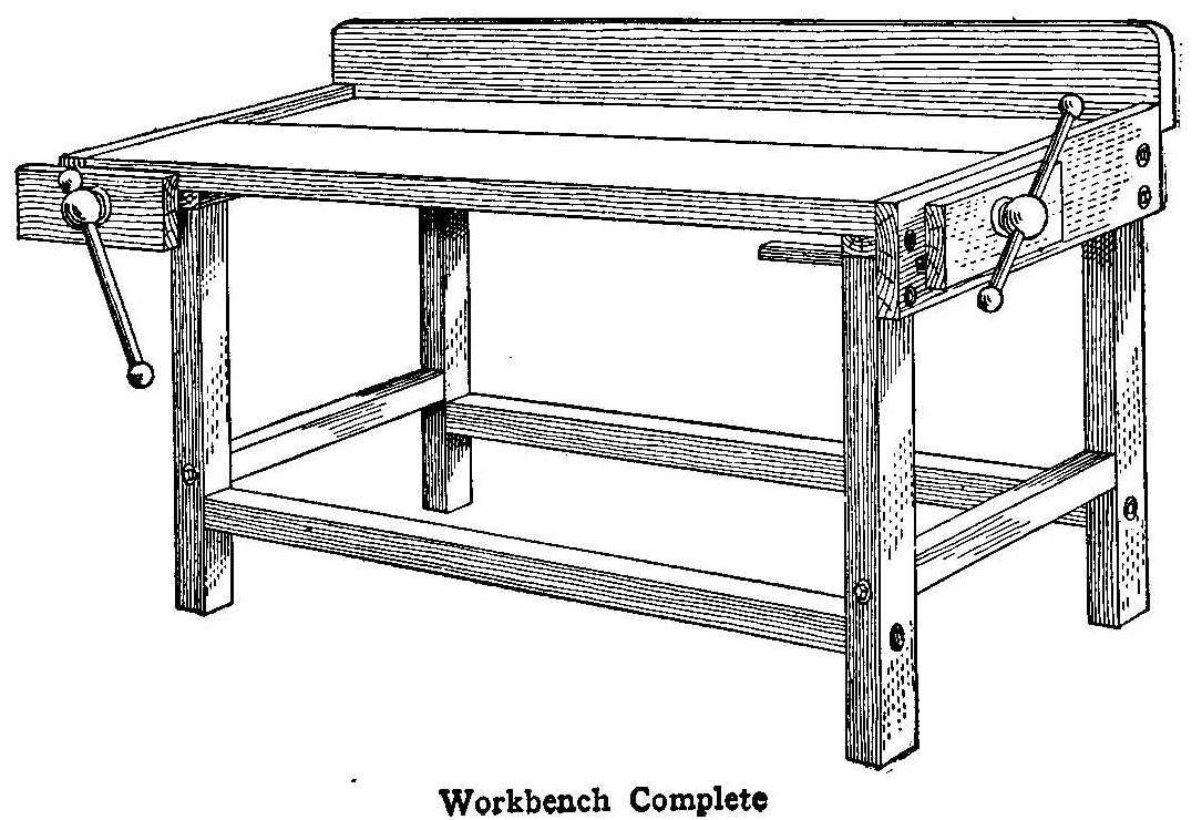
Workbench Complete
Repairing a Worn Knife Blade
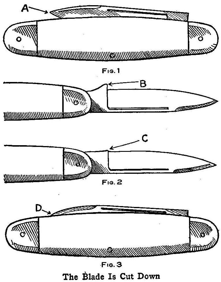
The Blade Is Cut Down
When the blade of a favorite pocket knife, after constant use,
becomes like A, Fig. 1, it is more dangerous than useful. To cut
down the already worn blade would leave only a stump, but if the
blade is fastened in a vise and the point B filed off until it is
like C, Fig. 2, the projecting point A, Fig. 1, will sink into
the handle as shown at D, Fig. 3, and the knife will be given a
new lease of usefulness.
Contributed by James M. Kane, Doylestown, Pa.
How to Make a Leather Spectacle Case
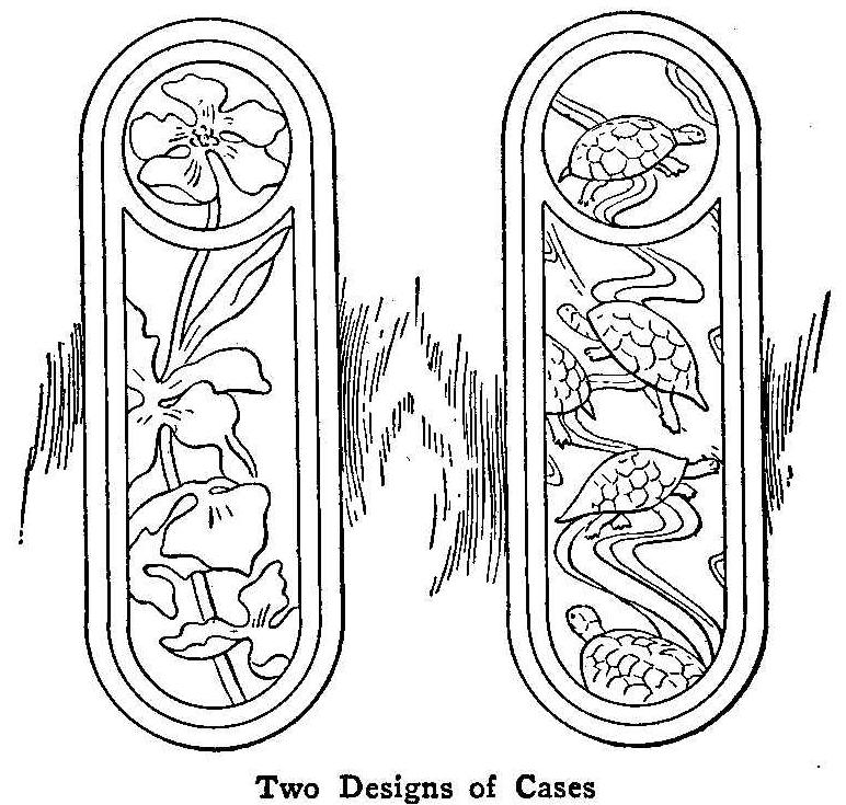
Two Designs of Cases
The spectacle case shown in the accompanying illustration may be
made of either calf or cow skin. The calf skin, being softer,
will be easier to work, but will not make as rigid a case as the
cow skin. If calf skin is to be used, secure a piece of modeling
calf. The extreme width of the case is 2-3/8 in. and the length
6-5/8 in. Two pieces will be required of this size. Put on the
design before the two parts are sewed together. First draw the
design on paper, then prepare the leather. Place the leather on a
small non-absorbent surface, such as copper or brass, and moisten
the back side with as much water as it will take and still not
show on the face side. Turn the leather, lay the design on the
face, and hold it in place while both the outline and decoration
are traced on the surface with a pencil or some tool that will
make a sharp line without tearing the paper.
After the outlines are traced, go over the indentations a second
time so as to make them sharp and distinct. There are special
modeling tools that can be purchased for this purpose, but a
V-shaped nut pick, if smoothed with emery paper so that it will
not cut the leather, will do just as well.
Take a stippling tool—if no such tool is at hand, a cup-pointed
nail set will do—and stamp the background. It is intended that
the full design shall be placed on the back and the same design
placed on the front as far as the material will allow. Be careful
in stamping not to pound so hard as to cut the leather. A little
rubbing on the point with emery will take off the sharpness
always found on a new tool.
Having prepared the two sides, they may be placed together and
sewed around the edges.
If cow hide is preferred, the same method of treatment is used,
but a form will need to be made and placed inside the case while
the leather is drying to give it the right shape. The form can be
made of a stick of wood.
Waterproofing a Wall
The best way to make a tinted wall waterproof is to first use a
material composed of cement properly tinted and with no glue in
it—one that will not require a glue size on the wall. After this
coating of cement is applied directly to the plaster, cover it
completely with water enamel and, when dry, give the surface a
thorough coating of varnish. This will make a perfectly
impervious covering, which steam, water or heat will not affect.
Contributed by Julia A. White, New York City.
Polishing Flat Surfaces
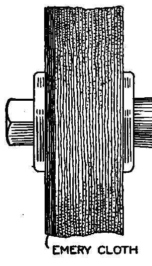
The work of finishing a number of brass castings with flat sides
was accomplished on an ordinary polishing wheel, from which the
first few layers of cloth were removed and replaced with emery
cloth. The emery surface of the cloth was placed outward and
trimmed to the same diameter as the wheel. This made a sanding
and polishing wheel in one.
Contributed by Chester L. Cobb, Portland, Maine.
Rubber Tip for Chair Legs
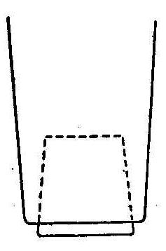
An inexpensive method of preventing a chair from scratching the
floor is to bore a hole of the proper size in the bottom end of
each chair leg and then procure four rubber stoppers of uniform
size and press them into place. This cushion of rubber eliminates
vibrations, and they will not slip nor mar the finest surface
upon which they rest.
Contributed by W. A. Jaquythe, Richmond, Cal.
Adjusting a Plumb-Bob Line
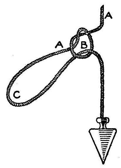
When plumbing a piece of work, if there is no help at hand to
hold the overhead line, it is common practice to fasten the plumb
line to a nail or other suitable projection. On coming down to
the lower floor it is often found that the bob has been secured
either too high or too low. When fastening the line give it
plenty of slack and when the lower floor is reached make a double
loop in the line, as shown in the sketch. Tightening up on the
parts AA will bind the loop bight B, and an adjustable
friction-held loop, C, will be had for adjusting the bob accurately
either up or down.
Contributed by Chas. Herrman, New York City.
Drier for Footwear
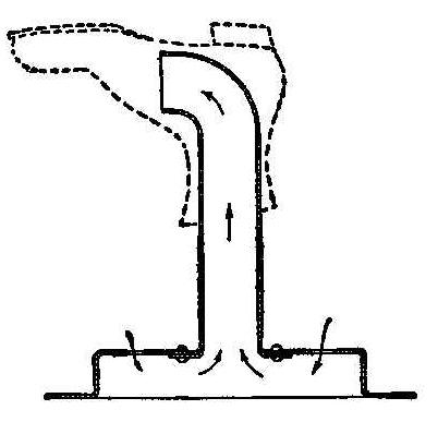
A drier for footwear can be readily made by a tinner, or anyone
that can shape tin and solder. The drier consists of a pipe of
sufficient length to enter the longest boot leg. Its top is bent
at right angles and the other end is riveted to a base, an
inverted stewpan, for instance, in whose bottom a few
perforations have been made to let air in. The boot or stocking
to be dried is placed over the pipe and the whole set on a heated
surface. The heat will cause a rapid circulation of air which
will dry the article quickly.
Contributed by Wm. Roberts, Cambridge, Mass.
Repairing A Roller Shade
A very satisfactory repair can be made by using a good
photographic paste to fasten a torn window shade to its roller.
A Shot Scoop
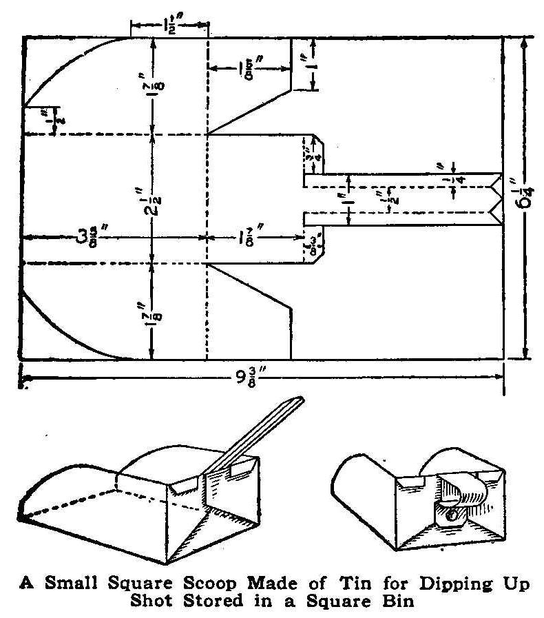
A Small Square Scoop Made of Tin for Dipping Up Shot Stored in a Square
Bin
In the ammunition department of our hardware store the shot was
kept in regular square bins and dished out with a round-bottom
scoop. This was very difficult, especially when the bottom of the
bin was nearly reached, as the round scoop would roll over them
and only pick up a few at a time. To overcome this difficulty I
constructed a square-shaped scoop that gave entire satisfaction.
The scoop can be used for other purposes as well.
A thick piece of tin, 6-1/4 by 9-3/4 in., was marked out as
shown, the pattern being cut on the full lines and bent on the
dotted ones. The strip for the handle was riveted to the end of
the scoop.
Contributed by Geo. B. Wright, Middletown, Conn.
Removing Grease Stains from the Leaves of a Book
Happening to get a grease spot on a page of a valuable book, I
found a way to remove it without injury to the paper, which has
been tried out several times with success. Heat an iron and hold
it as near as possible to the stain without discoloring the
paper, and the grease will disappear. If any traces of the grease
are left, apply powdered calcined magnesia. Bone, well calcined
and powdered, and plaster of Paris are also excellent absorbents
of grease.
A beautifully bound book, and quite new, had oil from a lamp
spilled over it. There was no quicklime to be had, so some bones
were quickly calcined, pulverized and applied. The next morning
there was no trace of oil, but only an odor which soon vanished.
Contributed by Paul Keller, Indianapolis, Ind.
Tightening Cane in Furniture
Split cane, used as part of furniture, such as chair seats, often
becomes loose and the threads of cane pull out. This can be
prevented by sponging with hot water, or by applying steaming
cloths to the cane. This process also tightens the shreds of cane
and does not injure ordinary furniture. If the article is highly
polished, care should be taken to prevent the hot water from
coming in contact with anything but the cane.
Cleaner for a Stovepipe
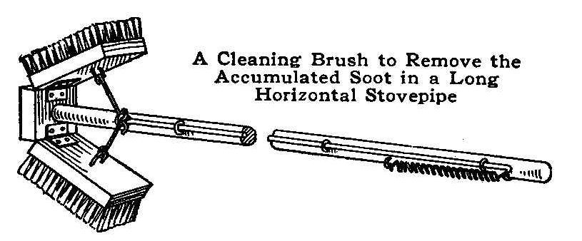
A long horizontal pipe for a stove soon fills with soot and must
be cleaned. The usual method is to beat the pipe after taking it
down to be cleaned, but a much better device for the purpose is
shown in the sketch.
A scrub brush is procured and cut in two, the parts being hinged
to a crosspiece fastened to a long broom handle. The brushes are
pressed outward against the inside surfaces of the pipe with a
wire and spring, as shown.
Contributed by C. L. Herbert, Chicago, Illinois.
Mounting Photo Prints on Glass
Photograph prints can be mounted on glass with an adhesive made
by soaking 1 oz. of sheet gelatine in cold water to saturation,
then dissolving in 3-1/2 oz. of boiling water. Let the solution
cool to about 110 deg. F., then immerse the print in it and
squeegee, face down, on a clear piece of glass. When dry, take a
damp cloth or soft sponge and wipe off any surplus gelatine on
the glass.
Dropping Coins in a Glass Full of Water
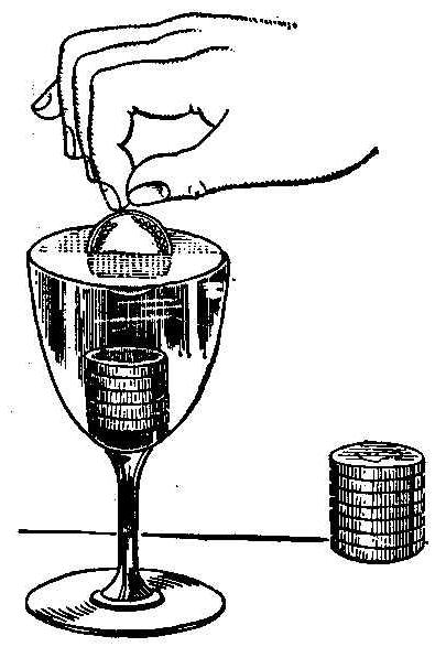
Take a glass and fill it to the brim with water, taking care that
the surface of the water is raised a little above the edge of the
glass, but not running over. Place a number of nickels or dimes
on the table near the glass and ask your spectators how many
coins can be put into the water without making it overflow. No
doubt the reply will be that the water will run over before two
coins are dropped in. But it is possible to put in ten or twelve
of them. With a great deal of care the coins may be made to fall
without disturbing the water, the surface of which will become
more and more convex before the water overflows.
Hollow-Grinding Ice Skates
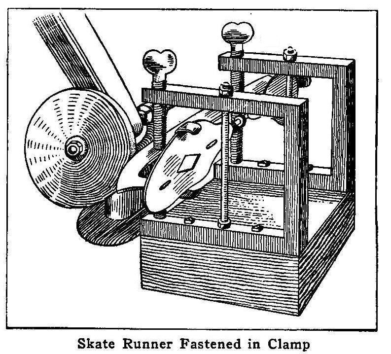
Skate Runner Fastened in Clamp
The accompanying sketch illustrates a practical method of
clamping ice skates to hold them for grinding the small arc of a
circle so much desired.
The U-shaped clamps are made of 3/4-in. soft steel with the
opening 6 in. deep and 5 in. high and are bolted to a block of
wood, 2 in. thick, 6 in. wide and 12 in. long. The skate runner
is adjusted to the proper height by 1/2-in.. set and thumbscrews.
The block of wood holding the clamp and skate can be pushed along
on the emery-wheel table in front of the revolving wheel.
If properly adjusted, a slight concave or hollow can be made full
length of the runner, true and uniform which will hold on the ice
sideways and not retard the forward movement.
Contributed by Geo. A. Howe, Tarrytown, New York.
How to Make a Bicycle Coasting Sled
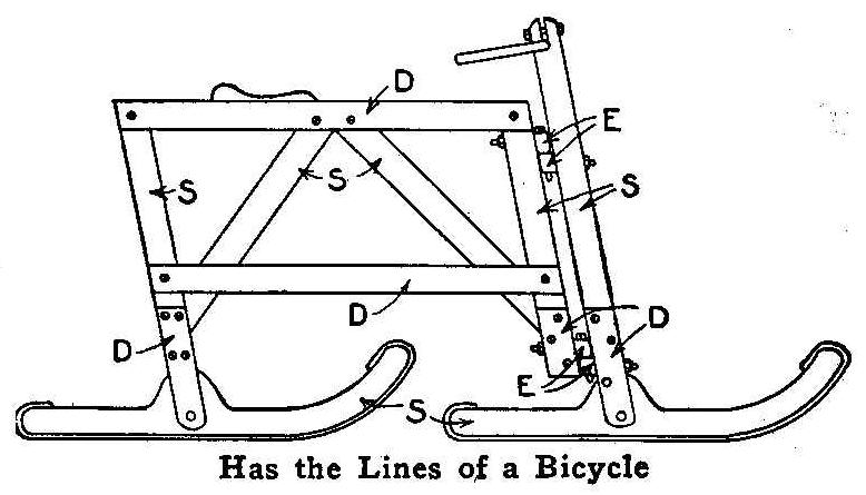
Has the Lines of a Bicycle
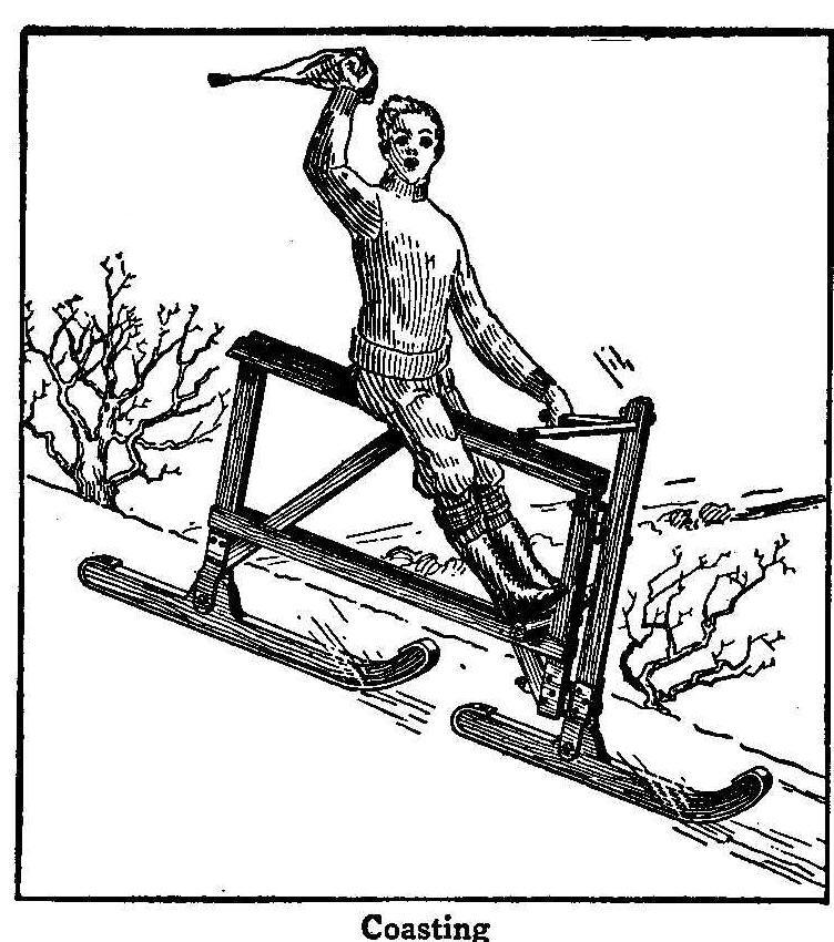
Coasting
The accompanying drawing and sketch illustrate a new type of
coasting sled built on the bicycle principle. This coaster is
simple and easy to make, says Scientific American. It is
constructed of a good quality of pine. The pieces marked S are
single, and should be about 1 by 1-1/2 in.; the pieces marked D
are double or in duplicate, and should be 1/2 by 1-1/2 in. The
runners are shod with iron and are pivoted to the uprights as
shown, double pieces being secured to the uprights to make a
fork. The seat is a board, to the underside of which is a block,
which drops down between the two top slats and is secured with a
pin. A footrest is provided consisting of a short crosspiece
secured to the front of the frame and resting on the two lower
slats. The frame and front fork are hinged together with four
short eyebolts, E, with a short bolt through each pair as shown.
Spelling Names with Photo Letters
Letters Made from photographs
There are, no doubt, many amateur photographers who make only
occasional trips afield or through the more traveled
thoroughfares with their cameras during the winter months. Each
one is generally interested in working up the negatives that he
or she made during the summer or on that last vacation into
souvenir post cards, albums and the like, for sending to friends.
Illustrated herewith is something different from the album or
photographic calendar. The letters forming part of the word
POPULAR are good examples of this work.
The masks which outline the letters are cut from the black paper
in which plates come packed. Their size depends on the plate
used. A sharp knife, a smooth board and a straightedge are all
the tools needed, says Camera Craft. If the letters are all cut
the same height, they will look remarkably uniform, even if one
is not skilled in the work of forming them all in accordance with
the rules. Be sure to have the prints a little larger than the
letters to insure a sufficient margin in trimming, so as to have
a white margin around the finished letters. The best method is to
use a good pair of scissors or a sharp knife.
Many combinations can be made of these letter pictures to spell
out the recipient’s name or the season’s greeting. During the
holidays the letters may be made from winter scenes to spell “A
Merry Christmas” or “A Happy New Year.” An Easter greeting may
have more spring-like subjects and a birthday remembrance a
fitting month. The prints are no more difficult to make than the
ordinary kind. In cutting out an 0, for example, do not forget to
cut out a piece to correspond to the center. This piece can be
placed on the printing paper after the outline mask has been laid
down, using care to get it in the right position, and closing the
frame carefully so that the small piece will not be disturbed.
The letters should be of the kind to give as large an area of
surface to have as much of the picture show as possible. What the
printer calls black face letters are the most suitable.
By cutting the letters out of black paper in a solid form, and using
these as a mask for a second printing after printing the full
size of the negatives, these letter pictures can be made with a
black border. So made, they can be trimmed to a uniform black
line all around; and, mounted on a white card and photographed
down to post card size, the greeting so spelled out makes a most
unique souvenir. Another application of the letters in copying is
to paste them on a white card as before, trim the card even with
the bottoms of the letters, stand the strip of card on a mirror
laid flat on a table, and then photograph both the letters and
their reflections so as to nicely fill a post card. Still another
suggestion is to cut out the letters, after, pasting the prints
on some thin card, and then arrange them in the desired order to
spell out the name or greeting, but with flowers interspersed and
forming a background, photographing them down to the desired
size. A third means of securing a novel effect by photographing
down an arrangement of the letters is to have them cut out in
stiff form as in the last method; mount them on short pieces of
corks, in turn fastened to a white card forming the background.
So arranged, the letters will stand out from the card about 1/2
in. If they are now placed in a light falling from the side and
slightly in front, each letter will cast a shadow upon the
background, and in the finished print the letters will look as if
suspended in the air in front of the surface of the card.
Holding a Loose Screw
A piece of sheet lead put on each
side of a screw will fill up and hold the threads in a too large
hole.
A Checker Board Puzzle
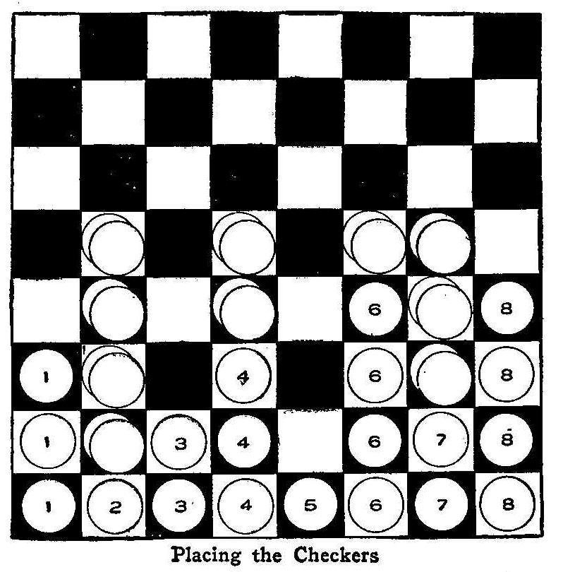
Placing the Checkers
Place eight checker men upon the checker board as shown in the
first row in the sketch. The puzzle is to get them in four piles
of two men each without omitting to jump over two checker men
every time a move is made.
The first move is to jump 5 over 4 and 3 on 2 which is shown in
the second row, then jump 3 over 4 and 6 on 7 and the positions
will appear as shown in the third row; jump 1 over 2 and 5 on 4
to get the men placed like the fourth row and the last move is to
jump 8 over 3 and 7 on 6 which will make the four piles of two
men each as shown in the fifth row.
Contributed by I. G. Bayley, Cape May Point, N.J.
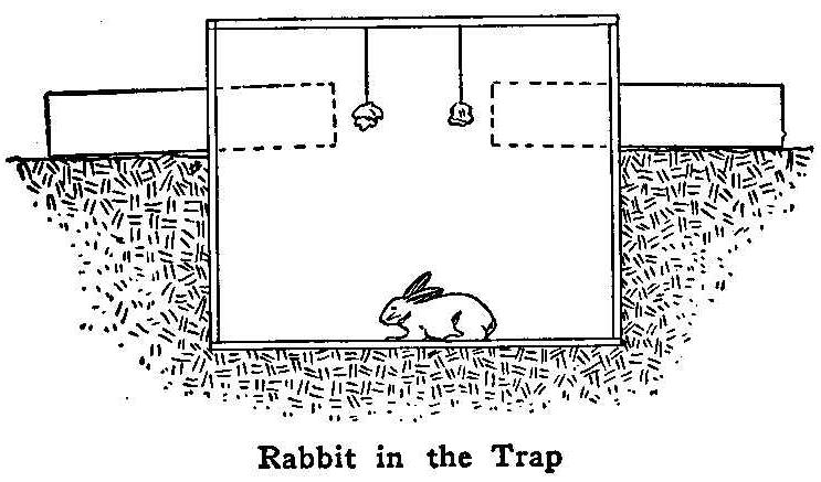
Rabbit in the Trap
A good serviceable rabbit trap can be made by sinking a common
dry goods box in the ground to within 6 in. of its top. A hole 6
or 7 in. square is cut in each end level with the earth’s surface
and boxes 18 in. long that will just fit are set in, hung on
pivots, with the longest end outside, so they will lie
horizontal. A rabbit may now look through the two tubes, says the
American Thresherman. The bait is hung on a string from the top
of the large box so that it may be seen and smelled from the
outside. The rabbit naturally goes into the holes and in this
trap there is nothing to awaken his suspicion. He smells the
bait, squeezes along past the center of the tube, when it tilts
down and the game is shot into the pit, the tube righting itself
at once for another catch. The top and sides of the large box may
be covered with leaves, snow or anything to hide it. A door
placed in the top will enable the trapper to take out the
animals. By placing a little hay or other food in the bottom of
the box the trap need not be visited oftener than once a week.
Old-Time Magic
Changing a Button into a Coin
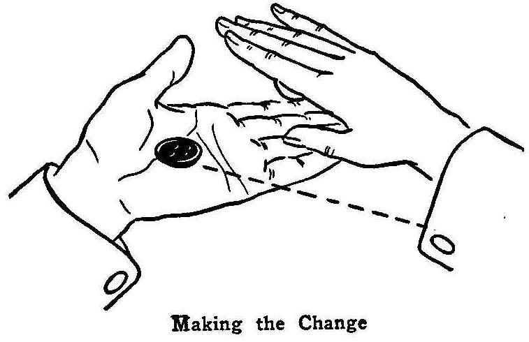
Making the Change
Place a button in the palm of the left hand, then place a coin
between the second and third fingers of the right hand. Keep the
right hand faced down and the left hand faced up, so as to
conceal the coin and expose the button. With a quick motion bring
the left hand under the right, stop quick and the button will go
up the right-hand coat sleeve. Press the hands together, allowing
the coin to drop into the left hand, then expose again, or rub
the hands a little before doing so, saying that you are rubbing a
button into a coin.
Contributed by L. E. Parker, Pocatello, Idaho.
Buttonhole Trick
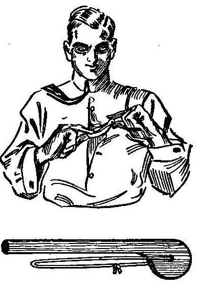
This trick is performed with a small stick having a loop attached
that is too small for the stick to pass through. Spread out the
string and place it each side of the buttonhole, then draw the
cloth around the hole through the string until it is far enough
to pass the stick through the hole. Pull back the cloth and you
have the string looped in the hole with a hitch the same as if
the stick had been passed through the string.
The stick may be removed by pulling up the loop as if you were
passing the stick through it, putting the stick in the hole and
leaving the string on the outside, then spread the string,
pulling up the cloth and passing the stick through the hole as
before.
Contributed by Charles Graham, Pawtucket, Rhode Island.
How to Remove Paper from Stamps
Old stamps as they are purchased usually have a part of the
envelope from which they are taken sticking to them and in
removing this paper many valuable stamps are torn or ruined.
Place all the stamps that are stuck to pieces of envelopes in hot
water and in a short time they can be separated without injury.
Dry the stamps between two white blotters. Stamps removed in this
way will have a much better appearance when placed in an album.
Contributed by L. Szerlip, Brooklyn, N. Y.
Imitation Arms and Armor
Part I
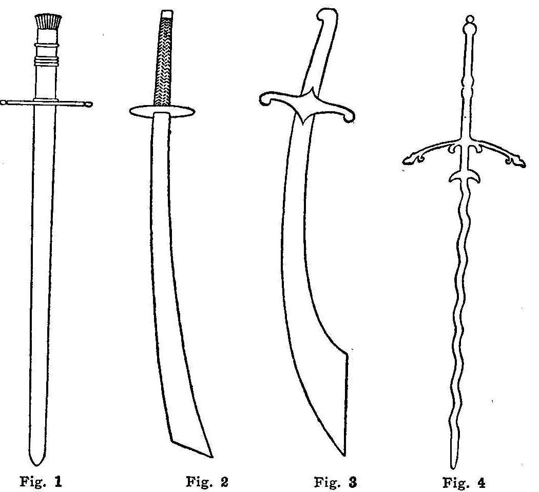
Fig.1 Fig.2 Fig.3 Fig.4
Genuine antique swords and armor, as used by the knights and
soldiers in the days of old, are very expensive and at the
present time practically impossible to obtain. The accompanying
illustration shows four designs of swords that anyone can make,
and if carefully made, they will look very much like the genuine
article.
The drawings are so plain that the amateur armorer should have
very little difficulty, if any, in building up his work from
the illustrations, whether he requires a single sword only, or a
complete suit of armor, full size.
The pieces or designs in this article are from authentic
sources, says the English Mechanic, so that where names are given
the amateur can so label them, and will thereby greatly add to
their interest and value.
An executioners’ sword of the fifteenth century is shown in Fig.
1. The blade should be about 27 in. long with a handle of
sufficient length to be grasped by both hands. The width of the
blade near the handle is about 2-1/2 in., tapering down to 1-1/2
in. near the point end. Several ridges are cut around the handle
to permit a firm grip. The cross guard is flat and about 1 in. in
width.
Mark out the shape and size of the blade on a piece of wood 1/8
in. thick, using a straightedge and a pencil, and allowing a few
inches more in length on which to fasten the handle. Cut out the
wood with a scroll saw or a keyhole saw, trim the edges down thin
and smooth both surfaces with fine sandpaper. The end for the
handle is cut about 1 in. wide and 2 in. long. The cross guard is
cut out and a hole made in the center through which to pass the
handle end of the blade. The handle is next made, and if the
amateur does not possess a lathe on which to turn the shape of
the handle, the ridges around the wood may be imitated by gluing
and tacking on pieces of small rope. The handle is then mortised
to receive the 1 by 2-in. end of the blade. The cross guard is
now glued and placed on the blade, then the hole in the handle is
well glued with glue that is not too thick and quite hot. The
blade with the cross guard is inserted in the handle and allowed
to set. When the glue is thoroughly dry, remove the surplus with
a sharp knife and paint the handle with brown, dark red, or green
oil paint. The blade is covered with tinfoil to give it the
appearance of steel. Secure some pieces of tinfoil and cut one
strip 1/2 in. wider than the blade and the other 1/4 in.
narrower. Quickly paint the blade well with thin glue on one
side., then lay evenly and press on the narrow strip of tinfoil.
Glue the other side of the blade, put on the wider strip of
tinfoil and glue the overlapping edge and press it around and on
the surface of the narrow strip. The cross guard must be covered
with tinfoil in the same manner as the blade. When the whole is
quite dry, wipe the blade with light strokes up and down several
times, using a soft and dry piece of cloth. The sword is then
ready to hang in its chosen place as a decoration, not for use
only in cases of tableaux, for which this article will be
especially useful to those who are arranging living pictures
wherein swords and armor are part of the paraphernalia.
A Chinese scimitar is shown in Fig. 2. The handle of this sword
is oval and covered with plaited cord. In making this scimitar,
follow the directions as for Fig. 1, except that the handle has
to be covered with a round black cord. If it is found difficult
to plait the cord on the handle as in the illustration, wind it
around in a continuous line closely together, and finish by
fastening with a little glue and a small tack driven through the
cord into the handle. The pommel is a circular piece of wood, 1/8
in. thick and 5 in. in diameter. The length of the handle,
allowing for a good hold with both hands, should be about 9 in.,
the length of the blade 28 in., the width near the pommel 1-1/2
in. and 3 in. in the widest part at the lower end. The sharp or
cutting edge is only on the short side, the other is flat or
half-round.
A Turkish sabre of ancient manufacture from Constantinople is
shown in Fig. 3. The handle is painted a dull creamy white in
imitation of ivory. The enamel paint sold in small tins will
answer well for this purpose. The cross guard and blade are
covered as described in Fig. 1. The sharp edge is on the longer
curved side, the other is flat or half-round.
A two-handed sword used in the 14th and 15th centuries is shown
in Fig. 4. This sword is about 68 in. long, has a cross guard and
blade of steel with a round wood handle painted black. The ball
or pommel on top of the handle is steel. Both edges of the blade
are sharp. This sword is made in wood the same as described for
Fig. 1.
A Dovetail Joint Puzzle

How the Joint Is Cut
A simple but very ingenious example in joinery is illustrated. In
the finished piece, Fig. 1, the dovetail appears on each side of
the square stick of wood, the illustration, of course, shows only
two sides, the other two are identical. The joint is separable
and each part is solid and of one piece. In making, take two
pieces of wood, preferably of contrasting colors, such as cherry
and walnut or mahogany and boxwood, about 1-1/2 in. square and of
any length desired. Cut the dovetail on one end of each stick as
shown in Fig. 2, drive together and then plane off the triangular
corners marked A. The end of each piece after the dovetails are
cut appear as shown in Fig. 3, the lines marking the path of the
dovetail through the stick.
Radiator Water
Pure rain water is the best to use in a cooling system of an
automobile engine, as it is free from the mineral substances
which are deposited in the radiator, piping and jackets by hard
water.
Springboard for Swimmers
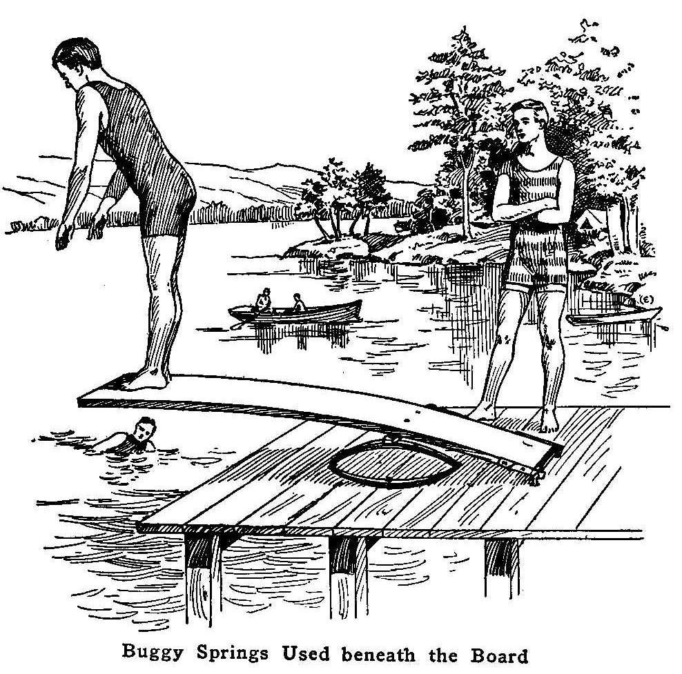
Buggy Springs Used beneath the Board
A good springboard adds much to the fun of swimming. The boards
are generally made so that the plank will bend, being dressed
down thin at one end and fastened. The thinness of the plank, or
an insecure fastening, causes many a plank to snap in two or come
loose from its fastenings in a short time.
The accompanying sketch shows the method of constructing a
springboard that does not depend upon the bending of the wood for
its spring. It is made of a plank, 2 in. thick and from 14 to 16
ft. long, one end of which is secured with a hinge arrangement
having a U-shaped rod whose ends are held with nuts. On each edge
of the board, at the lower end, are fastened two pieces of strap
iron, each about 1 ft. long and with the lower ends drilled to
fit the horizontal of the U-shaped rod.
Secure a pair of light buggy springs from a discarded rig and
attach them to the ends of a square bar of iron having a length
equal to the width of the plank. Fasten this to the plank with
bolts, as shown in the sketch. Should the springs be too high
they can be moved forward.
Contributed by John Blake, Franklin, Mass.
Taking Button from a Child’s Nostril
A three-year-old child snuffed a button up its nostril and the
mother, in an attempt to remove it, had caused the button to be
pushed farther up the channel. Doctors probed for the button
without success. The distracted mother happened to think of
snuff, and, as there was some at hand, took a pinch of snuff
between the thumb and forefinger and held it close to the child’s
nose. The violent sneezing caused the button to be blown out.
Such an accident may come under the observation of any parent,
and if so, this method can be used to relieve the child when
medical assistance is not at hand.
Contributed by Katharine D. Morse, Syracuse, N. Y.
Brass Frame in Repoussé
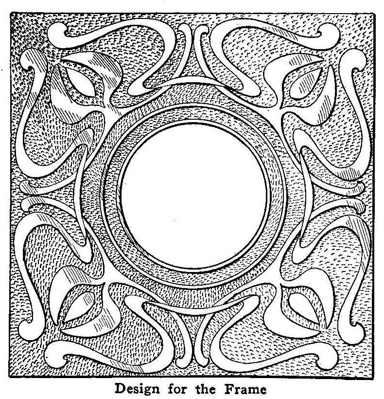
Design for the Frame
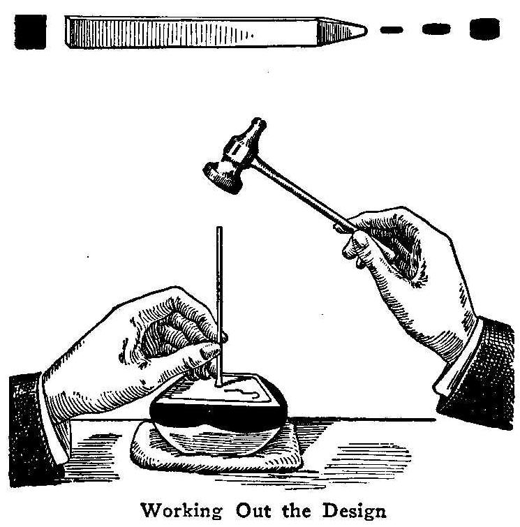
Working Out The Design
Punches can be purchased, as can the pitch bed or block. Both can
be made easily, however. Several punches of different sizes and
shapes will be needed. A piece of mild steel, about 3/8 in.
square, can be easily worked into tools shaped as desired. A cold
chisel will be needed to cut the metal to length; a file to
reduce the ends to shape, and a piece of emery paper to smooth
and polish the end of the tool so that it will not scar the
metal.
A small metal box must be secured to hold the pitch. The
illustration shows an iron receptacle. The pitch is prepared by
heating the following materials in these proportions: pitch, 5
lb.; plaster of Paris, 5 lb.; tallow, 1/2 lb. To put it in
another way, use pitch and plaster in equal parts with 1/10 part
tallow. See that the pitch and plaster are dry so that the
moisture will not cause the pitch to boil over. Keep stirring the
mass so that it never boils. Melt the pitch first and add the
plaster by degrees.
For a piece of repoussé such as the frame shown, secure a piece
of brass of about No. 18 gauge. With carbon paper trace the
design on the brass. Place the metal on the pitch bed and work
over the outline of the design. Use the chisel-edged tool and try
to make the lines continuous. When this has been done, heat the
pitch slightly and place the metal, design down, on the pitch,
and with the raising punches work up the shape as desired after
the pitch has hardened. When the desired form has been obtained,
turn the metal over and “touch up” any places improperly raised.
The metal will probably be warped somewhat. To remedy this, place
a board on the metal and pound until the metal assumes a flat
shape again. Next drill a hole in the center waste and saw out
for the opening, using a small metal saw. Trim up the edges and
file them smooth.
Clean the metal thoroughly, using powdered pumice with
lye.
Cotton batting fastened to the end of a stick will make a good
brush. Upon the cleansed metal put a lacquer to prevent
tarnishing. Metal clips may be soldered to the back to hold the
picture in place and also a metal strip to hold the frame
upright. These should be placed before the metal is lacquered.
Finding the Horsepower of Small Motors
A small motor often excites curiosity as to its true horsepower,
or fraction of a horsepower. Guesses in this direction vary
remarkably for the same motor or engine. It is comparatively easy
to determine the horsepower put out by almost any machine by the
following method which is intended for small battery motors and
small steam engines.
Before giving the description, it may be well to know what
horsepower means. Horsepower is the rate of work and a unit is
equal to 33,000 ft. lb. per minute, or 550 ft. lb. per second.
That is lifting 33,000 lb. 1 ft. in one minute or 550 lb. 1 ft.
in one second. This may be applied to the problem of finding the
horsepower of a motor by fastening a piece of twine about 25 ft.
long to the shaft of the engine or motor to be tested in such a
way that when the shaft revolves it will wind up the string
similar to a windlass. Place the motor in such a position that
the twine will hang freely without touching anything: out of a
high window will do. Fasten a weight to the other end of the line
as heavy as the motor or engine can lift and still run. It must
weigh enough to slow the power down a little, but not to stop it.
Mark the position of the weight and start the motor, at the same
time accurately measuring time in minutes and seconds it takes to
lift the weight from the lowest point to the highest. Next
measure accurately the distance in feet covered by the weight in
its ascent and obtain the correct weight in pounds of the weight.
Multiply the weight by the distance covered and divide the result
by the number of minutes or fraction of a minute obtained and
divide this last result by 33,000 and the quotient will be the
horsepower of the motor or engine.
Perhaps an illustration will make this solution much plainer.
Suppose the motor will lift a weight of 1 lb. and still revolve,
30 ft. in 10 seconds or 1/6 of a minute. Multiplying 1 by 30 we
get 30, which divided by 1/6 gives 180. This in turn divided by
33,000 equals in round numbers 1/200 part of a horsepower.
Contributed by Harold H. Cutter.
Illusion for Window Attraction
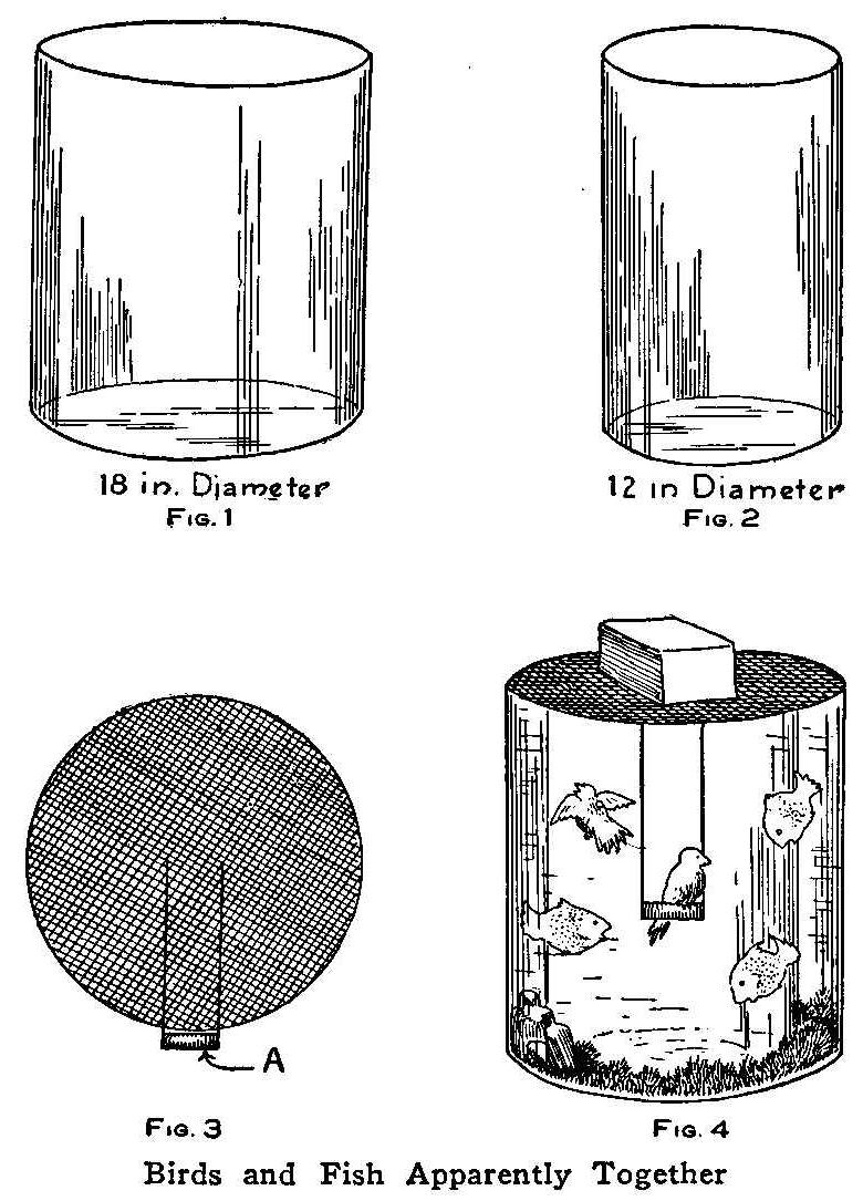
| 18 in. Diameter Fig. 1 | 12 in. Diameter Fig. 2 |
| Fig. 3 | Fig. 4 |
Birds and Fish Apparently Together
Gold fish and canary birds, living together in what seems like
one receptacle, make an unusual show window attraction. Secure
two glass vessels having straight sides of the same height, one
18 in. in diameter (Fig. 1) and the other 12 in. in diameter
(Fig. 2). The smaller is placed within the larger, the bottoms
being covered with moss and aquarium decorations which can be
purchased at a bird store. Fill the 3-in. space between the
vessels with water. Cut a piece of galvanized screen into
circular form to cover the larger vessel, and hang a bird swing,
A, Fig. 3, in the center. Place the screen on top of the vessels
so that the swing will hang in the center of the inner vessel. A
weight—a box filled with sand will do—should be placed on top
of the screen, over the smaller vessel, to keep it from floating.
Moss should be put over the top of the screen so that the two
separate vessels can not be seen. Place the birds in the inner
vessel and the fish in the water. The effect is surprising. To
complete the effect and aid the illusion the vessels can be set
in a box lined with black velvet, or on a pedestal.
Contributed by J. F. Campbell, Somerville, Mass.
Cleaner for White Shoes
Finely ground whiting mixed with water to the consistency of
paste makes a very good coating for white shoes. A brush can be
used in applying the mixture which will dry in a few minutes. It
is best to mix only as much paste as required for immediate use.
Contributed by L. Szerlip, Brooklyn, N. Y.
Crossing Belt Laces
Belt laces should never cross on the side next to the pulley as
they will cut themselves in two.
How to Make a Candlestick Holder
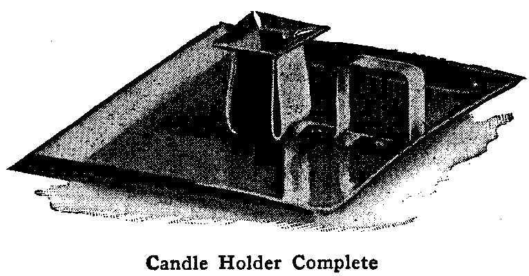
Candle Holder Complete
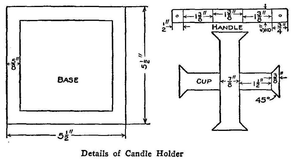
Details of Candle Holder
A candlestick of very simple construction and design can be made
as follows: Secure a piece of brass or copper of No. 23 gauge of
a size sufficient to make the pieces detailed in the accompanying
sketch. A riveting hammer and a pair of pliers will be needed,
also a pair of tin shears and a piece of metal upon which to
rivet. Cut out a piece of metal for the base to a size of 5-1/2
by 5-1/2 in. Trim the sharp corners off slightly. Draw a pencil
line all around the margin and 5/8 in. away from the edge. With
the pliers shape the sides as shown in the illustration.
Next lay out the holding cup according to the plan of development
shown, and cut out the shape with the shears. Polish both of
these pieces, using any of the common metal polishes. Rivet the
cup to the base, and then, with the pliers, shape the sides as
shown in the photograph. The manner of making and fastening the
handle is clearly illustrated. Use a file to smooth all the cut
edges so that they will not injure the hands.
In riveting, care should be taken to round up the heads of the
rivets nicely as a good mechanic would. Do not be content merely
to bend them over. This rounding is easily accomplished by
striking around the rivets’ outer circumference, keeping the
center high.
A good lacquer should be applied after the parts have been
properly cleaned and polished, to keep the metal from tarnishing.
A Home-Made Duplicator
The usual gelatine pad, which is the principal part of the
average hectograph or duplicator, is, as a rule, unsatisfactory,
as it is apt to sour and mold in the summer and freeze in the
winter, which, with other defects, often render it useless after
a few months service.
A compound that is almost indestructible is the preparation sold
at art stores as modeling clay. This clay is as easily worked as
a putty and is spread into the tray, which may be of wood or tin,
and the surface leveled by pounding with a mallet or hammer, then
by drawing a straightedge over it.
The surface of the pad is now saturated with pure glycerine. This
is poured upon the surface after it is slightly warmed, covering
the same and then laying a cloth over the pad and allowing it to
stand long enough for the clay to absorb the glycerine, after
which it is ready for use.
The original copy is written with a copying pencil or typewritten
through a hectograph ribbon. A sheet of newspaper is laid upon
the pad and a round stick or pencil is passed over it to make the
surface level and smooth. Remove the newspaper and place the
original copy face down on the leveled surface and smooth it out
in the same way so that every part touches the pad. Remove the
copy in about five minutes and place the clean sheets of paper
one after another on the surface and remove them. From 50 to 75
copies of the original can be made in a short time.
This compound is impervious to water, so the negative print is
removed by simply washing with a damp sponge, the same as
removing writing from a slate. This makes it possible to place
another original on the pad immediately without waiting for the
ink to vanish by chemical action as in the original hectograph.
The action of the weather has no effect upon this compound and it
is proof against accident, for the tray may be dropped and the
pad dented or cut into pieces, and the clay can be pressed back
and leveled. The only caution is to keep it covered with a cloth
saturated in glycerine while not in use.
Contributed by A. A. Houghton, Northville, Mich.
Paper-Clip Bookmark
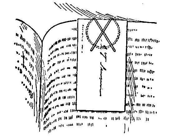
The combination of a paper clip and a calling card makes a good
bookmark. The clip and card can be kept together by piercing the
card and bending the ends of the wire to stick through the holes.
The clip is attached to a page as shown in the sketch.
Contributed by Thos. DeLoof, Grand Rapids, Mich.
Aerating Water in a Small Tank
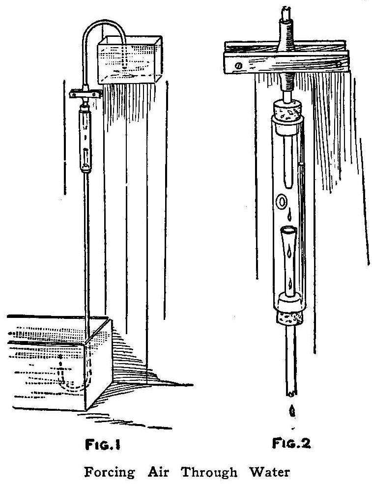
A simple way of producing air pressure sufficient to aerate water
is by the use of a siphon as shown in Fig. 1. The siphon is made
of glass tubes, the longer pieces being bent on one end as shown.
The air receiver and regulating device are attached to the top
end of the lower tube, as shown in Fig. 2. The receiver or air
inlet is the most important part. It is made of a glass tube, 3/4
in. in diameter and 5 in. long. A hole is filed or blown through
one side of the glass for the admission of air. The ends of the
smaller glass tubes are passed through corks having a diameter to
fit the ends of this larger tube. The ends of these tubes should
be so adjusted that the continuous drops of water from the upper
will fall into the tube below. The succession of air bubbles thus
imprisoned are driven down the tube and into the tank below.
The regulator is placed in the tube or siphon above the air
receiver. Its purpose is to retard the flow of water from the
siphon above and make it drop rapidly. It consists of a rubber
connecting tube with two flat pieces of wood clamped over the
center and adjusted with screws. The apparatus is started by
clamping the rubber tube tightly and then exhausting the air in
the siphon tube, then placing the end in the upper reservoir and
releasing the clamp until the water begins to drop. If the
reservoir is kept filled from the tank, the device will work for
an indefinite time.
Contributed by John T. Dunlop, Shettleston,
Scotland.
Imitation Arms and Armor-Part II
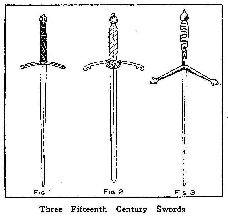
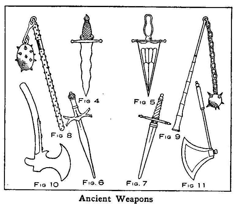
Ancient Weapons
Imitation swords, stilettos and battle-axes, put up as ornaments,
will look well if they are arranged on a shield which is hung
high up on a wall of a room or hall, says the English Mechanic,
London. The following described arms are authentic designs of the
original articles. A German sword of the fifteenth century is
shown in Fig. 1. This sword is 4 ft. long with the crossguard and
blade of steel. The imitation sword is made of wood and covered
with tinfoil to produce the steel color. The shape of the sword
is marked out on a piece of wood that is about 1/8 in. thick with
the aid of a straightedge and pencil, allowing a little extra
length on which to fasten the handle. Cut the sword out with a
saw and make both edges thin like a knife blade and smooth up
with sandpaper. The extra length for the handle is cut about 1
in. in width and 2 in. long. The handle is next carved and a
mortise cut in one end to receive the handle end of the blade. As
the handle is to represent copper, the ornamentations can be
built up of wire, string, small rope and round-headed nails, the
whole finally having a thin coat of glue worked over it with a
stiff bristle brush and finished with bronze paint.
The crossbar is flat and about 1 in. in width. Cut this out of a
piece of wood and make a center hole to fit over the extra length
on the blade, glue and put it in place. Fill the hole in the
handle with glue and put it on the blade. When the glue is
thoroughly dry, remove all the surplus with a sharp knife. Sheets
of tinfoil are secured for covering the blade. Cut two strips of
tinfoil, one about 1/2 in. wider than the blade and the other 1/4
in. narrower. Quickly cover one side of the blade with a thin
coat of glue and evenly lay on and press down the narrow strip of
tinfoil. Stick the wider strip on the other side in the same way,
allowing equal margin of tinfoil to overlap the edges of the
blade. Glue the overlapping edges and press them around on the
surface of the narrow strip. The crossguard must be covered in
the same manner as the blade. When the whole is quite dry, wipe
the blade up and down several times with light strokes using a
soft rag.
The sword shown in Fig. 2 is a two-handed Swiss sword about 4 ft.
in length, sharp on both edges with a handle of dark wood around
which is wound spirally a heavy piece of brass or copper wire and
held in place with round-headed brass nails. The blade and
crossbar are in imitation steel. The projecting ornament in the
center of the crossguard may be cut from heavy pasteboard and
bent into shape, then glued on the blade as shown.
In Fig. 3 is shown a claymore, or Scottish sword of the fifteenth
century. This sword is about 4 ft. long and has a wood handle
bound closely around with heavy cord. The crossbar and blade are
steel, with both edges sharp. A German poniard is shown in Fig.
4. This weapon is about 1 ft. long, very broad, with wire or
string’ bound handle, sharp edges on both sides. Another poniard
of the fourteenth century is shown in Fig. 5. This weapon is also
about 1 ft. long with wood handle and steel embossed blade. A
sixteenth century German poniard is shown in Fig. 6. The blade
and ornamental crossbar is of steel, with both edges of the blade
sharp. The handle is of wood. A German stiletto, sometimes called
cuirass breakers, is shown in Fig. 7. This stiletto has a wood
handle, steel crossbar and blade of steel with both edges sharp.
In Fig. 8 is shown a short-handled flail, which is about 2-1/2
ft. long with a dark handle of wood, studded with brass or steel
nails. A steel band is placed around the handle near the top. The
imitation of the steel band is made by gluing a piece of tinfoil
on a strip of cardboard and tacking it to the handle. A large
screw-eye is screwed into the top of the handle. The spiked ball
may be made of wood or clay. Cover the ball with some pieces of
linen, firmly glued on. When dry, paint it a dark brown or black.
A large screw-eye must be inserted in this ball, the same as used
on the end of the handle, and both eyes connected with a small
piece of rope twisted into shape. The rope is finished by
covering with tinfoil. Some short and heavy spike-headed nails
are driven into the ball to give it the appearance shown in the
illustration.
A Russian knout is shown in Fig. 9. The lower half of the handle
is of wood, the upper part iron or steel, which can be imitated
by covering a piece of wood that is properly shaped with tinfoil.
The whole handle can be made of wood in one piece, the lower part
painted black and the upper part covered with tinfoil. A
screw-eye is screwed into the upper end. A length of real iron or
steel chain is used to connect the handle with the ball. The ball
is made as described in Fig. 8. The spikes in the ball are about
1 in. in length. These must be cut from pieces of wood, leaving a
small peg at the end and in the center about the size of a No. 20
spike. The pegs are glued and inserted into holes drilled into
the ball.
In Fig. 10 is shown a Sclavonic horseman’s battle-axe which has a
handle of wood painted dark gray or light brown; the axe is of
steel. The blade is cut from a piece of 1/4-in. wood with a
keyhole saw. The round part is made thin and sharp on the edge.
The thick hammer side of the axe is built up to the necessary
thickness to cover the handle by gluing on pieces of wood the
same thickness as used for the blade, and gradually shaping off
to the middle of the axe by the use of a chisel, finishing with
sandpaper and covering with tinfoil. Three large, round-headed
brass or iron nails fixed into the front side of the handle will
complete the axe.
At the beginning of the sixteenth century horseman’s battle-axes
shaped as shown in Fig. 11 were used. Both handle and axe are of
steel. This axe is made similar to the one described in Fig. 10.
When the woodwork is finished the handle and axe are covered with
tinfoil.
How to Make a Round Belt Without Ends
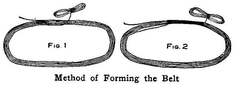
Method of Forming the Belt
A very good belt may be made by laying several strands of strong
cord, such as braided fishline, together as shown in Fig. 1 and
wrapping them as shown in Fig. 2. When wrapped all the way
around, the ends are tied and cut off. This will make a very good
flexible belt; will pull where other belts slip, and as the
tension members are all protected from wear, will last until the
wrapping member is worn through without being weakened.
Contributed by E. W. Davis, Chicago.
Old-Time Magic
The Growing Flower
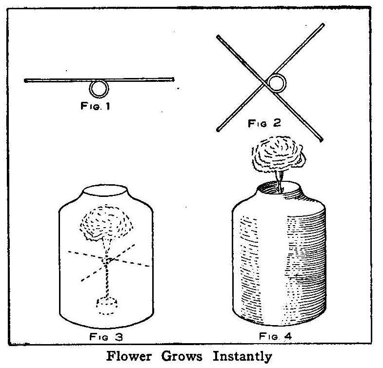
Flower Grows Instantly
This trick is performed with a wide-mouthed jar which is about 10
in. high. If an earthern jar of this kind is not at hand, use a
glass fruit jar and cover it with black cloth or paper, so the
contents cannot be seen. Two pieces of wire are bent as shown in
Fig. 1 and put together as in Fig. 2. These wires are put in the
jar, about one-third the way down from the top, with the circle
centrally located. The wires can be held in place by carefully
bending the ends, or using small wedges of wood.
Cut a wire shorter in length than the height of the jar and tie a
rose or several flowers on one end. Put a cork in the bottom of
the jar and stick the opposite end of the wire from where the
flowers are tied through the circle of the two wires and into the
cork. The dotted lines in Fig. 3 show the position of the wires
and flowers.
To make the flowers grow in an instant, pour water into the jar
at one side of the wide mouth. The cork will float and carry the
wire with the flowers attached upward, causing the flowers to
grow, apparently, in a few seconds’ time. Do not pour in too much
water to raise the flowers so far that the wire will be seen.
Contributed by A. S. Macdonald, Oakland, Calif.
Water and Wine Trick
This is an interesting trick based on the chemical properties of
acids and alkalies. The materials needed are: One glass pitcher,
filled with water, four glass tumblers, an acid, an alkali and
some phenolphthalein solution which can be obtained from your
local druggist. Before the performance, add a few drops of the
phenolphthalein to the water in the pitcher and rub a small
quantity of the alkali solution on the sides of two of the
tumblers and repeat, only using as large a quantity of the acid
as will escape notice on the remaining tumblers. Set the tumblers
so you will know which is which and proceed as follows: Take hold
of a prepared tumbler with the left hand and pour from the
pitcher, held in the right hand, some of the liquid. The liquid
turned into the glass will become red like wine. Set this full
tumbler aside and take the pitcher in the left hand and pour some
of the liquid in one of the tumblers containing the acid as it is
held in the right hand. There will be no change in color. Repeat
both parts in the same order then begin to pour the liquids
contained in the tumblers back into the pitcher in the order
reversed and the excess of acid will neutralize the alkali and
cause it to lose its color and in the end the pitcher will
contain a colorless liquid.
Contributed by Kenneth Weeks, Bridgeton, N.J.
Cheap Nails are Expensive
The life of iron shingle nails is about 6 years. An iron nail
cannot be used again in putting on a new roof. Solid zinc nails
last forever and can be used as often as necessary. As zinc is
much lighter than iron, the cost of zinc nails is only about
2-1/2 times that of iron nails.
Cutting Lantern Slide Masks
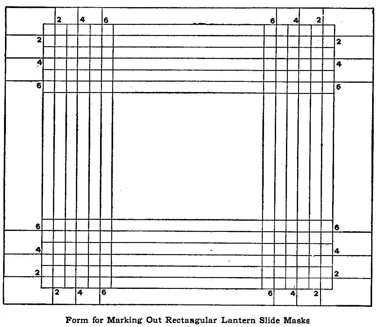
Form for Marking Out Rectangular Lantern Slide Masks
It has long been a puzzle to me why round cornered masks are
almost invariably used for lantern slides, when most works of art
are included within rectangular spaces, says a correspondent of
Photo Era. Certainly the present commercial masks are in very
poor taste. The worker who wishes to make the most of every slide
will do well to cut his own masks, not only because of the fact
just mentioned, but also because he can suit the size of the
opening to the requirements of each slide. Slides can be works of
art just as much as prints; so that masking a slide becomes just
as important as trimming a print, and equally worthy of
individual treatment. It is folly to give each slide a mask
opening of uniform size and shape.
When many slides are to be masked, it becomes tedious work to
treat each one separately, unless some special device is used.
The accompanying drawing shows a way to mark masks which is
simple, practical and costs nothing. The drawing is exactly
lantern slide size.
Lay the slide over such a guide and note the size of the opening
best suited to the picture. This will be determined by the
intersection of the ruled lines, which are numbered for
convenience in working. If the size wanted is No. 4 for width and
No. 2 for height, place the guide over a piece of black mask
paper and prick through the proper intersections with the point
of a pin. This outlines the desired opening, which may then be
cut out easily with a knife and straight edge.
The black paper from plate boxes and film rolls is excellent for
making masks. It should be cut up in pieces 3-1/4 by 4 in. and
kept ready for use at any time.
Relieving the Weight of a Talking Machine Reproducer
Too loud reproduction from a record, the scratching noise
sometimes heard and the forcing of the needle into a soft record,
because the extension arm and reproducer are too heavy, can be
remedied in the following manner: Attach a small ring to the
under side of the horn and use a rubber band to lift the
extending arm slightly.
Contributed by W. A. Jaquythe, Richmond, Cal.
How to Make a Thermometer Back in Etched Copper
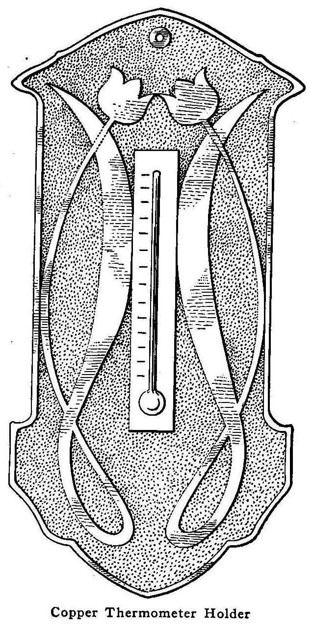
Copper Thermometer Holder
Etching copper is not a very difficult process. Secure a sheet of
No. 16 gauge copper of the width and length wanted for the back
of the thermometer. In the design shown the extreme width is
3-1/2 in. and the extreme length 7 in.
Draw a design. The one shown is merely suggestive. The worker may
change the outline or proportions as desired. The decoration,
too, may be changed. The essential thing is to keep a space upon
which to place the thermometer. This design is in what is known
as two-part symmetry. A line is drawn down the paper and one-half
of the outline and decoration worked out. This done, the paper is
folded along the center line, a piece of carbon paper is inserted
between the folds and the design transferred on the inner
surfaces by tracing with a pencil over the half of the outline
previously drawn. Trace the design and outline upon the metal,
using the carbon paper.
Cut out the outline with metal shears and file the edges smooth.
With a small brush and ordinary asphaltum or black varnish, paint
the design, the margin and the entire back of the metal. When
this coat has dried put on a second and then a third. The
asphaltum is to keep the acid into which the metal is to be
immersed later from eating any part of the metal but the
background. Two coats or more are needed to withstand the action
of the acid.
The acid bath is composed of nitric acid
and water, about half
and half, or, possibly, a little less acid than water, the
mixture being made by pouring the acid into the water, not the
water into the acid, which is dangerous. Keep this solution off
the hands and clothes, and do not inhale the fumes.
Put the asphalt-coated metal in the bath and allow it to remain
for four or five hours, depending upon the thickness of the metal
and the strength of the acid. With a stick, or a pair of old
tongs, take the metal out of the acid occasionally and examine it
to see how deep the acid has eaten it—1/32 in. is about right
for the No. 16 gauge.
When etched to the desired depth, remove the piece and with an
old knife’ scrape off the asphaltum. Finish the cleaning by
scrubbing with turpentine and a brush having stiff bristles.
If the metal is first covered with turpentine and then heated
over a flame, all the colors of the rainbow will appear on its
surface. These colors fade away in the course of a long time, but
they can be easily revived. Another way to get these colors is to
heat the metal and then plunge it into the acid bath quickly.
A green finish is obtained by painting the background with an
acid stain composed as follows: 1 part ammonia muriate; 3 parts
ammonia carbonate; 24 parts water. If one coat does not give the
depth of color desired, repeat as many times as is necessary,
allowing each coat time to dry before applying the next.
To “fix” this color so that it will not rub off, and to keep the
metal from tarnishing, apply a coat of banana oil or lacquer.
Thermometers of suitable size can be bought in either brass or
nickel. They have holes through their top and bottom ends through
which metal paper fasteners can be inserted, and these in turn
put through holes punched in the copper back.
To Make an Electric Piano
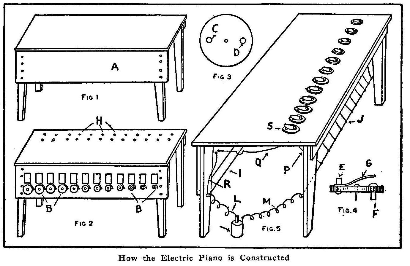
How the Electric Piano is Constructed
Make or buy a table, about 3 ft. long and 1 ft. or more wide, and
about 2-1/2 ft. high. Nail a board, A, Fig. 1, about 8 in. wide
and of the same length as the table, to the table, as shown in
the illustration. Paint the table any color desired.
Purchase a dozen or so battery electric bells (they are cheaper
if bought by the dozen) and screw them to the board, as in Fig.
2. Arrange the bells in the scale shown at B, Fig. 2. Bore two
holes near the posts of each bell for the wires to pass through.
Buttons for the bells may be purchased, but it is cheaper to make
them in the following way: Take a piece of wood and cut it round,
about 2-1/2 in. in diameter and 1/4 in. thick, Fig. 3, and bore
two holes, C and D, through it. Then get two posts, about 1 in.
long, (battery posts will do) and put them through the holes as
in Fig. 4. Cut out a piece of tin, 3/8 in. wide, punch a hole
through it and put in under post E, so that when it is pressed
down, it will touch post F. It may be either nailed or screwed
down.
Make two holes in the table for each button and its wires, as at
H, Fig. 2. Nail or screw the buttons to the table, as shown in
Fig. 5, with the wires underneath. The connections are simple: I,
Fig. 5, is a wire running from one end of the table to the other
end, attached to a post at each end; J is another wire attached
in the same way; L is the carbon wire running from the batteries
to I; M is the zinc wire running from the batteries to wire J; 0
indicates the batteries; P is a wire running from J to one post
of a button; Q is another wire running from the other post of the
button to one of the posts of the bell; R is a wire running from
I to one post of the bell. When the button S is pressed, the bell
will ring. Each button should be connected with its bell in the
same way.
Contributed by Vincent de Ybarrondo.
Imitation Arms and Armor—Part III
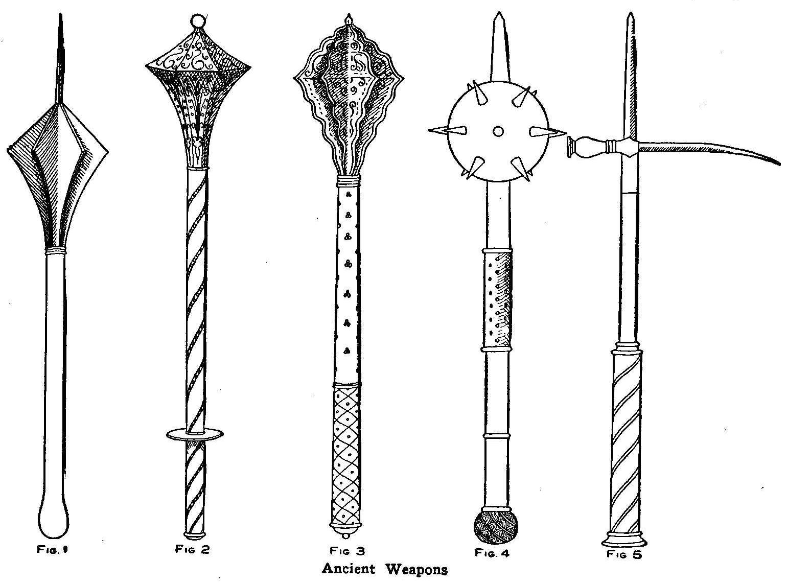
Ancient Weapons
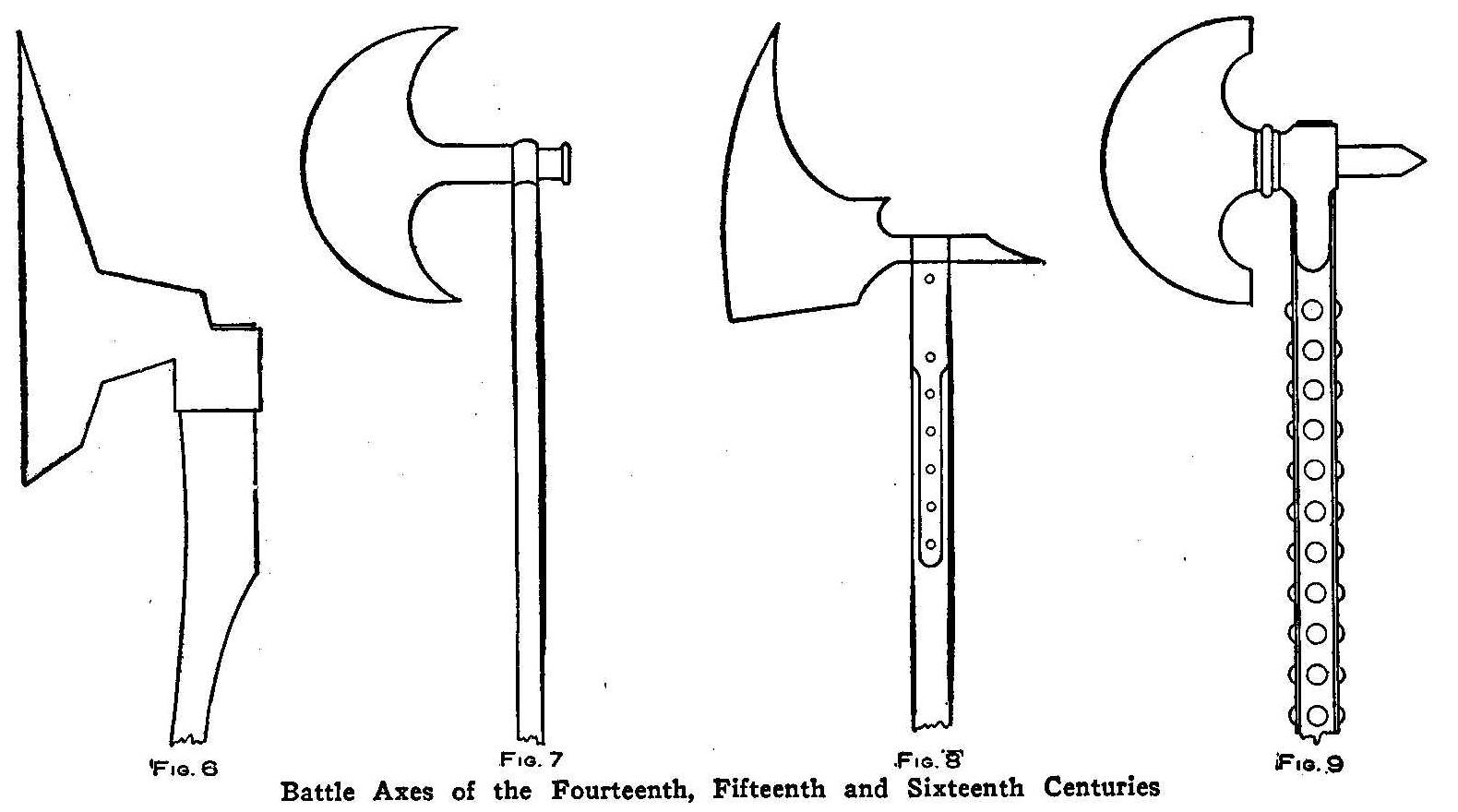
Battle Axes of the Fourteenth, Fifteenth and Sixteenth Centuries
Maces and battle-axes patterned after and made in imitation of
the ancient weapons which were used from the fourteenth to the
sixteenth century produce fine ornaments for the hall or den,
says the English Mechanic. The imitation articles are made of
wood, the steel parts represented by tinfoil stuck on with glue
and the ornaments carved out with a carving tool.
An English mace used about the middle of the fifteenth century is
shown in Fig. 1. The entire length of this weapon is about 24
in.; the handle is round with a four-sided sharp spike extending
out from the points of six triangular shaped wings. Cut the
handle and spike from one piece of wood and glue the wings on at
equal distances apart around the base of the spike. The two bands
or wings can be made by gluing two pieces of rope around the
handle and fastening it with tacks. These rings can be carved
out, but they are somewhat difficult to make. After the glue is
dry, remove all the surplus that has been pressed out from the
joints with the point of a sharp knife blade and then sandpaper
the surface of the wood to make it smooth. Secure some tinfoil to
cover the parts in imitation of steel. A thin coat of glue is
quickly applied to the surface of the wood and the tinfoil laid
on evenly so there will be no wrinkles and without making any
more seams than is necessary. The entire weapon, handle and all,
is to appear as steel.
An engraved iron mace of the fifteenth century is shown in Fig.
2. This weapon is about 22 in. long, mounted with an eight-sided
or octagonal head. It will be easier to make this mace in three
pieces, the octagonal head in one piece and the handle in two
parts, so that the circular shield shown at the lower end of the
handle can be easily placed between the parts. The circular piece
or shield can be cut from a piece of wood about 1/4 in. thick.
The circle is marked out with a compass. A hole is made through
the center for the dowel of the two handle parts when they are
put together. A wood peg about 2 in. long serves as the dowel. A
hole is bored in the end of both handle pieces and these holes
well coated with glue, the wood peg inserted in one of them, the
shield put on in place and handle parts put together and left for
the glue to set. The head is fastened on the end of the handle
with a dowel in the same manner as putting the handle parts
together.
The head must have a pattern sketched upon each side in pencil
marks, such as ornamental scrolls, leaves, flowers, etc. These
ornaments must be carved out to a depth of about 1/4 in. with a
sharp carving tool. If such a tool is not at hand, or the amateur
cannot use it well, an excellent substitute will be found in
using a sharp-pointed and red-hot poker, or pieces of heavy wire
heated to burn out the pattern to the desired depth. The handle
also has a scroll to be engraved. When the whole is finished and
cleaned Up, it is covered with tinfoil in imitation of steel. The
tinfoil should be applied carefully, as before mentioned, and
firmly pressed into the engraved parts with the finger tips or
thumb.
A French mace used in the sixteenth century is shown in Fig. 3.
This weapon is about 22 in. long and has a wood handle covered
with dark red cloth or velvet, the lower part to have a gold or
red silk cord wound around it, as shown, the whole handle
finished off with small brass-headed nails. The top has six
ornamental carved wings which are cut out, fastened on the handle
and covered with tinfoil, as described in Fig. 2.
Figure 4 shows a Morning Star which is about 26 in. long. The
spiked ball and the four-sided and sharp-pointed spike are of
steel. The ball may be made of clay or wood and covered with
tinfoil. The spikes are cut out of wood, sharp-pointed and
cone-shaped, the base having a brad to stick into the ball. The wood
spikes are also covered with tinfoil. The handle is of steel
imitation, covered in the middle with red cloth or velvet and
studded with large-headed steel nails.
A war hammer of the fifteenth century is shown in Fig. 5. Its
length is about 3 ft. The lower half of the handle is wood.
covered with red velvet, with a golden or yellow cord wound
spirally over the cloth. The upper half of the handle is steel,
also, the hammer and spike. The entire handle should be made of
one piece, then the hammer put on the base of the spike. The
spike made with a peg in its lower end and well glued, can be
firmly placed in position by the peg fitting in a hole made for
its reception in the top of the handle. Finish up the steel parts
with tinfoil.
The following described weapons can be constructed of the same
materials and built up in the same way as described in the
foregoing articles: A horseman’s short-handled battle-axe, used
at the end of the fifteenth century, is shown in Fig. 6. The
handle is of wood and the axe in imitation steel. Figure 7 shows
an English horseman’s battle-axe used at the beginning of the
reign of Queen Elizabeth. The handle and axe both are to be shown
in steel. A German foot soldier’s poleaxe used, at the end of the
fourteenth century is shown in Fig. 8. The handle is made of dark
wood and the axe covered with tinfoil. Figure 9 shows an English
foot soldier’s jedburgh axe of the sixteenth century. The handle
is of wood, studded with large brass or steel nails. The axe is
shown in steel. All of these axes are about the same length.
Playing Baseball with a Pocket Knife
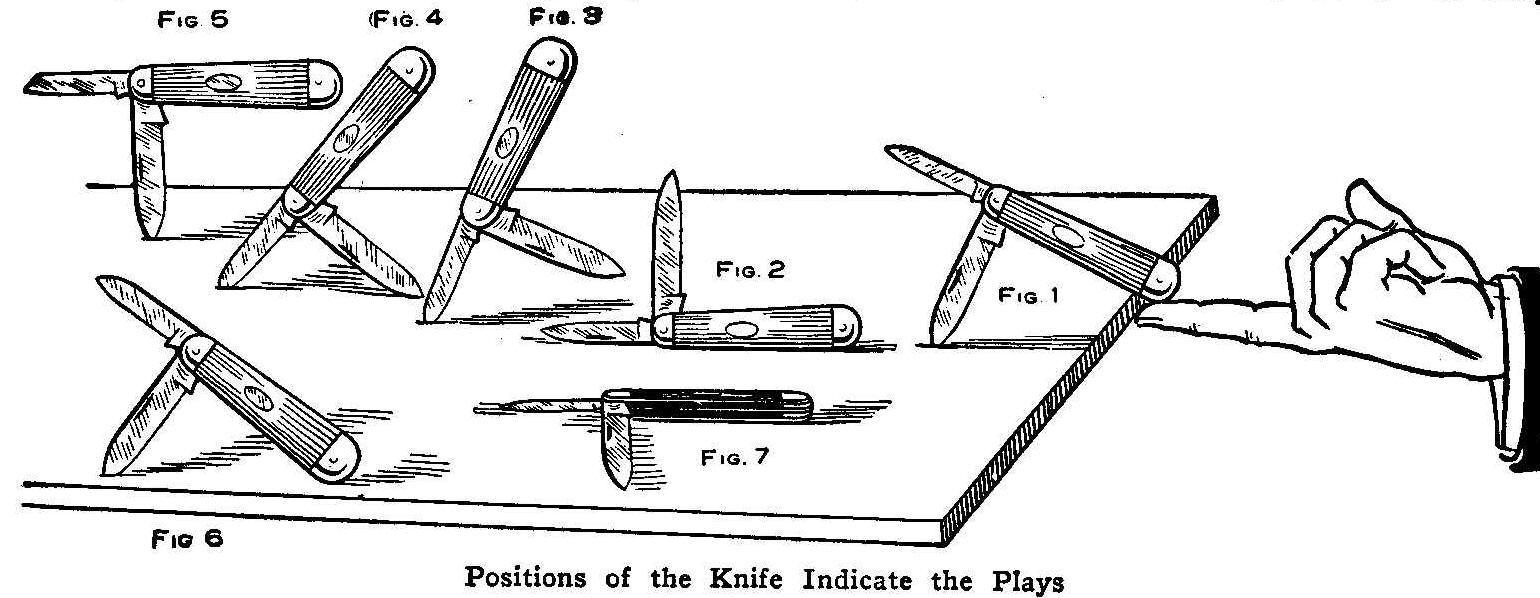
Positions of the Knife Indicate the Plays
Fig 1. Start
Fig 2. Foul
Fig 3. Home Run
Fig 4. Triple
Fig 5. Double
Fig 6. Single
Fig 7. Out
An interesting game of baseball can be played by two persons with
a common pocket knife on a rainy day or in the winter time when
the regular game cannot be played outdoors. The knife is opened
and loosely stuck into a board, as in Fig. 1, and with a quick
upward movement of the forefinger it is thrown into the air to
fall and land in one of the positions shown. The plays are
determined by the position of the knife after the fall.
A foul ball is indicated by Fig. 2, the knife resting on its
back. The small blade sticking in the board which holds the
handle in an upright position, as shown in Fig. 3, calls for a
home run. Both blades sticking in the board (Fig. 4), a
three-base hit. A two-base hit is made when the large blade
sticks in the board, Fig. 5. A one-base hit is secured when the
large blade and the end of the handle touch the board as in Fig.
6. The knife falling on its side (Fig. 7) calls for one out. Each
person plays until three outs have been made, then the other
plays, and so on for nine innings.
Contributed by Herbert Hahn, Chicago.
How to Remove Paper Stuck to a Negative
When making photographic prints from a negative, sometimes a drop
of moisture will cause the print to stick to the gelatine film on
the glass. Remove as much of the paper as can be readily torn off
and soak the negative in a fresh hypo bath of 3 or 4 oz. hypo to
1 pt. of water for an hour or two. Then a little gentle rubbing
with the finger-not the finger nail will remove anything adhering
to the film. It may be found that the negative is not colored. If
it is spotted at all, the negative must be washed for a few
minutes and placed in a combined toning and fixing bath, which
will remove the spots in a couple of hours. The negative must be
well washed after going through the solutions to take away any
trace of hypo.
Old-Time Magic
A Sack Trick
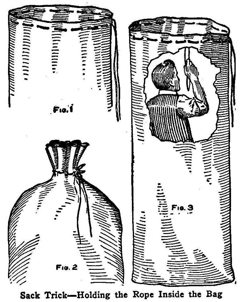
Sack Trick-Holding the Rope Inside the Bag
The magician appears accompanied by his assistant. He has a sack
similar to a meal bag only on a large scale. The upper end of
this bag is shown in Fig. 1, with the rope laced in the cloth. He
then selects several people from the audience as a committee to
examine the sack to see that there is absolutely no deception
whatever in its makeup. When they are satisfied that the bag or
sack is all right, the magician places his assistant inside and
drawing the bag around him he allows the committee to tie him up
with as many knots as they choose to make, as shown in Fig. 2.
The bag with its occupant is placed in a small cabinet which the
committee surround to see that there is no outside help. The
magician then takes his watch and shows the audience that in less
than 30 seconds his assistant will emerge from the cabinet with
the sack in his hand. This he does, the sack is again examined
and found to be the same as when it was first seen.
The solution is when the assistant enters the bag he pulls in
about 15 in. of the rope and holds it, as shown in Fig. 3, while
the committee is tying him up. As soon as he is in the cabinet he
merely lets out the slack thus making enough room for his body to
pass through. When he is out of the bag he quickly unties the
knots and then steps from his cabinet.
Contributed by J. F. Campbell, Somerville, Mass.
The Invisible Light
The magician places two common wax candles on a table, one of
them burning brightly, the other without a light. Members of the
audience are allowed to inspect both the table and the candles.
The magician walks over to the burning candle, shades the light
for a few seconds, turns to the audience with his hands a few
inches apart, showing that there is nothing between them, at the
same time saying that he has a light between his hands, invisible
to them (the audience), with which he is going to light the other
candle. He then walks over to the other candle, and, in plain
sight of the audience lights the candle apparently with nothing.
In reality the magician has a very fine wire in his hand which he
is heating while he bends over the lighted candle, and the
audience gaze on and see nothing. He turns to the other candle
and touches a grain of phosphorus
that has been previously concealed
in the wick with the heated wire, thus causing it to
light.
Contributed by C. Brown, New York City.
Using the Sun’s Light in a Magic Lantern
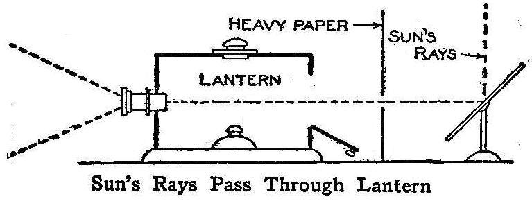
Sun’s Rays Pass Through Lantern
The light furnished with a small magic lantern does very well for
evening exhibitions, but the lantern can be used in the daytime
with good results by directing sunlight through the lens instead
of using the oil lamp.
A window facing the sun is selected and the shade is drawn almost
down, the remaining space being covered by a piece of heavy
paper. A small hole is cut in the paper and the lantern placed on
a table in front of the hole, the lamp having been removed and
the back opened. The lantern must be arranged so that the lens
will be on a horizontal line with the hole in the paper. A mirror
is then placed just outside of the window and at such an angle
that the beam of light is thrown through the hole in the paper
and the lens of the lantern.
The shades of the remaining windows are then drawn and the
lantern is operated in the usual way.
Contributed by L. B. Evans, Lebanon, Ky.
A Handy Drill Gauge
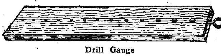
Drill Gauge
The accompanying sketch shows a simple drill gauge which will be
found very handy for amateurs. The gauge consists of a piece of
hard wood, 3/4 in. thick, with a width and length that will be
suitable for the size and number of drills you have on hand.
Drill a hole through the wood with each drill you have and place
a screw eye in one end to be used as a hanger. When you want to
drill a hole for a pipe, bolt, screw, etc., you take the gauge
and find what size drill must be used in drilling the
hole.
Contributed by Andrew G. Thome, Louisville, Ky.
Stove Polish
A good stove polish can be made by mixing together 1 lb. of
plumbago, 4 oz. of turpentine, 4 oz. of water and 1 oz. of sugar.
Mix well and apply with a cloth or brush.
A Home-Made Daniell Cell
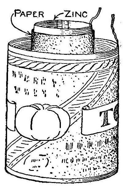
An effective Daniell galvanic cell may be constructed from
material costing very little money. A common tin tomato can with
a copper wire soldered to the top forms the jar and positive
electrode. A piece of discarded stove zinc rolled into an open
cylinder of about 1-1/2-in. diameter, 5 in. long, with a copper
wire soldered at one end forms the negative electrode.
To make the porous cell, roll a piece of heavy brown wrapping
paper, or blotting paper, into a tube of several thicknesses,
about 5 in. long with an internal diameter of 2 in. Tie the paper
firmly to prevent unrolling and close up one end with plaster of
paris 1/2 in. thick. It is well to slightly choke the tube to
better retain the plaster. The paper used must be unsized so that
the solution scan mingle through the pores.
Two liquids are necessary for the cell. Make a strong solution in
a glass or wooden vessel of blue vitriol in water. Dilute some
oil of vitriol (sulphuric acid)
with about 12 times its measure
of water and keep in a bottle when not in use. In making up the
solution, add the acid to the water with constant stirring. Do
not add water to the acid.
The cell is charged by placing the zinc in the paper tube and
both placed into the tin can. Connect the two wires and pour the
dilute acid into the porous cell around the zinc, and then
immediately turn the blue vitriol solution into the can outside
the paper cup.
A current generates at once and metallic copper begins to deposit
on the inside of the can. It is best to let the action continue
for a half hour or so before putting the cell into use. Several
hours working will be required before the film of copper becomes
sufficiently thick to protect the tin from corrosion when the
cell stands idle. For this reason it will be necessary to pour
out the blue vitriol solution into another receptacle immediately
after through using, as otherwise the tin would be soon eaten
full of holes. The porous cup should always be emptied after
using to prevent the diffusion of the blue vitriol solution into
the cup, and the paper tube must be well rinsed before putting
away to dry.
This makes one of the most satisfactory battery cells on account
of the constancy of its current, running for hours at a time
without materially losing strength, and the low cost of
maintenance makes it especially adapted for amateurs’ use. Its
current strength is about one volt, but can be made up into any
required voltage in series. A battery of a dozen cells should
cost not to exceed 50 cts. for the material, which will give a
strong, steady current, amply sufficient for all ordinary
experimental work.
A strong solution of common salt may be used in place of the oil
of vitriol in the porous cup, but is not so good.
Contributed by C. H. Denniston, Pulteney. N. Y.
A Home-Made Equatorial
By Harry Clark
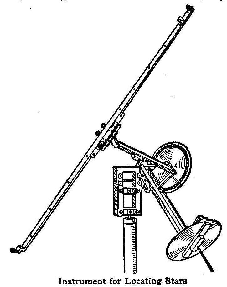
Instrument for Locating Stars
The ordinary equatorial is designed and built for the latitude of
the observatory where it is to be used. This is necessary since
the hour axis must point to the north pole of the heavens whose
elevation above the horizon is equal to the latitude of the
observer’s station. The final adjustment of an ordinary
equatorial is very tedious so that when once set up it is not to
be moved. This calls for a suitable house to protect the
instrument. It has been the aim of the writer to build a very
simple instrument for amateur work which would be adjustable to
any latitude, so easily set up ready for work and so portable
that it need not be left out of doors from one evening until the
next.
The instrument is mounted on a tripod or piece of iron pipe
carrying a short vertical rod of 3/8-in. steel. A rectangular
wooden frame with suitable bearings rotates about this shaft. The
frame has also two horizontal bearings carrying a short shaft to
the end of which the frame carrying the hour axis is firmly
clamped. By this arrangement of two perpendicular shafts the hour
axis may be directed to any point in the heavens without care as
to how the tripod or pipe is set up.
The frame for the hour axis is about 12 in. long with a bearing
at each end. The shaft which it carries is 1/4-in. steel,
carrying the hour circle at one end, and at the other the frame
for the declination axis which is similar to the other, but
somewhat lighter. The declination axis is also of 1/4-in. steel,
carrying at one end the declination circle and the pointer at the
other.
The entire frame of the instrument is made of cherry and it will
save the builder much time if he will purchase cherry “furniture”
which is used by printers and can be obtained from any printers’
supply company. It is best quality wood free from imperfections
in straight strips one yard long and of a uniform width of about
5/8 in. As to thickness, any multiple of 12-point (about 1/8 in.)
may be obtained, thus saving much work in fitting up joints.
Fifty cents will buy enough wood for an entire instrument. All
corners are carefully mortised and braced with small brass
angle-pieces. The frame is held together by small brass machine screws.
After much experimentation with bearings, it was found best to
make them in halves as metal bearings are usually made. The loose
half is held in place by guides on all four sides and is
tightened by two screws with milled nuts. A great deal of trouble
was experienced in boring out the bearings until the following
method was devised. One hole was bored as well as possible. The
bearing was then loosened and a bit run through it to bore the
other. Finally, a piece of shafting was roughened by rolling it
on a file; placed in both bearings and turned with a brace. The
bearings were gradually tightened until perfectly ground.
The declination axis must be perpendicular to both the hour axis
and the line of sight over the pointer. To insure this, a
positive adjustment was provided. The end of the shaft is clamped
in a short block of wood by means of a bearing like the ones
described. One end of the block is hinged to the axis frame,
while the other end is attached by two screws, one drawing them
together, the other holding them apart. The axis is adjusted by
turning these screws. Each shaft, save the one in the pipe, is
provided with this adjustment.
The pointer is of two very thin strips placed at right angles and
tapered slightly at each end. The clamp is attached as shown in
the illustration. The eye piece is a black iron washer supported
on a small strip of wood. The aperture should be 1/4 in., since
the pupil of the eye dilates very much in darkness. The error due
to large aperture is reduced by using a very long pointer which
also makes it possible to focus the eye upon the front sight and
the star simultaneously. The forward sight is a bright brass peg
illuminated by a tiny electric lamp with a reflector to shield
the eye. The pointer arranged in this way is a great improvement
over the hollow tube sometimes used, since it allows an
unobstructed view of the heavens while indicating the exact point
in question.
The circles of the instrument are of aluminum, attached to the
shafts by means of wooden clamps. They were nicely graduated by a
home-made dividing engine of very simple construction, and the
figures were engraved with a pantograph. The reading is
indicated by a cut on a small aluminum plate attached to a
pointer. The hour circle is divided into 24 parts and subdivided
to every four minutes. The figures are arranged so that when the
instrument is set up, the number of hours increases while the
pointer travels oppositely to the stars. The declination circle
is graduated from zero to 90 deg. in each direction from two
points 180 deg. apart. It is, adjusted to read zero when the
pointer and two axes are mutually perpendicular as shown in the
picture.
To adjust the instrument it is set up on the iron pipe and the
pointer directed to some distant object. All set screws,
excepting those on the declination axis, are tightened. Then the
pointer is carefully turned through 180 deg. and if it is not
again directed to the same point, it is not perpendicular to the
declination axis. When properly set it will describe a great
circle. With the declination axis in an approximately horizontal
position the place where the pointer cuts the horizon is noted.
The declination axis is then turned through 180 deg., when the
pointer should again cut at the same place. Proper adjustment
will cause it to do so. It is desirable that the hour circle
should read approximately zero when the declination axis is
horizontal, but this is not necessary for a reason soon to be
explained. All these adjustments, once carefully made, need not
be changed.
In using the instrument the hour axis can be directed to the
north pole by the following method. Point it approximately to the
north star. The pole is 1 deg. and 15 min. from the star on a
straight line from the star to “Mizar,” the star at the bend of
the handle in the Big Dipper. Turn the hour circle into a
position where the pointer can describe a circle through “Mizar.”
Only a rough setting is necessary. Now turn the pointer so that a
reading of 88 deg. 45 min. shows on the declination circle on
that side of 90 which is toward “Mizar.” When this is done, clamp
both axes and turn the shafts in the base until the pointer is
directed accurately to the north star. It is evident from a study
of the picture that the position of the small pointer which
indicates the reading on the hour circle is not independent of
the way in which the tripod or pipe is set up. It would then be
useless to adjust it carefully to zero when the pointer cuts the
“zenith” as is done with a large equatorial. Instead, the
adjustment is made by setting the clock or watch which is part of
the outfit. The pointer is directed to Alpha, Cassiopiae, and the
hour reading subtracted from 24 hours (the approximate right
ascension of the star) gives the time which the clock should be
set to indicate. All of these settings should require not more
than five minutes.
To find a star in the heavens, look up its declination and right
ascension in an atlas. Set the declination circle to its reading.
Subtract the clock time from the right ascension (plus 24 if
necessary) and set the hour circle to the result. The star will
then be seen on the tip of the pointer.
To locate a known star on the map, turn the pointer to the star.
Declination is read directly. Add the clock time to the hour
reading to get right ascension. If the result is more than 24
hours, subtract 24.
A Ground Glass Substitute
Ordinary plain glass coated with the following mixture will make
a good ground glass substitute: Dissolve 18 gr. of gum sandarac
and 4 gr. of gum mastic in 3-1/2 dr. of ether, then add 1 2-3
dr. benzole. If this will be too transparent, add a little more
benzole, taking care not to add too much. Cover one side of a
clear glass and after drying it will produce a perfect surface
for use as a ground glass in cameras.
Contributed by Ray E. Strosnider, Plain City, Ohio.
A Miniature War Dance
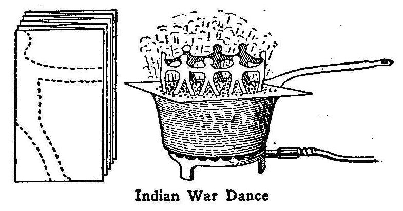
Indian War Dance
A piece of paper, 3 or 4 in. long, is folded several times, as
shown in the sketch, and the first fold marked out to represent
one-half of an Indian. Cut out all the folds at one time on the
dotted line and you will have as many men joined together as
there were folds in the paper. Join the hands of the two end men
with a little paste so as to form a circle of Indians holding
hands. The next thing to do is to punch holes in heavy cardboard
that is large enough to cover a pot or stew pan, and partially
fill the vessel with water. Set this covered vessel over a heat
and bring the water to a boiling point and then set the miniature
Indians on the perforated cover. The dance will begin.
If the Indians are decked out with small feathers to represent
the head gear and trailing plumes, a great effect will be
produced.
Contributed by Maurice Baudier, New Orleans, La.
Saving an Engine
Turning the water on before starting the gas engine may prevent
breaking a cylinder on a cold day.
Old-Time Magic
Removing 36 Cannon Balls from a Handbag
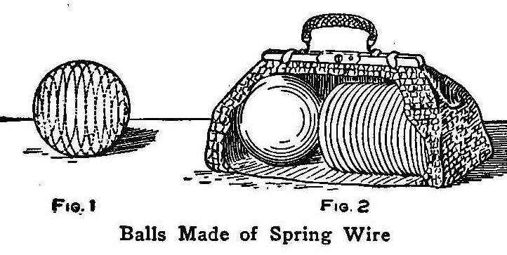
Balls Made of Spring Wire
The magician produces a small handbag and informs the audience
that he has it filled with 20-lb. cannon balls. He opens up the
bag and takes out a ball which he passes to the audience for
examination. The ball is found to be the genuine article. He
makes a few passes with the wand and produces another ball, and
so on until 36 of them lie on the floor.
In reality the first ball, which is the one examined, is the real
cannon ball, the others are spiral-spherical springs covered with
black cloth (Fig. 1). These balls can be pressed together in flat
disks and put in the bag, Fig. 2. without taking up any great
amount of space. When the spring is released it will fill out the
black cloth to represent a cannon ball that cannot be
distinguished from the real article.
Contributed by J. F. Campbell, Somerville, Mass.
A Rising Card Trick
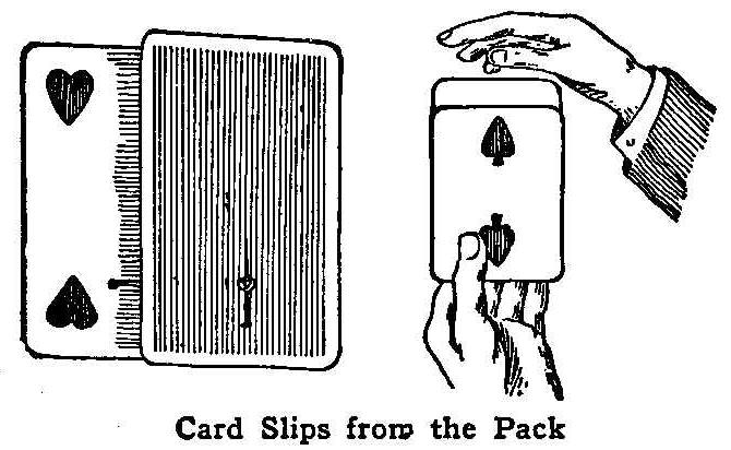
Card Slips from the Pack
A rising card trick can be accomplished with very little skill by
using the simple device illustrated. The only things needed are
four ordinary playing cards and a short rubber band. Pass one end
of the rubber band through one card and the other end through the
other card, as shown in the illustration, drawing the cards close
together and fastening the ends by putting a pin through them.
The remaining two cards are pasted to the first two so as to
conceal the pins and ends of the rubber band.
Put the cards with the rubber band in a pack of cards; take any
other card from the pack and show it to the audience in such a
way that you do not see and know the card shown. Return the card
to the pack, but be sure and place it between the cards tied together
with the rubber band. Grasp the pack between your thumb
and finger tightly at first, and by gradually loosening your hold
the card previously shown to the audience will slowly rise out of
the pack.
Contributed by Tomi O’Kawara, San Francisco, Cal.
Sliding Box Cover Fastener
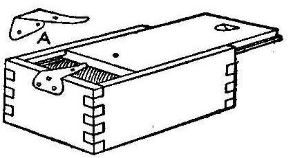
While traveling through the country as a watchmaker I found it
quite convenient to keep my small drills, taps, small brooches,
etc., In boxes having a sliding cover. To keep the contents from
spilling or getting mixed in my case I used a small fastener as
shown in the accompanying illustration, The fastener is made of
steel or brass and fastened by means of small screws or tacks on
the outside of the box. A hole is drilled on the upper part to
receive the pin that is driven into the sliding cover. This pin
should not stick out beyond the thickness of the spring, which is
bent up at the point so the pin will freely pass under it. The
pin can be driven through the cover to prevent it from being
pulled entirely out of the box.
Contributed by Herm Grabemann, Milwaukee, Wis.
How to Chain a Dog
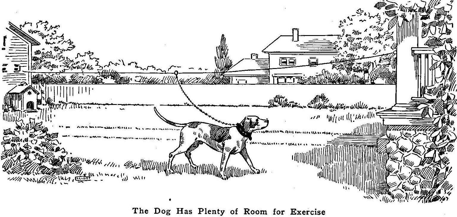
The Dog Has Plenty of Room for Exercise
A good way to chain a dog and give him plenty of ground for
exercise is to stretch a clothesline or a galvanized wire between
the house and barn on which is placed a ring large enough to
slide freely. The chain from the dog’s collar is fastened to the
ring. This method can also be used for tethering a cow or horse,
the advantage being the use of a short tie rope eliminating the
possibility of the animal becoming entangled.
Water-Color Box
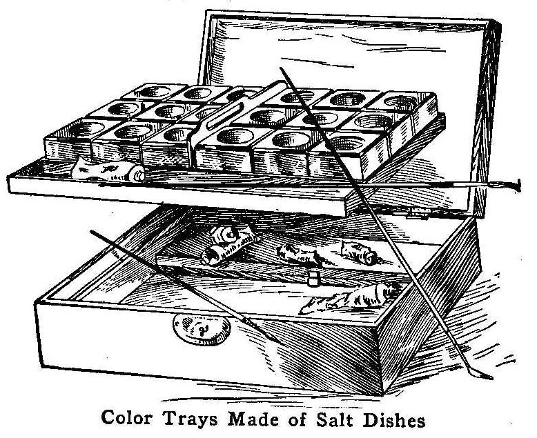
Color Trays Made of Salt Dishes
There are many different trays in the market for the purpose of
holding water colors, but they are either too expensive for the
average person or too small to be convenient. I do a great deal
of water-color work and always felt the need of a suitable color
dish. At last I found something that filled my want and suited my
pocketbook. I bought 22 individual salt dishes and made a box to
hold them, as shown in the illustration. This box has done good
service.
Some of the advantages are: Each color is in a separate dish
which can be easily taken out and cleaned; the dishes are deep
enough to prevent spilling the colors into the adjoining ones,
and the box can be made as big or as small as individual needs
require. The tray containing the color dishes and brushes rests
on 1/4-in. round pieces 2-1/4 in. from the bottom of the box,
thus giving ample store room for colors, prints, slides and extra
brushes.
Contributed by B. Beller, Hartford, Connecticut.
Saving Ink Pens
Ink usually corrodes pens in a short time. This can be prevented
by placing pieces of steel pens or steel wire in the ink, which
will absorb the acid and prevent it from corroding the pens.
A Plant-Food Percolator
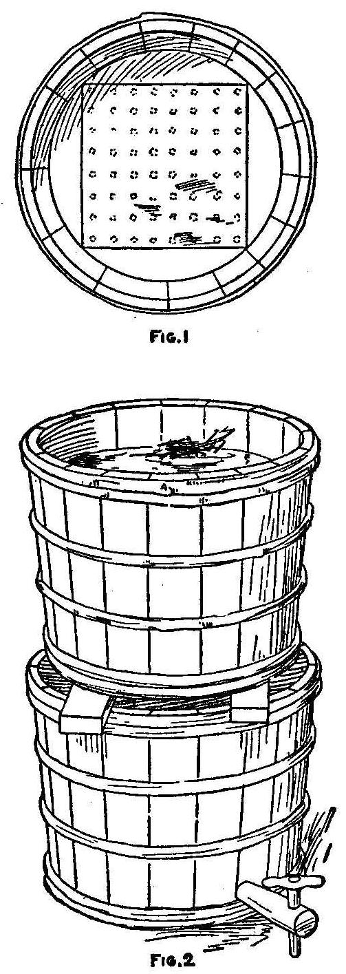
Obtain two butter tubs and bore a large number of 1/4-in. holes
in the bottom of one, then cover the perforated part with a piece
of fine brass gauze (Fig. 1), tacking the gauze well at the
corners. The other tub should be fitted with a faucet of some
kind—a wood faucet, costing 5 cents, will answer the purpose.
Put the first tub on top of the other with two narrow strips
between them (Fig. 2). Fill the upper tub, about three-fourths
full, with well packed horse manure, and pour water on it until
it is well soaked. When the water has percolated through into the
lower tub, it is ready to use on house and garden plants and is
better than plain water, as it adds both fertilizer and moisture.
Contributed by C. O. Darke, West Lynn, Mass.
Lathe Safety
Always caliper the work on a lathe while it is standing still.
Never use the ways of a lathe for an anvil or storage platform.
Folding Quilting-Frames
The frame in which the material is kept stretched when making a
quilt is usually too large to be put out of the way conveniently
when other duties must be attended to; and especially are the end
pieces objectionable. This can be remedied by hinging the ends so
they will fold underneath to the center. The end pieces are cut
in two at one-fourth their distance from each end, a hinge
screwed to the under side to hold them together, and a hook and
eye fastened on the other side to hold the parts rigid when they
are in use. When the ends are turned under, the frame is narrow
enough to be easily carried from one room to another, or placed
against a wall.
A Drip Shield for the Arms
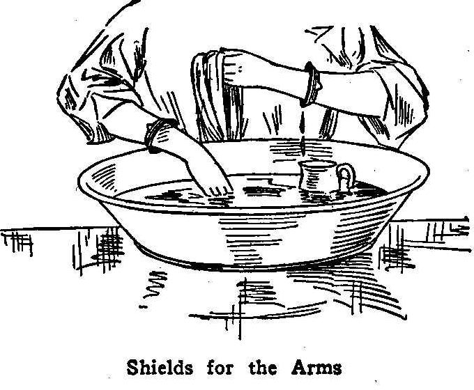
Shields for the Arms
When working with the hands in a pan of water, oil or other
fluid, it is very disagreeable to have the liquid run down the
arms, when they are raised from the pan, often to soil the
sleeves of a clean garment. A drip shield which will stop the
fluid and cause it to run back into the pan can be easily made
from a piece of sheet rubber or, if this is not available, from a
piece of the inner tube of a bicycle tire. Cut a washer with the
hole large enough to fit snugly about the wrist, but not so tight
as to stop the circulation of the blood. A pair of these shields
will always come in handy.
Contributed by L. M. Eifel, Chicago.
How to Cane Chairs
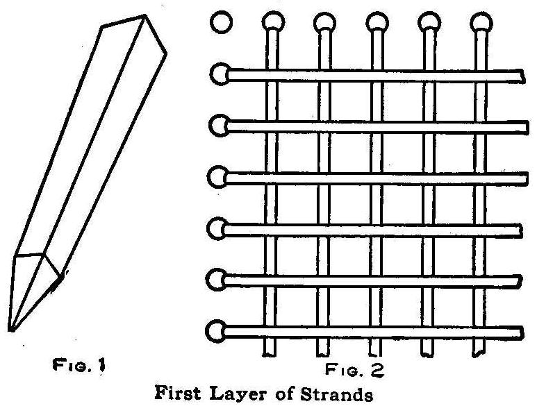
First Layer Of Strands
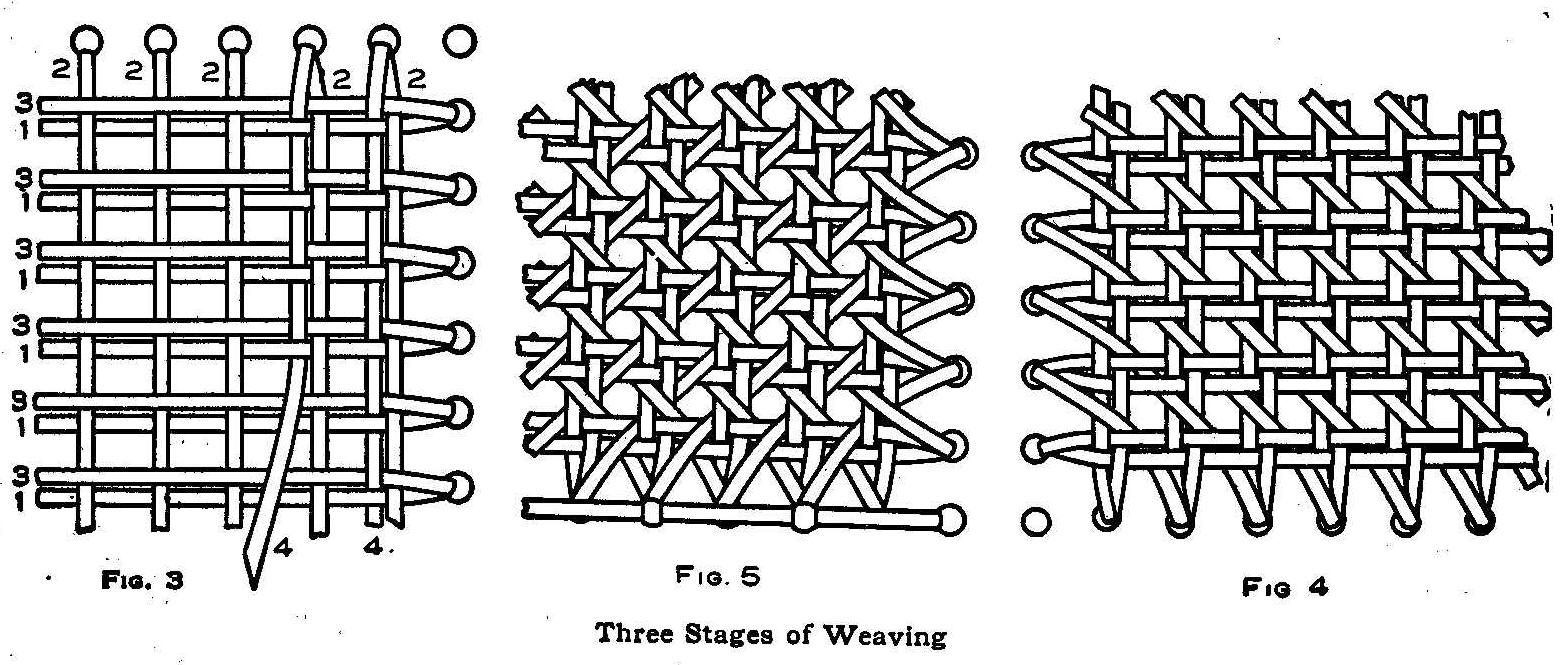
Three Stages of Weaving
There are but few households that do not have at least one or two
chairs without a seat or back. The same households may have some
one who would enjoy recaning the chairs if he only knew how to do
it, and also make considerable pin money by repairing chairs for
the neighbors. If the following directions are carried out, new
cane seats and backs can easily be put in chairs where they are
broken or sagged to an uncomfortable position.
The first thing necessary is to remove the old cane. This can be
done by turning the chair upside down and, with the aid of a
sharp knife or chisel, cutting the cane between the holes. After
this is done the old bottom can be pulled out. If plugs are found
in any of the holes, they should be knocked out. If the beginner
is in doubt about finding which holes along any curved sides
should be used for the cane running nearly parallel to the edge,
he may find it to his advantage to mark the holes on the under
side of the frame before removing the old cane.
The worker should be provided with a small sample of the old
cane. At any first-class hardware store a bundle of similar
material may be secured.
The cane usually comes in lengths of about 15 ft. and each bundle
contains enough to reseat several chairs. In addition to the
cane, the worker should provide himself with a piece of bacon
rind, a square pointed wedge, as shown in Fig. 1, and 8 or 10
round wood plugs, which are used for temporarily holding the ends
of the cane in the holes. A bucket of water should be supplied in
which to soak the cane just before weaving it. Several minutes
before you are ready to begin work, take four or five strands of
the cane, and, after having doubled them up singly into
convenient lengths and tied each one into a single knot, put them
into the water to soak. The cane is much more pliable and is less
liable to crack in bending when worked while wet. As fast as the
soaked cane is used, more of it should be put into the water.
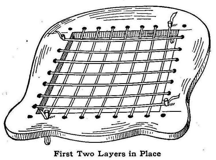
First Two Layers in Place
Untie one of the strands which has been well soaked, put about 3
or 4 in. down through the hole at one end of what is to be the
outside strand of one side and secure it in this hole by means
of one of the small plugs mentioned. The plug should not be
forced in too hard nor cut off, as it must be removed again. The
other end of the strand should be made pointed and passed down
through the hole at the opposite side, and, after having been
pulled tight, held there by inserting another plug. Pass the end
up through the next hole, then across and down, and hold while
the second plug is moved to the last hole through which the cane
was drawn. In the same manner proceed across the chair bottom.
Whenever the end of one strand is reached, it should be held by a
plug, and a new one started in the next hole as in the beginning.
No plugs should be permanently removed until another strand of
cane is through the same hole to hold the first strand in place.
After laying the strands across the seat in one direction, put in
another layer at right angles and lying entirely above the first
layer. Both of these layers when in place appear as shown in one
of the illustrations.
After completing the second layer, stretch the third one, using
the same holes as for the first layer. This will make three
layers, the first being hidden by the third while the second
layer is at right angles to and between the first and third. No
weaving has been done up to this time, nothing but stretching and
threading the cane through the holes. The cane will have the
appearance shown in Fig. 3. The next thing to do is to start the
cane across in the same direction as the second layer and begin
the weaving. The top or third layer strands should be pushed
toward the end from which the weaving starts, so that the strand
being woven may be pushed down between the first and third layers
and up again between pairs. The two first strands of the fourth
layer are shown woven in Fig. 3. During the weaving, the strands
should be lubricated with the rind of bacon to make them pass
through with ease. Even with this lubrication, one can seldom
weave more than half way across the seat with the pointed end
before finding it advisable to pull the remainder of the strand
through. After finishing this fourth layer of strands, it is
quite probable that each strand will be about midway between its
two neighbors instead of lying close to its mate as desired, and
here is where the square and pointed wedge is used. The wedge is
driven down between the proper strands to move them into place.
Start at one corner and weave diagonally, as shown in Fig. 4,
making sure that the strand will slip in between the two which
form the corner of the square in each case. One more weave across
on the diagonal and the seat will be finished except for the
binding, as shown in Fig. 5. The binding consists of one strand
that covers the row of holes while it is held down with another
strand, a loop over the first being made every second or third
hole as desired. It will be of great assistance to keep another
chair with a cane bottom at hand to examine while recaning the
first chair.
Contributed by M. R. W.
Repairing a Cracked Composition Developing Tray
Fill the crack with some powdered rosin and heap it up on the
outside. Heat a soldering-iron or any piece of metal enough to
melt the rosin and let it flow through the break. When cool, trim
off the surplus rosin. If handled with a little care, a tray
repaired in this manner will last a long time. The chemicals will
not affect the rosin.
Contributed by E. D. Patrick, Detroit, Michigan.
How to Lay Out a Sundial
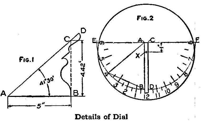
Details of Dial
The sundial is an instrument for measuring time by using the
shadow of the sun. They were quite common in ancient times before
clocks and watches were invented. At the present time they are
used more as an ornamentation than as a means of measuring time,
although they are quite accurate if properly constructed. There
are several different designs of sundials, but the most common,
and the one we shall describe in this article, is the horizontal
dial. It consists of a flat circular table, placed firmly on a
solid pedestal and having a triangular plate of metal, Fig. 1,
called the gnomon, rising from its center and inclined toward the
meridian line of the dial at an angle equal to the latitude of
the place where the dial is to be used. The shadow of the edge of
the triangular plate moves around the northern part of the dial
from morning to afternoon, and thus supplies a rough measurement
of the hour of the day.
Table No. 1.
Height of stile in inches for a 5 in.
base, for various latitudes
| Latitude | Height |
| 25° | 2.33 |
| 26° | 2.44 |
| 27° | 2.55 |
| 28° | 2.66 |
| 30° | 2.89 |
| 32° | 3.12 |
| 34° | 3.37 |
| 36° | 3.63 |
| 38° | 3.91 |
| 40° | 4.20 |
| 42° | 4.50 |
| 44° | 4.83 |
| 46° | 5.18 |
| 48° | 5.55 |
| 50° | 5.96 |
| 52° | 6.40 |
| 54° | 6.88 |
| 56° | 7.41 |
| 58° | 8.00 |
| 60° | 8.66 |
The style or gnomon, as it always equals the latitude of the
place, can be laid out as follows: Draw a line AB, Fig. 1, 5 in.
long and at the one end erect a perpendicular BC, the height of
which is taken from table No. 1. It may be necessary to
interpolate for a given latitude, as for example, lat. 41°-30′.
From table No. 1 lat. 42° is 4.5 in. and for lat. 40°, the next
smallest, it is 4.2 in. Their difference is .3 in. for 2°, and
for 1° it would be .15 in. For 30′ it would be 1/2 of 1° or .075
in. All added to the lesser or 40°, we have 4.2+.15+.075 in.=
4.42 in. as the height of the line BC for lat. 41 °-30′. If you
have a table of natural functions, the height of the line BC, or
the style, is the base (5 in. in this case) times the tangent of
the degree of latitude. Draw the line AD, and the angle BAD is
the correct angle for the style for the given latitude. Its
thickness, if of metal, may be conveniently from 1/8 to 1/4 in.;
or if of stone, an inch or two, or more, according to the size of
the dial. Usually for neatness of appearance the back of the
style is hollowed as shown. The upper edges which cast the
shadows must be sharp and straight, and for this size dial (10
in. in diameter) they should be about 7-1/2 in. long.
To lay out the hour circle, draw two parallel lines AB and CD,
Fig. 2, which will represent the base in length and thickness.
Draw two semi-circles, using the points A and C as centers, with
a radius of 5 in. The points of intersection with the lines AB
and CD will be the 12 o’clock marks. A line EF drawn through the
points A and C, and perpendicular to the base or style, and
intersecting the semicircles, gives the 6 o’clock points. The
point marked X is to be used as the center of the dial. The
intermediate hour and half-hour lines can be plotted by using
table No. 2 for given latitudes, placing them to the right or
left of the 12-o’clock points. For latitudes not given,
interpolate in the same manner as for the height of the style.
The 1/4-hour and the 5 and 10-minute divisions may be spaced with
the eye or they may be computed.
Table NO. 2.
Chords in inches for a 10 in. circle Sundial.
| Lat | Hours Of Day | ||||||||||
| 12-30 | 1 | 1-30 | 2 | 2-30 | 3 | 3-30 | 4 | 4-30 | 5 | 5-30 | |
| 11-30 | 11 | 10-30 | 10 | 9-30 | 9 | 8-30 | 8 | 7-30 | 7 | 6-30 | |
| 25° | .28 | .56 | .870 | 1.19 | 1.57 | 1.99 | 2.49 | 3.11 | 3.87 | 4.82 | 5.93 |
| 30 | .33 | .66 | 1.02 | 1.40 | 1.82 | 2.30 | 2.85 | 3.49 | 4.26 | 5.14 | 6.10 |
| 35 | .38 | .76 | 1.16 | 1.59 | 2.06 | 2.57 | 3.16 | 3.81 | 4.55 | 5.37 | 6.23 |
| 40 | .42 | .85 | 1.30 | 1.77 | 2.27 | 2.82 | 3.42 | 4.07 | 4.79 | 5.55 | 6.32 |
| 45 | .46 | .94 | 1.42 | 1.93 | 2.46 | 3.03 | 3.64 | 4.29 | 4.97 | 5.68 | 6.39 |
| 50 | .50 | 1.01 | 1.53 | 2.06 | 2.68 | 3.21 | 3.82 | 4.46 | 5.12 | 5.79 | 6.46 |
| 55 | .54 | 1.08 | 1.63 | 2.19 | 2.77 | 3.37 | 3.98 | 4.60 | 5.24 | 5.87 | 6.49 |
| 60 | .57 | 1.14 | 1.71 | 2.30 | 2.89 | 3.49 | 4.10 | 4.72 | 5.34 | 5.93 | 6.52 |
Table No. 3
Corrections in minutes to change Sun time to local mean time; add
those marked +, subtract those Marked – from Sundial time.
| Day of month | 1 | 10 | 20 | 30 |
| January | +3 | +7 | +11 | +13 |
| February | +14 | +14 | +14 | 0 |
| March | +13 | +11 | +8 | +5 |
| April | +4 | +2 | -1 | -3 |
| May | -3 | -4 | -4 | -3 |
| June | -3 | +1 | +1 | +3 |
| July | +3 | +5 | +6 | +6 |
| August | +6 | +5 | +3 | +1 |
| September | +0 | -3 | -6 | -10 |
| October | -10 | -13 | -15 | -16 |
| November | -16 | -16 | -14 | -11 |
| December | -11 | -7 | -3 | +2 |
When placing the dial in position, care must be taken to get it
perfectly level and have the style at right angles to the dial
face, with its sloping side pointing to the North Pole. An
ordinary compass, after allowing for the declination, will enable
one to set the dial, or it may be set by placing it as near north
and south as one may judge and comparing with a watch set at
standard time. The dial time and the watch time should agree
after the watch has been corrected for the equation of time from
table No. 3, and for the difference between standard and local
time, changing the position of the dial until an agreement is
reached. Sun time and standard time agree only four times a year,
April 16, June 15, Sept. 2 and Dec. 25, and on these dates the
dial needs no correction. The corrections for the various days
of the month can be taken from Table 3. The + means that the
clock is faster, and the – means that the dial is faster than the
sun. Still another correction must be made which is constant for
each given locality. Standard time is the correct time for
longitude 75° New York, 90° Chicago, 105° Denver and 120° for San
Francisco. Ascertain in degrees of longitude how far your dial is
east or west of the nearest standard meridian and divide this by
15, reducing the answer to minutes and seconds, which will be the
correction in minutes and seconds of time. If the dial is east of
the meridian chosen, then the watch is slower; if west, it will
be faster. This correction can be added to the values in table
No. 3, making each value slower when it is east of the standard
meridian and faster when it is west.
The style or gnomon with its base can be made in cement and set
on a cement pedestal which has sufficient base placed in the
ground to make it solid.
The design of the sundial is left to the ingenuity of the maker.
Contributed by J. E. Mitchell, Sioux City, Iowa.
Imitation Arms and Armor-Part IV
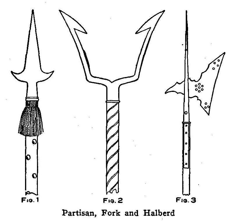
Partisan, Fork and Halberd
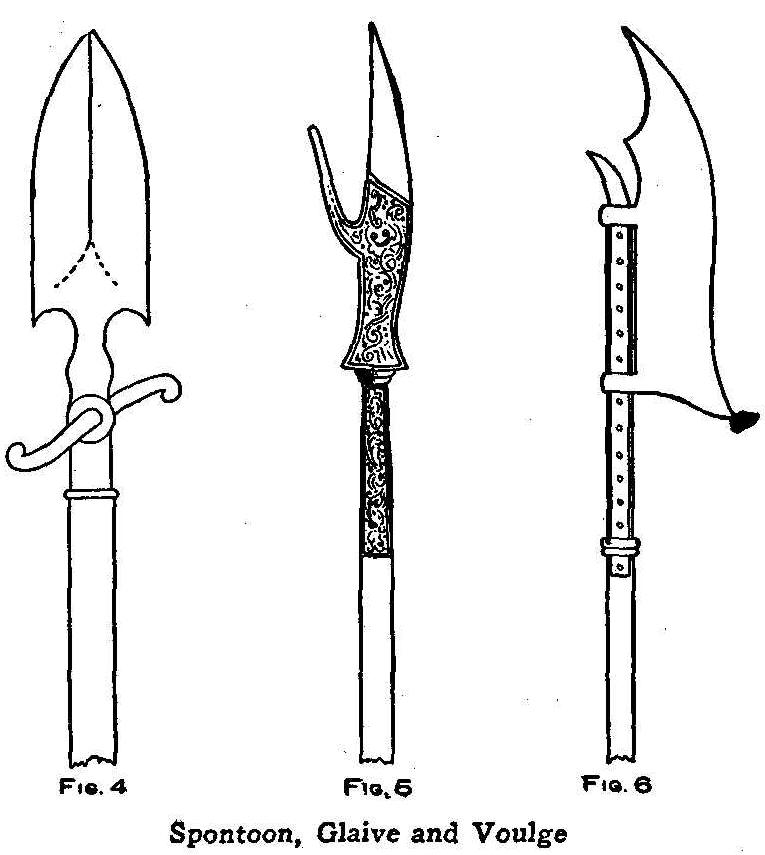
Spontoon, Glaive and Voulge
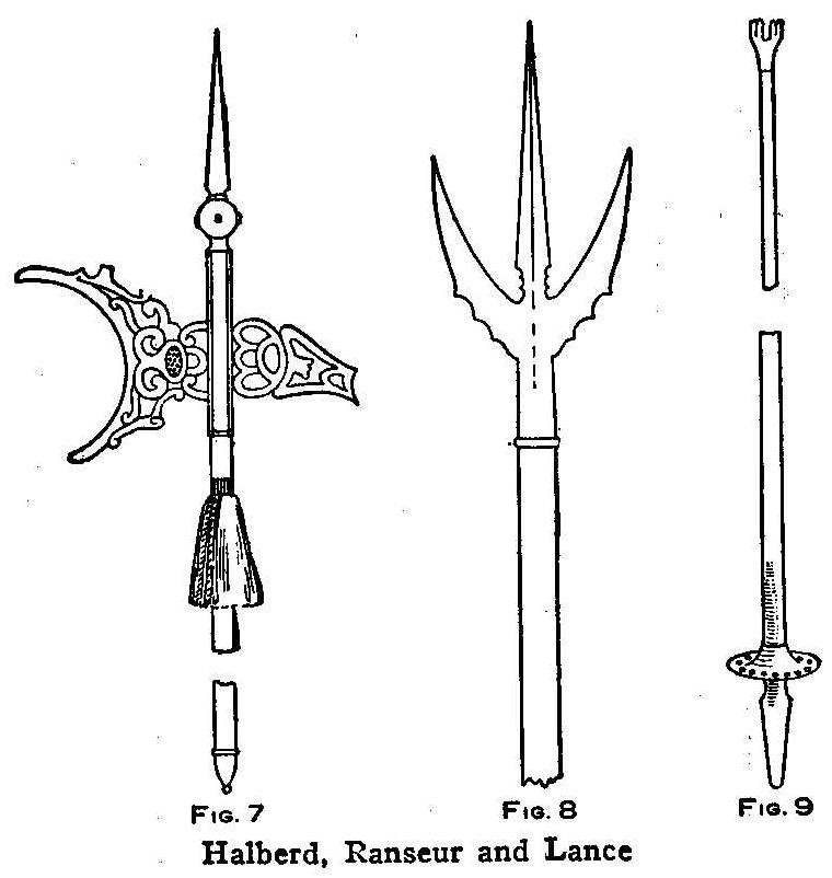
Halberd, Ranseur and Lance
The ancient arms of defense as shown in the accompanying
illustrations make good ornaments for the den if they are cut
from wood and finished in imitation of the real weapon. The
designs shown represent original arms of the sixteenth and
seventeenth centuries. As they are the genuine reproductions,
each article can be labelled with the name, adding to each piece
interest and value, says the English Mechanic, London.
Each weapon is cut from wood. The blades of the axes and the
cutting edges of the swords are dressed down and finished with
sandpaper and the steel parts represented by covering the wood
with tinfoil. When putting on the tinfoil, brush a thin coat of
glue on the part to be covered and quickly lay on the foil. If a
cutting edge is to be covered the tinfoil on one side of the
blade must overlap the edge which is pasted on the opposite side.
The other side is then covered with the tinfoil of a size that
will not quite cover to the cutting edge. After laying the foil
and allowing time for the glue to dry, wipe the surface with
light strokes up and down several times using a soft piece of
cloth.
A French partisan of the sixteenth century is shown in Fig. 1.
The weapon is 6-1/2 ft. long with a round handle having the same
circumference for the entire length which is covered with crimson
cloth or velvet and studded all over with round-headed brass
nails. The spear head is of steel about 15 in. long from the
point where it is attached to the handle. The widest part of the
blade from spear to spear is about 8 in. The length of the tassel
or fringe is about 4 in.
Figure 2 shows a German military fork of the sixteenth century,
the length of which is about 5 ft. with a handle of wood bound
with heavy cord in a spiral form and the whole painted a dark
color. The entire length of the fork from the handle to the
points is about 10 in., and is covered with tinfoil in imitation
of steel.
A Swiss halberd of the sixteenth century is shown in Fig. 3. This
combination of an axe and spear is about 7 ft. long from the
point of the spear to the end of the handle, which is square. The
spear and axe is of steel with a handle of plain dark wood. The
holes in the axe can be bored or burned out with red-hot iron
rods, the holes being about 1/4 in. in diameter.
Figure 4 shows an Austrian officers’ spontoon, used about the
seventeenth century. It is about 6 ft. long with a round wooden
handle. The spear head from its point to where fixed on the
handle is about 9 in. long. The edges are sharp. The cross bar
which runs through the lower end of the spear can be made in two
pieces and glued into a hole on each side. The length of this bar
is about 5 in. The small circular plate through which the bar is
fixed can be cut from a piece of cardboard and glued on the
wooden spear.
A gisarm or glaive, used by Italians in the sixteenth century, is
shown in Fig. 5. The entire length is about 6-1/2 ft. The blade
is engraved steel with a length of metal work from the point of
the spear to where it joins the handle or staff of about 18 in.
It has a round wooden handle painted black or dark brown. The
engraved work must be carved in the wood and when putting the
tinfoil on, press it well into the carved depressions.
Figure 6 shows a Saxon voulge of the sixteenth century, 6 ft.
long, with a round wood handle and a steel axe or blade, sharp on
the outer edge and held to the handle by two steel bands, which
are a part of the axe. The bands can be made of cardboard and
glued on to the wood axe. These bands can be made very strong by
reinforcing the cardboard with a piece of canvas. A small curved
spear point is carved from a piece of wood, covered with tinfoil
and fastened on the end of the handle as shown. The band of metal
on the side is cut from cardboard, covered with tinfoil and
fastened on with round-headed brass or steel nails.
A very handsome weapon is the German halberd of the sixteenth
century which is shown in Fig. 7. The entire length is about
6-1/2 ft., with a round wooden handle fitted at the lower end
with a steel ornament. The length of the spear point to the lower
end where it joins on to the handle is 14 in. The extreme width
of the axe is 16 or 17 in. The outer and inner edges of the
crescent-shaped part of the axe are sharp. This axe is cut out
with a scroll or keyhole saw and covered with tinfoil.
An Italian ranseur of the sixteenth century is shown in Fig. 8.
This weapon is about 6 ft. long with a round staff or handle. The
entire length of the metal part from the point of the spear to
where it joins the staff is 15 in. The spear is steel, sharp on
the outer edges.
Figure 9 shows a tilting lance with vamplate used in tournaments
in the sixteenth century. The wood pole is covered with cloth or
painted a dark color. At the end is a four-pronged piece of
steel. The vamplate can be made of cardboard covered with tinfoil
to represent steel and studded with brass nails. The extreme
length is 9 ft.
The tassels or fringe used in decorating the handles can be made
from a few inches of worsted fringe, about 4 in. long and wound
around the handle or staff twice and fastened with brass-headed
nails.
An Emergency Babbitt Ladle
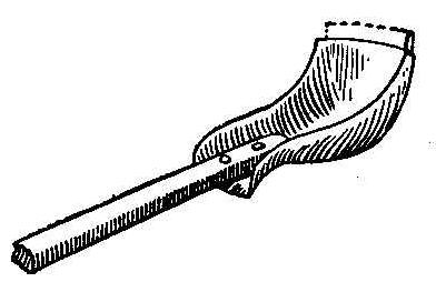
Take an old stove leg and rivet a handle on it and then break the
piece off which fastens on the stove. The large and rounding part
of the leg makes the bowl of the ladle. This ladle will be found
convenient for melting babbitt or lead.
Contributed by R. H. Workman, Loudonville, Ohio.
How to Make Japanese Portieres
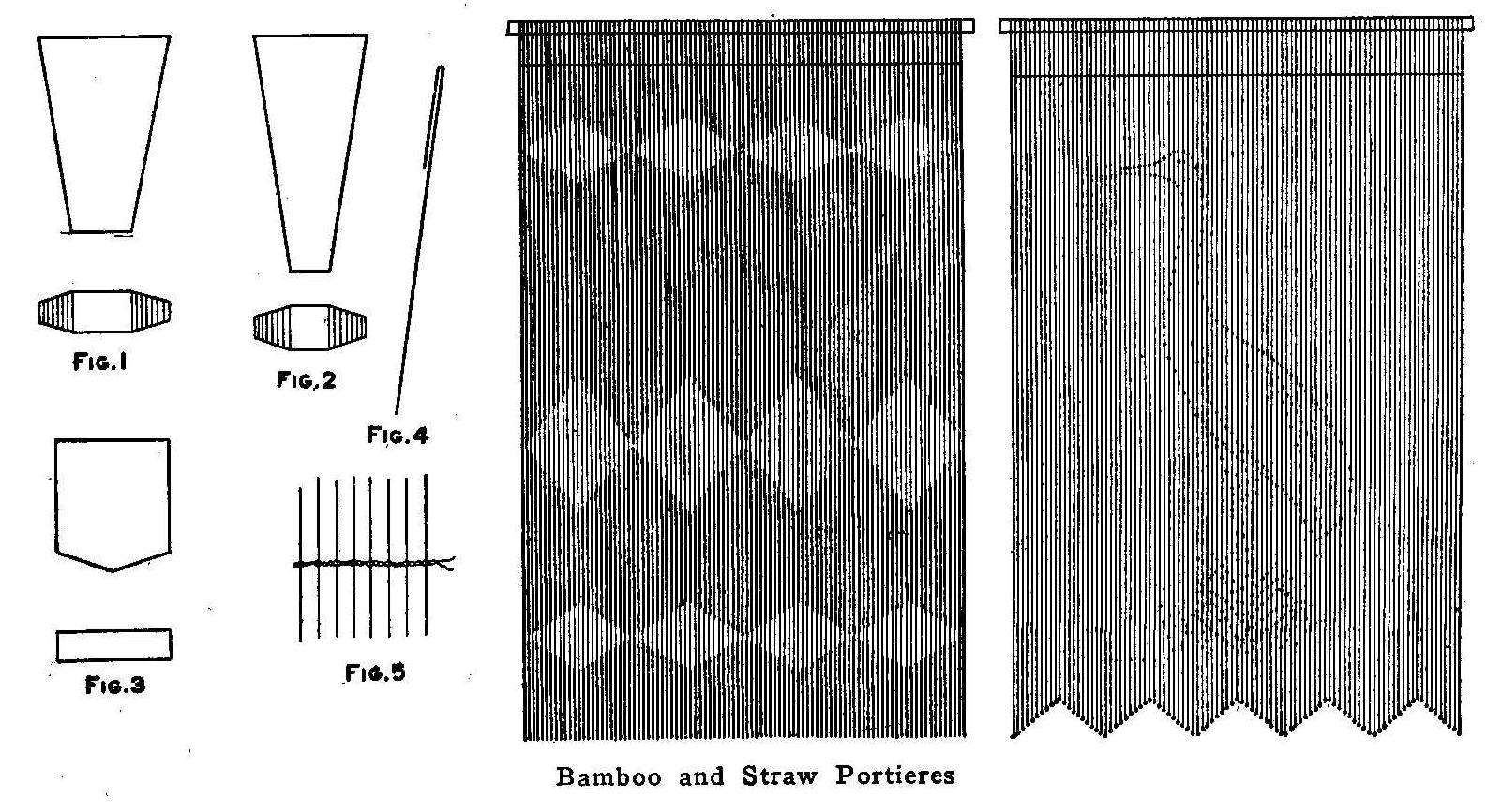
Bamboo and Straw Portieres
These very useful and ornamental draperies can be easily made at
home by anyone possessing a little ingenuity. They can be made of
various materials, the most durable being bamboo, although beads
of glass or rolled paper will produce good results. Substances
such as straw, while readily adaptable and having a neat
appearance, are less durable and will quickly show wear. The
paper beads are easily made as shown in Figs. 1, 2 and 3. In
Figs. 1 and 2 are shown how the paper is cut tapering, and as it
appears after rolling and gluing down the ends. A straight paper
bead is shown in Fig. B.
The first step is to select the kind of beads desired for
stringing and then procure the hanging cord. Be sure to get a
cord of such size that the beads will slip on readily and yet
have the least possible lateral movement. This is important to
secure neatness. One end of each cord is tied to a round piece of
wood, or in holes punched in a leather strap. Iron or brass rings
can be used if desired.
Cut all the cords the same length, making allowance for the
number of knots necessary to produce the design selected. Some
designs require only one knot at the bottom. It is best to make a
rough sketch of the design on paper. This will greatly aid the
maker in carrying on the work.
When the main part of the screen is finished, the cross cords,
used for spacing and binding the whole together, are put in
place. This is done with a needle made from a piece of small
wire, as shown in Fig. 4. The cross cords are woven in as shown
in Fig. 5. As many of these cross cords can be put in as desired,
and if placed from 6 to 12 in. apart, a solid screen will be made
instead of a portiere. The twisted cross cords should be of such
material, and put through in such manner that they will not be
readily seen. If paper beads are used they can be colored to suit
and hardened by varnishing.
The first design shown is for using bamboo. The cords are knotted
to hold the bamboo pieces in place. The finished portiere will
resemble drawn work in cloth. Many beautiful hangings can be
easily fashioned.
The second design is to be constructed with a plain ground of
either straw, bamboo or rolled paper. The cords are hung upon a
round stick with rings of metal to make the sliding easy. The
design is made by stringing beads of colored glass at the right
places between the lengths of ground material. One bead is placed
at the extreme end of each cord. The rows of twisted cord placed
at the top keep the strings properly spaced.
Contributed by Geo. M. Harrer, Lockport, New York.
Makeshift Camper’s Lantern
Lantern Made of Old Cans
While out camping, our only lantern was accidentally smashed
beyond repair, and it was necessary to devise something that
would take its place. We took an empty tomato can and cut out the
tin, 3 in. wide, for a length extending from a point 2 in. below
the top to within 1/4 in. of the bottom. Each side of the cutout
A was bent inward in the shape of a letter S, in which was
placed a piece of glass. Four V-shaped notches were cut, as shown
at B, near the top of the can and their points turned outward. A
slit was cut in the bottom, shaped as shown at C, and the pointed
ends thus formed were turned up to make a place for holding the
base of a candle. A larger can was secured and the bottom
perforated. This was turned over the top of the other can. A
heavy wire was run through the perforations and a short piece of
broom handle used to make a bail.
Contributed by Maurice Baudier, New Orleans, La.
New Tires for Carpet-Sweeper Wheels
The rubber tires on carpet-sweeper wheels often become so badly
worn and stretched that they fail to grip the carpet firmly enough
to run the sweeper. To remedy this, procure some rubber tape a
little wider than the rims of the old wheels, remove the old
rubber tires and wind the tape on the rims to the proper
thickness. Trim the edges with a sharp knife and rub on some
chalk or soapstone powder to prevent the tape from sticking to
the carpet. A sweeper treated in this manner will work as well as
a new one.
Contributed by W. H. Shay, Newburgh, N. Y.
Gauntlets on Gloves
When the fingers or palms of gloves with gauntlets wear out, do
not throw away the gloves, but cut off the gauntlets and procure
a pair of gloves with short wrists to which the old gauntlets can
be sewn after the wrist bands have been removed from the new
gloves. The sewing may be done either by hand or on a machine,
gathering in any fullness in the bellows of the cuff on the under
side. A pair of gauntlets will outwear three or four pairs of
gloves.
Contributed by Joseph H. Sanford, Pasadena, Cal.
How to Make an Ornamental Brass Flag
The Finished Flag
The outlines of the flag—which may be of any size to suit the
metal at hand—and the name are first drawn on a sheet of thin
paper and then transferred to the brass by tracing through a
sheet of carbon paper. The brass should be somewhat larger than
the design.
The brass is fastened to a block of soft wood with small nails
driven through the edges. Indent the name and outline of the flag
with a small chisel with the face ground flat, about 1/16 in.
wide. This should be done gradually, sinking the lines deeper and
deeper by going over them a number of times. After this is
finished, the brass is loosened from the block, turned over but
not fastened, and the whole outside of and between the letters is
indented with the rounded end of a nail, giving the appearance of
hammered brass.
The edges are now cut off and four holes drilled, two for the
chain by which to hang the flag to the wall, and two along the
side for attaching the staff. The staff is a small brass rod with
a knob attached to the top end.
It would be well to polish the brass at first, if the finished
work is to be bright, as it cannot be done after the flag is
completed. A coat of lacquer is applied to keep it from
tarnishing. This is done by heating the brass and quickly
applying a coat of shellac.
Contributed by Chas. Schaffner, Maywood, Ill.
An Adjustable Punching-Bag Platform
Adjustable Platform
A punching-bag platform, suitable for the tall athlete as well as
the small boy, is shown in the accompanying sketch. The platform
is securely fastened to two strong wooden arms or braces, which
in turn are nailed to a 2 by 12-in. plank as long as the diameter
of the platform. This plank, as shown in the small drawing at the
upper left-hand corner of the sketch, is placed in grooves or
slots fastened against the side of a wall. The plank with the
platform attached may be raised or lowered to the desired height
and held there by a pin or bolt put through the bolt-hole of the
plank and into a hole in the wall.
Contributed by W. A. Jaquythe, Richmond, Cal.
Clasp for Holding Flexible Lamp Cords
A very easily made drop-light adjuster is shown in the
illustration. It consists of a piece of copper wire 7/8 in. in
diameter, bent as shown. This clasp is capable of standing a
strong pull and will hold the lamp and socket with a glass shade.
E. K. Marshall, Oak Park, Ill.
Protect Camel Hair Brushes
Camel hair brushes for painters’ use should never be allowed to
come in contact with water.
Home-Made Electric Clock
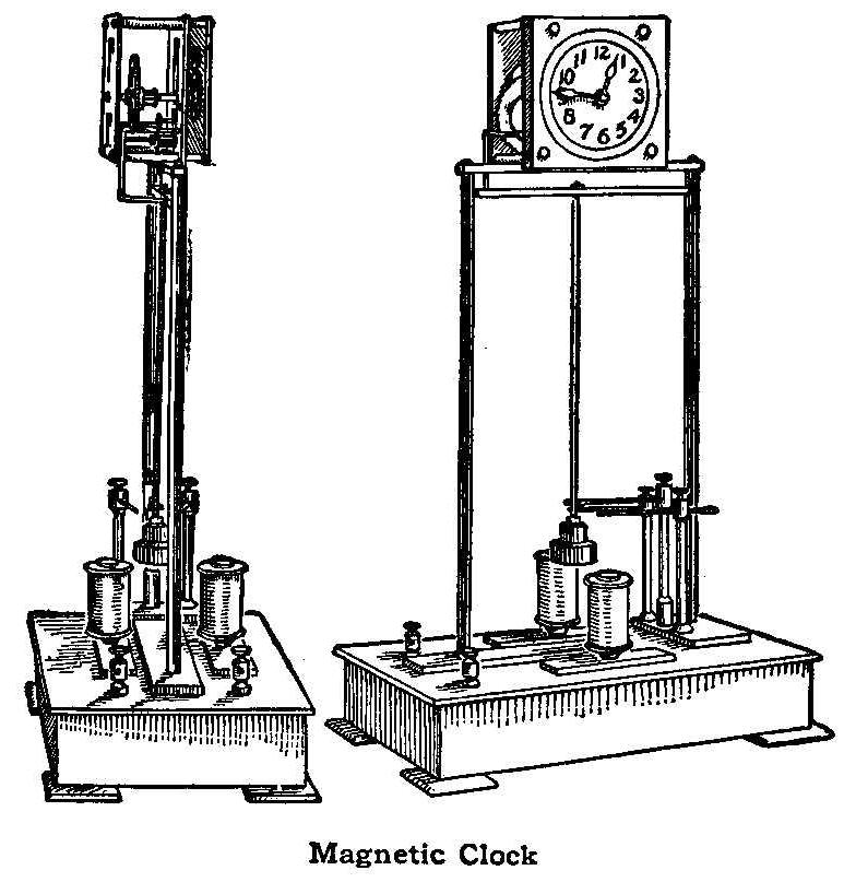
Magnetic Clock
The clock illustrated herewith is driven by means of
electromagnets acting directly on the pendulum bob. Unlike most
clocks, the pendulum swings forward and backward instead of
laterally. The construction is very simple, and the result is not
only novel but well worth while, because one does not have to
bother about winding a clock, such as this one, says the
Scientific American.
The clock is mounted on a wooden base measuring 3-3/4 by 6-1/2
in., by 1-5/16 in. thick. Secured centrally on this base is a 1/8
by 3/4-in. bar, 6 in. long and at each side of this, 5/16 in.
away, is an electromagnet, 3/4 in. in diameter and 1-7/16 in.
high. Two uprights, 7-1/2 in. high and 1/4 in. in diameter, are
secured in the base bar, and are connected at the top by a brass
yoke piece on which the clock frame is supported. Just below the
yoke piece a hole is drilled in each upright to receive the pivot
pins of the crosspiece secured to the upper end of the pendulum
rod. The pendulum bob at the lower end is adjusted to swing just
clear of the electromagnets. Mounted at the right-hand side of
the base are three tall binding-posts, the center one being 2-3/4
in. high, and the other two 2-5/8 in. high. Each is fitted with a
piece of copper wire provided with a small brass spring tip.
These springs lie in the plane of the pendulum, which serves to
swing the central tip first against one and then against the
other of the side tips, thereby closing the circuit of first one
magnet and then the other. Each magnet attracts the pendulum
until its circuit is broken by release of the center tip, and on
the return swing of the pendulum the circuit of the other magnet
is similarly closed. Thus the pendulum is kept in motion by the
alternate magnetic impulses. The clock train is taken from a
standard clock and the motion of the pendulum is imparted to the
escape wheel by means of a pawl, bearing on the latter, which is
lifted at each forward stroke of the pendulum by an arm
projecting forward from the pivotal end of the pendulum rod.
Method of Joining Boards
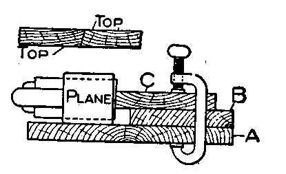
The amateur wood-worker often has trouble in joining two boards
together so that they will fit square and tight. The accompanying
sketch shows a simple and effective method of doing this. Secure
a board, A, about 12 in. wide that is perfectly flat. Fasten
another board, B, about 6 in. wide, to the first one with screws
or glue. Now place the board to be joined, C, on the board B,
letting it extend over the inside edge about 1 in. and fastening
it to the others with clamps at each end. Lay the plane on its
side and plane the edge straight. Place the second board in the
clamps in the same manner as the first, only have the opposite
side up. If the cutting edge of the blade is not vertical, the
boards planed in this manner will fit as shown in the upper
sketch. In using this method, first-class joints can be made
without much trouble.
Contributed by V. Metzech, Chicago.
Toy Gun for Throwing Cardboard Squares
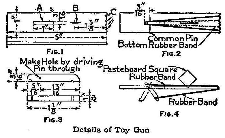
Details of Toy Gun
The parts of the gun are attached to a thin piece of wood 1 in.
wide and 5 in. long. It is best to use a piece of wood cut from
the side or cover of a cigar box. A rectangular hole 3/16 in.
wide and 1 in. long is cut in the wood longitudinally along its
axis and 1-3/8 in. from one end, as shown at A, Fig. 1. A small
notch is made with the point of a knife blade at B and notches
are cut in the end of the wood as shown at C. Rubber bands are
fastened in these notches as shown in Fig. 2. The trigger, whose
dimensions are given in Fig. 3, is fastened in the hole A, Fig.
1, by driving a pin through the wood. The assembled parts are
shown in Fig. 4. Place the cardboard square in the nick B, attach
the rubber bands and pull the trigger. The top rubber band will
fly off and drive the cardboard square 75 ft. or more. The
cardboard should be about 1/2 in. square. These can be cut from
any old pasteboard box.
Contributed by Elmer A. Vanderslice, Phoenixville, Pa.
Photographic Developing Tray
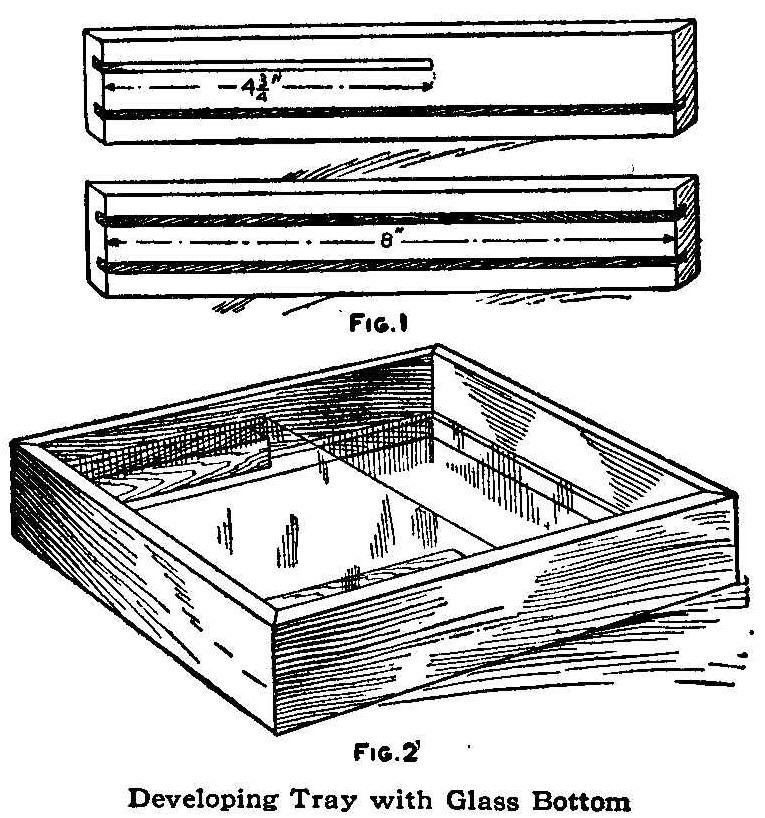
Developing Tray with Glass Bottom
Plates developed in an ordinary tray must be removed from the
bath occasionally for examination. The film when in a
chemical-soaked condition is easily damaged. The tray illustrated
herewith was made for the purpose of developing plates without
having to take hold of them until the bath had completed its
work, the examination being made through the plate and the bottom
of the tray.
A pocket is provided for the liquid developer in one end of the
tray when it is turned up in a vertical position. A tray for
developing 5 by 7-in. plates should be made 8 in. square inside.
The side pieces with the grooves for the glass are shown in Fig.
1. Two of each of these pieces are made with mitered ends. The
short groove shown in the top piece of the illustration is for
inserting the plate covering on the pocket end of the tray.
Two blocks, one-half the length of the side pieces, are put in
between the glass plates to hold the plate being developed from
dropping down when the tray is tipped up in a vertical position.
The glass bottom of the tray is 8-1/2 in. square, which allows
1/4 in. on all edges to set in the grooves of the side pieces.
The wood pieces should be well soaked in hot paraffin, and the
mitered corners well glued and nailed.
Contributed by J.A. Simonis, Fostoria, Ohio.
Iron Putty
A good filler used as a putty on iron castings may be made as
follows: Take, by weight, 3 parts of stiff keg
lead, 5 parts of
black filler, 2 parts of whiting, 5 parts of pulverized silica
and make into a paste with a mixture of one part each of coach
japan, rubbing varnish and turpentine.
Rubber Bands in Kite Balancing Strings
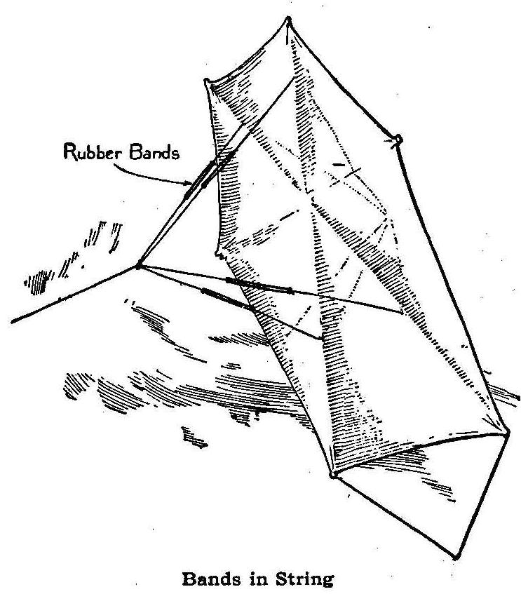
Bands in String
Kite flyers will find it to their advantage to place rubber bands
of suitable size in the balancing strings to the kite, as shown
in the illustration. This will prevent a “break-away” and also
make the right pull, if only two bands are put in the lower
strings.
Contributed by Thos. DeLoof, Grand Rapids, Michigan.
An Aid in Sketching
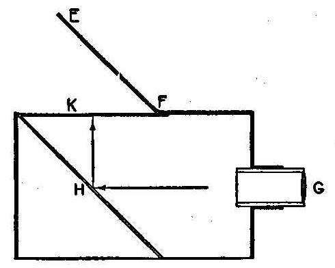
Sketching requires some little training, but with the apparatus
here illustrated an inexperienced person can obtain excellent
results. The apparatus is made of a box 8 in. deep, 8 in. wide
and about 1 ft. long. A double convex lens, G, is fitted in a
brass tube which should have a sliding fit in another shorter and
larger tube fastened to the end of the box. A mirror, II, is set
at an angle of 45 deg. in the opposite end of the box. This
reflects the rays of light passing through the lens to the
surface K, which may be either of ground or plain glass. The lid
or cover EF protects the glass and keeps the strong light out
when sketching. The inside of the box and brass tube are painted
a dull black.
In use, the device is set with the lens tube directed toward the
scene to be painted or sketched and the lens focused so the
reflected picture will be seen in sharp detail on the glass.
Select your colors and put them on the respective colors depicted
on the glass. If you wish to make a pencil drawing, all you have
to do is to fill in the lines in the picture on the ground glass.
If a plain glass is used, place tracing paper on its surface, and
the picture can be drawn as described.
How to Make Miniature Electric Lamp Sockets
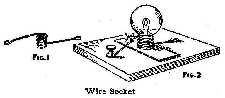
Wire Socket
A socket for a miniature lamp can be made as shown in the sketch.
A brass spring wire is wound around the base of the threads on
the lamp and an eye turned on each end to receive a screw and a
binding-post, as shown in Fig. 1. A piece of metal, preferably
copper, is attached to a wood base as shown in Fig. 2 and the
coil-spring socket fastened across it in the opposite direction.
Bend the wire so that the spring presses the lamp against the
metal. If the wire fits the lamp loosely, remove the lamp and
press the sides of the coil closer together. The metal parts can
be attached to any smooth surface of wood without making a
regular base.
Contributed by Abner B. Shaw, No. Dartmouth, Mass.
Imitation Arms and Armor-Part V
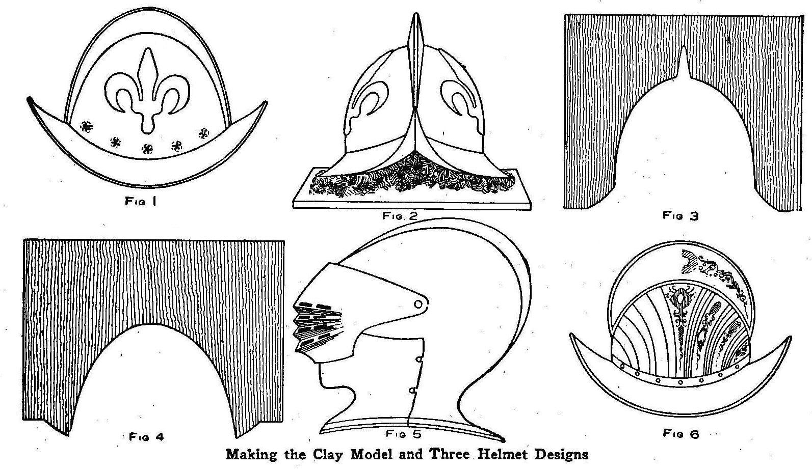
Making the Clay Model and Three. Helmet Designs
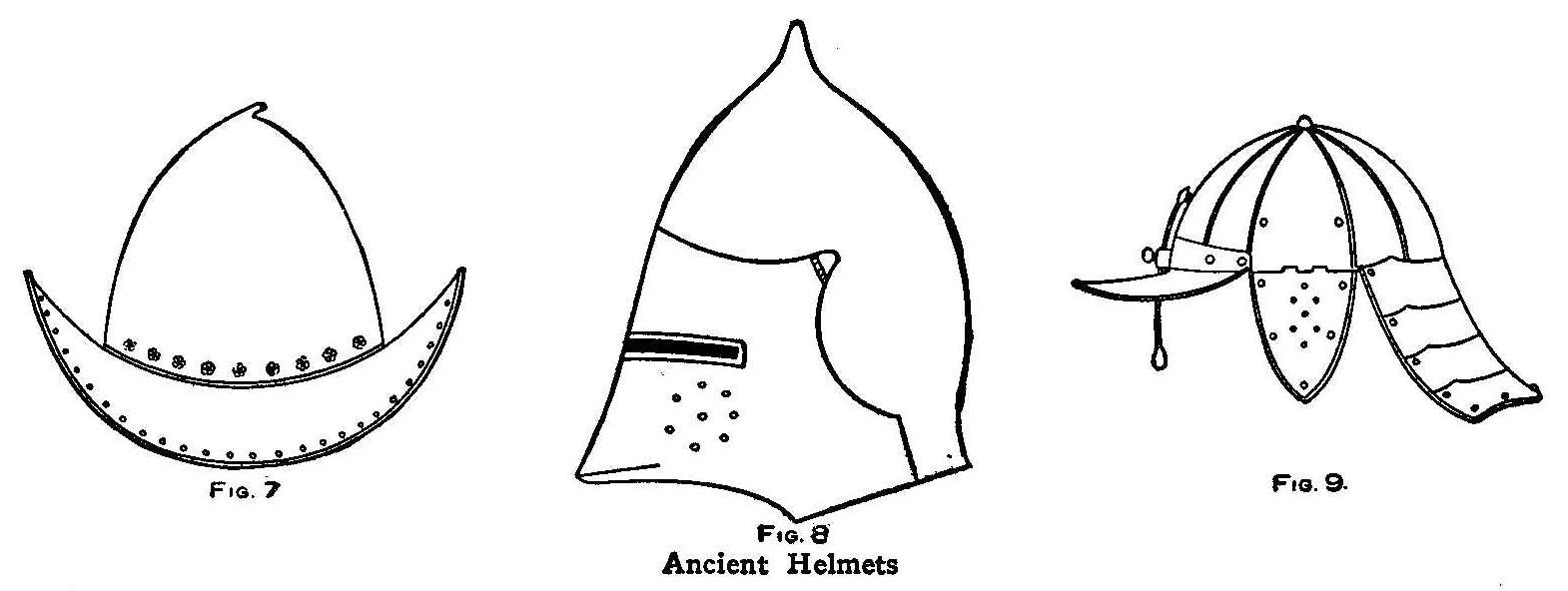
Ancient Helmets
The preceding chapters gave descriptions of making arms in
imitation of ancient weapons, and now the amateur armorer must
have some helmets to add to his collection. There is no limit to
the size of the helmet, and it may be made as a model or full
sized. In constructing helmets, a mass of clay of any kind that
is easily workable and fairly stiff, is necessary, says the
English Mechanic, London. It must be kept moist and well kneaded.
A large board or several planks, joined closely together, on
which to place the clay, will be necessary. The size of this
board will depend on the size of the work that is intended to be
modeled upon it.
The way to make a helmet is described in the following method of
producing a German morion, shown in Fig. 1. This helmet has
fleur-de-lis in embossed work, and on each side is a badge of
the civic regiment of the city of Munich. The side view of the
helmet is shown in Fig. 1.
The clay, is put on the board and modeled into the shape shown in
Fig. 2. This is done with the aid of a pair of compasses, a few
clay-modeling tools, and the deft use of the fingers. The
fleur-de-lis are slightly raised, as in bas-relief. To aid in
getting the helmet in correct proportion on both sides, and over
the crest on top, cut out the shape from a piece of wood, as
shown in Fig. 3, with a keyhole saw. This wood being passed
carefully and firmly over the clay will bring it into shape, and
will also show where there may be any deficiencies in the
modeling, which can then be easily remedied by adding more clay.
The cut-out pattern shown in Fig. 4 is the side outline of the
helmet.
Scraps of thin, brown, wrapping paper are put to soak in a basin
of water to which has been added about a tablespoonful of size
melted and well stirred, or some thin glue, and left over night
to soak. The paper should be torn in irregular shapes about as
large as the palm of the hand. After the clay model is finished,
give it a thin coat of oil-sweet or olive oil will answer the
purpose very well. All being ready, the clay model oiled, and the
basin of soaked paper near to hand, take, up one piece of paper
at a time and very carefully place it upon the model, pressing it
well on the clay and into and around any crevices and patterns,
and continue until the clay is completely covered.
This being done, give the paper a thin and even coating of glue,
which must be quite hot and put on as quickly as possible. Put on
a second layer of paper as carefully as before, then another
coating of glue, and so on, until there are from four to six
coats of glue and paper. When dry, the paper coating should be
quite stout and strong enough for the helmet to be used for
ornamental purposes. Before taking it off the model, which should
be no difficult matter, owing to the clay being oiled, trim off
any ragged edges of paper with a sharp knife, and smooth and
finish all over with some fine sandpaper. The paper is then given
a thin coat of glue and sections of tinfoil stuck on to give it a
finished appearance. When the helmet is off the model, make holes
with a small awl at equal distances, through which to insert some
fancy brass nails, bending the points over and flat against the
inside of the helmet.
A vizor helmet is shown in Fig. 5. This helmet has a movable
vizor in the front that can be lifted up, a crest on top, and
around the neck a narrow gorget which rests upon the wearer’s
shoulders. The whole helmet, with the exception of the vizor,
should be modeled and made in one piece. The vizor can then be
made and put in place with a brass-headed nail on each side. The
oblong slits in front of the vizor must be carefully marked out
with a pencil and cut through with a knife or chisel.
In Fig. 6 is shown an Italian casque of a foot soldier of the
sixteenth century. This helmet may have the appearance of being
richly engraved as shown in one-half of the drawing, or, a few
lines running down, as seen in the other part of the sketch, will
make it look neat. The band is decorated with brass studs.
An Italian cabasset of the sixteenth century is shown in Fig. 7.
This helmet is elaborately decorated with fancy and round-headed
nails, as shown: in the design.
In Fig. 8 is shown a large bassinet with a hinged vizor which
comes very much forward, so as to allow the wearer to breathe
freely. This helmet was worn about the sixteenth century, and was
probably used for tilting and tournaments.
A burgonet skull-cap of the seventeenth century is shown in Fig.
9. The vizor is composed of a single bar of metal, square in
shape, which slides up and down in an iron socket attached to the
front of the helmet, and is held in any position by a thumbscrew
as shown in the illustration.
A hole in the peak of the helmet allows it to hang in front of
the wearer’s face. This contrivance should be made of wood, the
helmet to be modeled in three pieces, the skullcap, peak and
lobster shell neck guard in one piece, and the ear guards in two
pieces, one for each side. The center of the ear guards are
perforated. All of the helmets are made in the same manner as
described for Fig. 1. They are all covered with tinfoil.
How to Repair Linoleum
A deep crack or fissure right in front of the kitchen cabinet
spoiled the appearance of the new linoleum. The damaged spot was
removed with a sharp knife and from a left-over scrap a piece was
cut of the same outline and size. The edges were varnished and
then the patch was set in the open space. The linoleum was given
a good coat of varnish making it more durable. When perfectly
dry, the piecing could not be detected.
Contributed by Paul Keller, Indianapolis, Indiana.
How to Make an Electric Stove
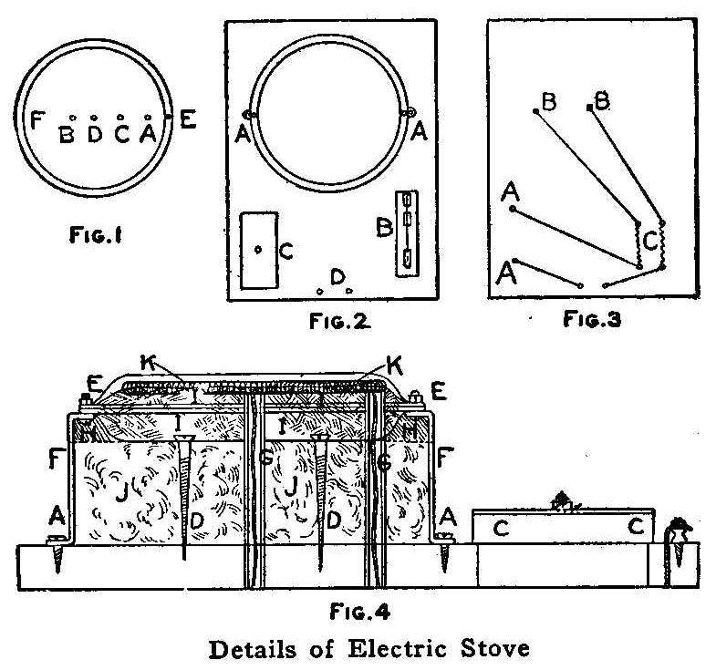
Details of Electric Stove
The parts necessary for making an electric stove are: Two metal
pie plates of the same size; 4 lb. of fire clay; two ordinary
binding posts; about 1 lb. of mineral wool, or, if this cannot be
obtained, thick sheet asbestos;
one oblong piece of wood, 1 in.
thick, 12 in. wide and 15 in. long; one small switch; one fuse
block; about 80 ft. of No. 22 gauge resistance wire,
German-silver wire is better, as it stands a higher temperature;
two middle-sized stove bolts with nuts; one glass tube, about
1/4 in. in diameter and 9 in. long, which can be bought from a
local druggist, and two large 3-in. screws.
If a neat appearance is desired, the wood can be thoroughly
sandpapered on one side and the corners and edges rounded off on
the upper side. Punch holes in one of the pie plates, as shown in
Fig. 1. The two holes, E and F, are on the rim and should be
exactly on a line with the hole D punched in the center. The
holes B and C are about 3 in. apart and should be at equal
distances from the center hole D. The rim of the second plate is
drilled to make two holes, AA, Fig. 2, that will match the holes
E and F in the first plate, Fig. 1. A round collar of galvanized
iron, FF, Fig. 4, 3 in. high, is made with a diameter to receive
the first plate snugly. Two small flaps are cut and turned out
and holes punched in their centers, AA, to receive screws for
holding it to the base. Two bolts are soldered in the holes E and
F, Fig. 1, and used to hold the rims of both plates together,
when they are placed in opposite positions, as shown in Fig. 4.
This will make an open space between the plates. The collar is
then screwed to one end of the base, as shown in Fig. 2.
Two holes are bored through the base to correspond with the holes
D and A in the bottom plate. The glass tube is cut to make two
pieces, each 4-1/2 in. long. This can be done easily by filing a
nick in the tube at the proper point and breaking it. These tubes
are forced into the holes bored in the base, and, if the
measurements are correct, should extend about 1/4 in. above the
collar. The mineral wool, JJ, Fig. 4, is then packed down inside
the collar, until it is within 1 in. of the top. This will allow
the plate, Fig. 1, to rest on the wool and the ends of the glass
tubes, GG, Fig. 4, to project through the holes D and A of the
plate, Fig. 1. The rim of the plate should be level with the top
edge of the collar. If asbestos
is used, the sheets should be cut
into disks having the same diameter as the inside of the collar,
and holes cut to coincide with the holes D and A of the plate.
The small scraps should be dampened and made into pulp to fill
the space H, Fig. 4. The plate, Fig. 1, is held to the base by
two screws which are run through the holes BC and take the
position shown by DD, Fig. 4.
The two binding-posts are attached on the base at D, Fig. 2, also
the switch B and the fuse block C, holes being bored in the base
to make the wire connections. The reverse side of the base, with
slits cut for the wires, is shown in Fig. 3. The points marked BB
are the glass tubes; AA, the holes leading to the switch; and C,
the fuse block. The wires run through the glass tubes GG, Fig. 4,
are allowed to project about 1 in. for connections. The best way
to find the correct length of the resistance wire is to take a
large clay or drain tile and wind the wire tightly around it,
allowing a space between each turn. The tile is then set on its
side with a block or brick under each end. It should not be set
on end, as the turns of the wires, when heated, will slip and
come in contact with each other, causing a short circuit. When
the tile is in place, a short piece of fuse wire is fastened to
each of its two ends. A 5-ampere fuse wire is about strong
enough. A connection is made to these two wires from an
electric-light socket. The wire will get hot but probably remain
the same color. If this is the case, one of the feed wires is
disconnected from the fuse wire and gradually moved farther down
the coil until a point is found where the resistance wire glows a
dull red. This point marks the proper length to cut it, as the
wire should not be allowed to become any hotter. If the wire gets
bright hot when the current is turned on, more wire should be
added. The wire is then made into a long coil by winding it
around a large wire nail. The coils should be open and about 1/8
in. apart.
Next, the fire clay is moistened and well mixed, using care not
to get it too wet. It should have the proper consistency to mould
well. The clay, II, Fig. 4, is then packed in the first plate to
a height of about 1/4 in. above the rim. While the clay is damp,
one end of the coil is connected with the wire in the central
glass tube, and the coil laid in a spiral winding on the damp
clay, KK, and pressed into it. When this is done, the other end
is connected to the wire projecting from the outer glass tube. As
these connections cannot be soldered, the ends of the wires
should be twisted closely together, so that the circuit will not
become broken. Make sure that the coils of wire do not touch each
other or the top plate. The fuse wire (about 5 amperes) is put
into the fuse block, and wires with a socket adapter connected to
the two binding-posts. The top plate is put in place and screwed
down. This completes the stove.
It should be set aside in a warm place for a few days to dry out
the packing. If it is not thoroughly dry, steam will form when
the current is applied. It should not be left heated in this
condition. The top plate is used when cooking and removed when
making toast.
Contributed by R. H. Cnonyn, St. Catherines, Can.
How to Make Weights for Athletes
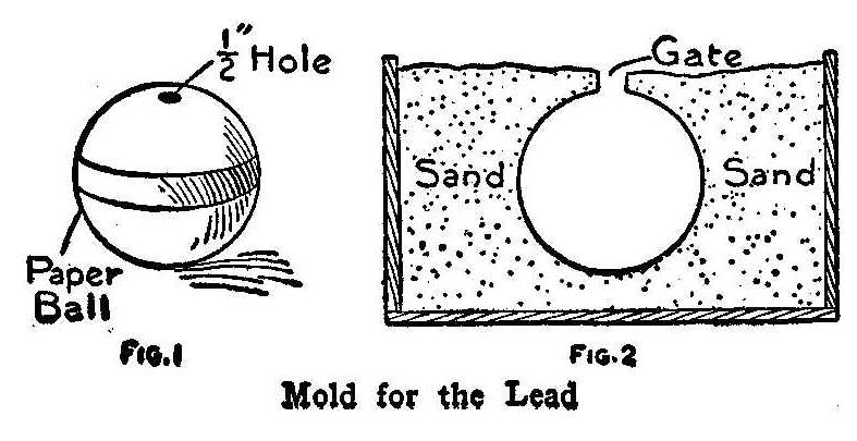
Mold for the Lead
Many times boys would like to make their own shots and weights
for athletic stunts, but do not know how to go about it to cast
the metal. In making a lead
sphere as shown in the illustration,
it is not necessary to know the method of molding.
The round lead
weight for shot-putting or hammer throwing can be cast in a
hollow cardboard or pressed-paper ball, sold in department and
toy stores for 10 cents. Cut a 1/2-in. hole in the ball as shown
in Fig. 1 and place it with the hole up in damp sand and press or
tamp the sand lightly around the ball as shown in the section,
Fig. 2. Cover over about 1 in. deep. A wood plug inserted in the
hole will prevent any sand falling inside. When the sand is
tamped in and the plug removed, it leaves a gate for the metal.
Pour melted lead
into the gate until it is full, then, when cool,
shake it out from the sand and remove the charred paper. A file
can be used to remove any rough places. The dry paper ball
prevents any sputtering of the hot lead.
Contributed by W. A. Jaquythe, Richmond, Cal.
Removing Pies from Pans
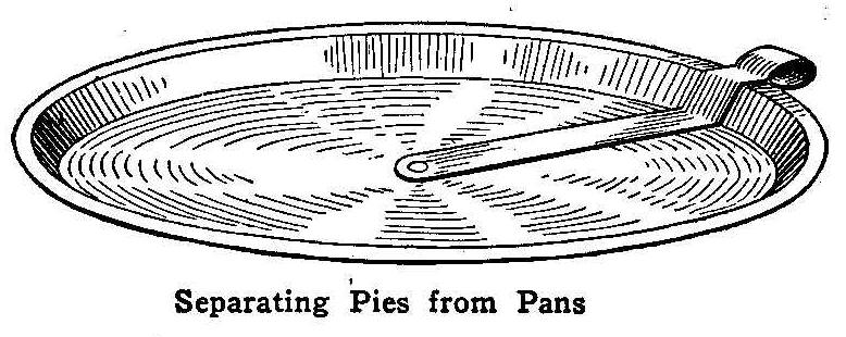
Separating Pies from Pans
Sometimes the juices from a hot pie make it stick to the pan so
tightly that a knife blade must be run under to cut it loose. If
a knife with a flexible blade is not used, the pie will be
damaged. If the pie pans are provided with the simple attachment
shown in the accompanying sketch, the baked dough can be
separated from the tin with one revolution of the cutter. The
cutter is made from a piece of heavy tin, bent to the same
outline as the inside of the pan and pivoted at its center.
Stretcher for Drying Photograph Prints
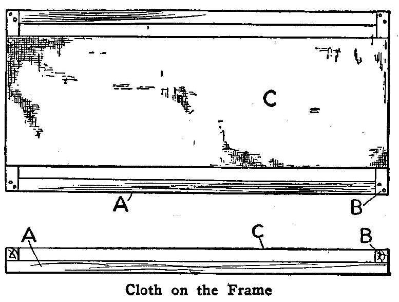
Cloth on the Frame
A quick and convenient way to dry prints is to place them on a
cheesecloth stretcher. Such a stretcher can be made on a light
wood frame, constructed of 3/4-in. square material in any size,
but 12 by 24 in. is large enough. The end pieces B are fastened
on top of the long side pieces A, and the cheesecloth C stretched
and tacked over them, as shown.
The prints should be placed face up on the cloth, and the frame
set near a window. If the stretcher is made in this way, the air
can enter from both top and bottom, and the prints will dry
rapidly. Several of these frames can be stacked and a large
number of prints thus dried at the same time.
Contributed by Andrew G. Thorne, Louisville, Ky.
A Temporary Funnel
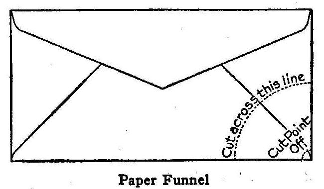
Paper Funnel
The amateur photographer often has some solution which he desires
to put into a bottle which his glass funnel will not fit, says
the Photographic Times. The funnel made by rolling up a piece of
paper usually allows half of the solution to run down the outside
of the bottle, thereby causing the amateur to be dubbed a
“musser,” A better way is to take an ordinary envelope and cut it
off as shown by the dotted lines. Then clip a little off the
point, open out, and you have a funnel that will not give any
trouble. It is cheap and you can afford to throw it away when
dirty, thereby saving time and washing.
An Electric Engine
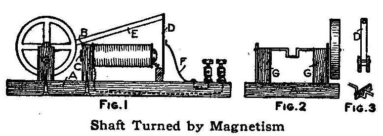
Shaft Turned by Magnetism
The parts of this engine are supported on a base 3/4 in. thick, 4
in. wide and 7 in. long. The upright B, Fig. 1, which is 1/2 in.
thick and 3 in. high, is secured across the base about one-third
of the distance from one end and fastened with a wood screw put
through from the under side. The magnet core C is made of a
carriage bolt, 2-1/2 in. long, which is fastened in a hole in the
top part of the upright B so that the end C will protrude
slightly. Before placing the bolt in the hole of the upright,
slip on two cardboard washers, each 1 in. in diameter, one at the
head end and the other against the upright B. Wrap a thin piece
of paper around the bolt between the washers and wind the space
full of No. 22 gauge magnet wire, allowing each end to project
for connections.
The driving arm D, Figs. 1 and 3, is made of a piece of soft
sheet iron, 1/2 in. wide and 3 in. long. A small block is
fastened to the lower end of the metal and pivoted between two
uprights, 1/2 in. high, which are fastened to the base. The
uprights on each side of the block are better shown in Fig. 3.
Two supports, each 1/2 in. thick and 3 in. high, are fastened
with screws about half way between the end of the base and the
upright B, Fig. 1. The end view of these supports is shown in
Fig. 2, at GG. A 1/8-in. hole is bored through the top part of
each support so they will be in a line for the axle. The axle is
made of a piece of steel 1/8 in. in diameter and about 4 in.
long. An offset is bent in the center, as shown, for the crank. A
small flywheel is attached to one end of the shaft. The
connecting rod E, Fig. 1, is made of wood and fastened to the
upper end of the driving arm D with a small screw or nail. The
contact F is made of a strip of copper, 1/4 in. wide. This is to
open and close the circuit when the engine is running. The
connections are made as shown in Fig. 1.
Connect two dry cells to the binding-posts and turn the flywheel.
The current passing through the magnet pulls the driving arm
toward the bolt head, which gives the shaft a half turn. The
turning of the shaft pulls the arm away from the copper piece F,
causing a break in the current. As the shaft revolves, the arm is
again brought back against the copper strip F, thus the current
is broken and applied at each revolution of the shaft.
Contributed by S. W. Herron, Le Mars, Iowa.
Child’s Home-Made Swing Seat
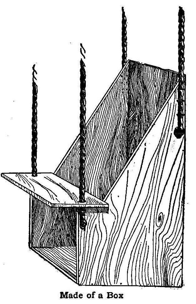
Made of a Box
A very useful swing or seat for children can be made from a box
or packing case. Procure a box of the right size and saw it out
in the shape shown in the illustration. The apron or board in
front slides on the two front ropes. The board can be raised to
place the child in the box and to remove him. The ropes are
fastened to the box by tying knots in their ends and driving
staples over them.
Clay Flower Pots Used for Bird Houses
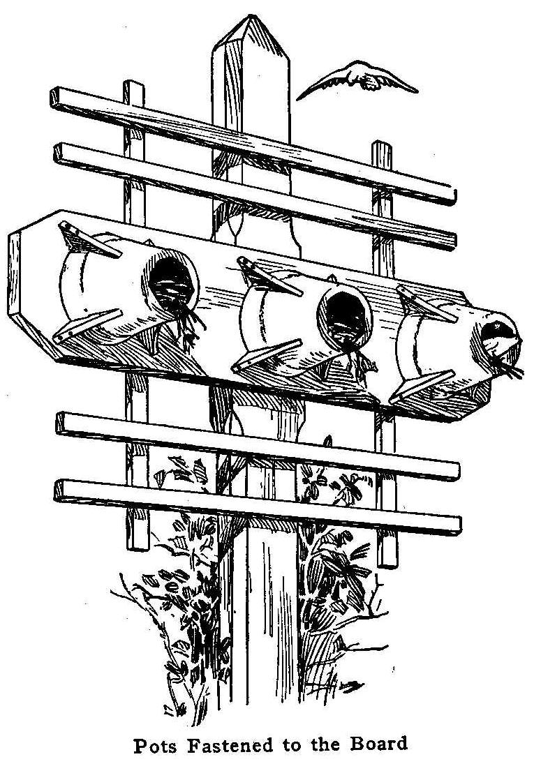
Pots Fastened to the Board
A novel use of the common garden flower pot may be made by
enlarging the small opening at the bottom with a pair of pliers,
and carefully breaking the clay away until the opening is large
enough to admit a small bird.
Place the pot, bottom side up, on a board, 3 in. wider than the
diameter of the largest pot used, and fasten it to the board with
wood cleats and brass screws. Fit the cleats as close as possible
to the sides of the pot. One or more pots may be used, as shown
in the sketch.
The board on which the pots are fastened is nailed or screwed to
a post or pole 10 or 12 ft. in height. The board is braced with
lath or similar strips of wood, making a framework suitable for a
roost. In designing the roost, the lath can be arranged to make
it quite attractive, or the braces may be of twigs and branches
of a tree to make a rustic effect.
Contributed by William F. Stecher, Dorchester, Mass.
Location of a Gas Meter
The gas meter should not be located in a warm place or the gas
will expand before the meter measures it and the gas bill will be
proportionately increased. Gas expands by about 1/491 part of its
volume for each deg. F. that it is heated. If the meter is warmed
10 deg. F., it will make the gas cost over 2 per cent more,
without any corresponding benefit.
How to Make Rope Grills
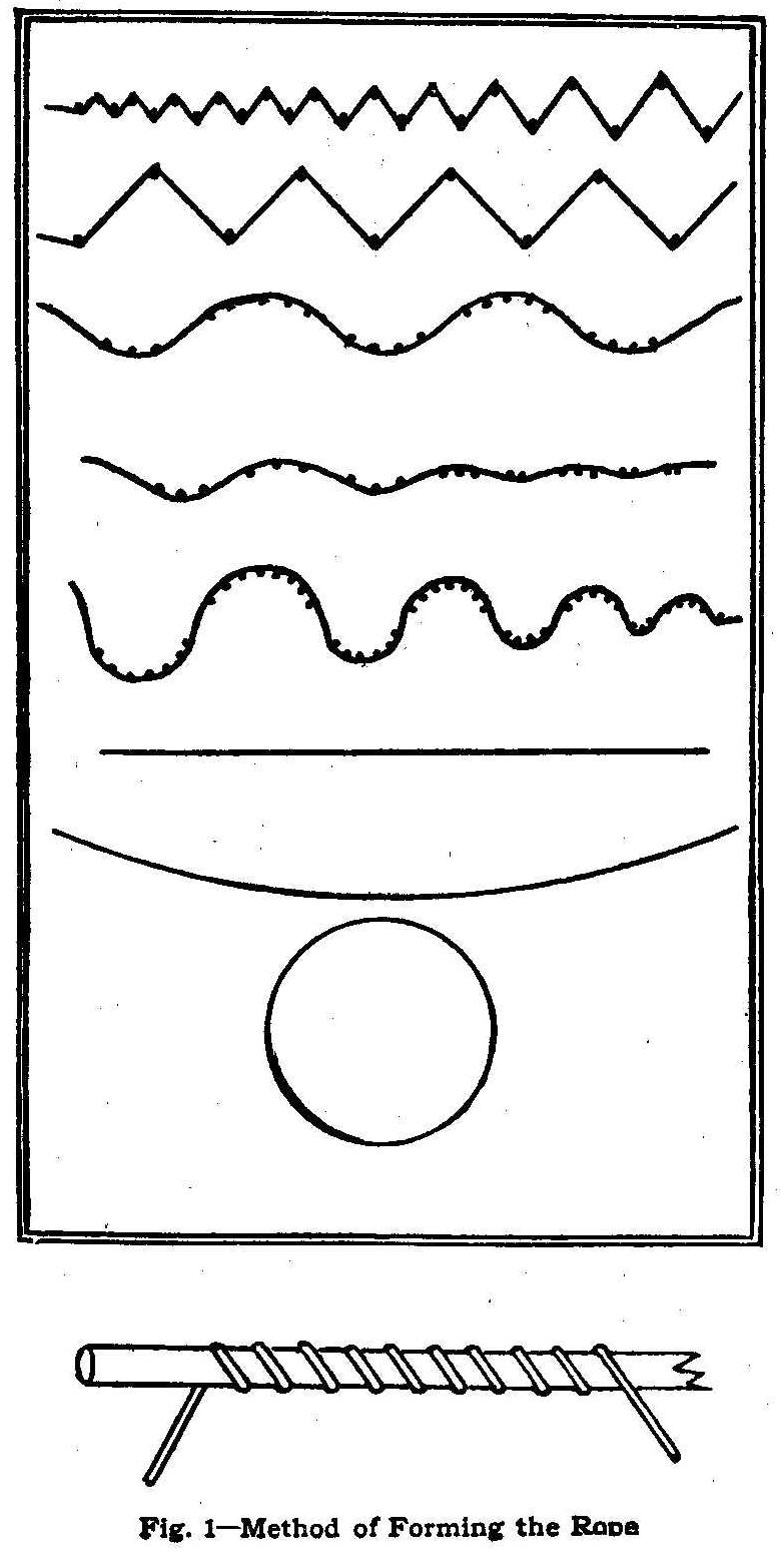
Fig. 2-Designs for Grills
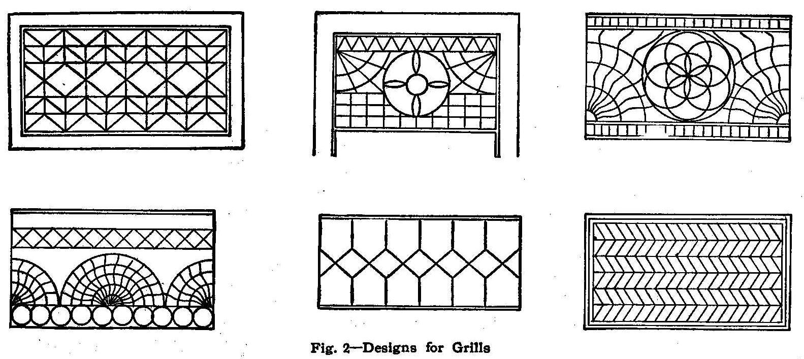
Fig. 1—Method of Forming the Rope
Beautiful and useful household ornaments, grills and gratings for
doors, windows, shelves, odd corners, etc., can be made by the
following method at a slight cost and by anyone possessing a
little ingenuity. The materials required are rope or, preferably,
common window cord (called sash cord) about 5/16 in. in diameter;
ordinary glue, paraffin and paint or varnish. A few strips of
wood or molding are very handy to use around the edges.
The design must be considered first and when one is selected, if
it is other than straight lines, adopt the method described.
Take a smooth flat board and layout the design or designs which,
when combined, will produce the pattern desired. Drive finishing
nails at the angle points or along curves as required. Coat the
board along the lines of the patterns with melted paraffin, using
an ordinary painter’s brush to prevent the ropes from sticking to
the boards after they are soaked in glue and run around the
nails.
Soak the sash cord in common glue sizing for a short time, then
bend or twist it along or around the lines desired, as shown in
Fig. 1, and give it time to dry. The bottom part of the sketch,
Fig. 1, shows a method of winding the rope on a round stick to
make circular objects. Wind the desired number of turns and when
dry, cut and glue them together.
In Fig. 2, six designs are shown. These suggest ideas in making
up combinations or in plain figures and the number is limited
only by the ingenuity of the designer.
Contributed by Geo. M. Harrer, Lockport, N. Y.
A Simple and Effective Filter
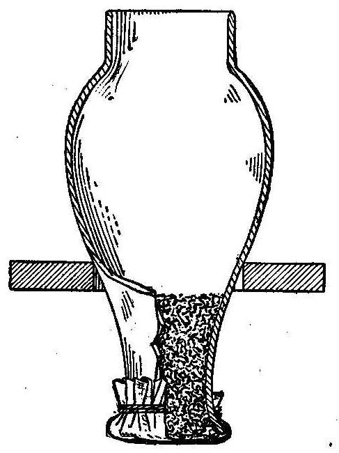
Procure an ordinary lamp chimney and fit two or three thicknesses
of cheese cloth over the end of it. Press a tuft of absorbent
cotton into the small part of the neck to a depth of about 3 in.
Insert the chimney in a hole cut in a wood shelf used as a
support. Pour the water in until the filter is filled, when it
will be observed that any organic matter, chips of iron rust,
etc., will be retained by the cotton. The fine organic matter may
penetrate the cotton for about 1 in., but no farther. The
resultant filtered water will be clear and pure.
Cutting Tools
The cutting point of a tool should never be below the centers.
Imitation Arms and Armor-Part VI
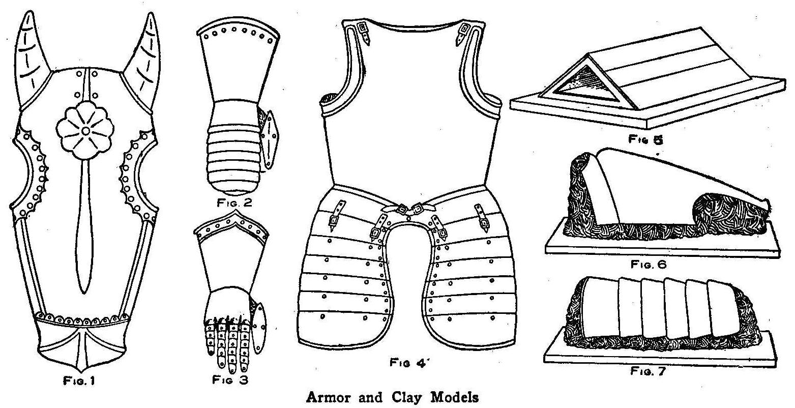
Armor and Clay Models
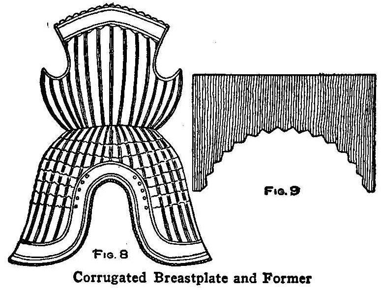
Corrugated Breastplate and Former
A mass of any kind of clay that is easily modeled and fairly
stiff must be prepared and kept moist and well kneaded for making
the models over which paper is formed to make the shape of the
articles illustrated in these sketches. A modeling board must be
made of one large board or several pieces joined closely together
upon which to work the clay, says the English Mechanic, London.
The size of the board depends upon the size of the work to be
made.
An open chamfron of the fifteenth century is shown in Fig. 1.
This piece of horse armor, which was used in front of a horse’s
head, makes a splendid center for a shield on which are fixed the
swords, etc., and is a good piece for the amateur armorer to try
his hand on in the way of modeling in clay or papier maché work.
The opening for the animal to put his head into is semicircular,
and the sides do not cover the jaws. As the main part of this
armor is worn in front of the head the extreme depth is about 4
in. The entire head piece must be modeled in clay with the hands,
after which it is covered with a thin and even coating of sweet
or pure olive oil. A day before making the clay model some pieces
of thin, brown wrapping paper are torn in irregular shapes to
the size of the palm of the hand and put to soak in a basin of
water in which a tablespoonful of size has been dissolved. If
size cannot be obtained from your local painter, a weak solution
of glue will do equally well. All being ready, and the clay model
oiled, take up one piece of paper at a time and very carefully
place it on the surface of the model, pressing it on well and
into and around any crevices and patterns. Continue this
operation until the clay model is completely covered on every
part. This being done, give the paper a thin and even coating of
glue, which must be quite hot and laid on as quickly as possible.
Lay on a second layer of paper as carefully as before, then
another coat of glue, and so on until there are five or six coats
of glue and paper. When this is dry it will be strong enough for
all ornamental purposes. The ragged edges of the paper are
trimmed off with a sharp knife and the whole surface smoothed
with fine sandpaper. Then carefully glue on sections of tinfoil
to give the armor the appearance of steel. The armor is now
removed from the model.
A mitten gauntlet of the fifteenth century is shown in Fig. 2.
This can be made in one piece, with the exception of the thumb
shield, which is separate. The thumb shield is attached to the
thumb of an old glove which is fastened with round headed nails
on the inside of the gauntlet. The part covering the wrist is a
circular piece, but the back is not necessary, as it would not be
seen when the gauntlet is hanging in its place.
In Fig. 3 is shown a gauntlet of the seventeenth century with
separately articulated fingers. This gauntlet may be molded in
one piece, except the thumb and fingers, which must be made
separately and fastened with the thumb shield to the leather
glove that is attached to the inside of the gauntlet, the same as
in Fig. 2.
A breastplate and tassets of the sixteenth century are shown in
Fig. 4. The tassets are separate and attached to the front plate
with straps and buckles, as shown in the sketch. There is a belt
around the waist which helps to hold the back plate on. Attached
to the back of the plate would be two short straps at the
shoulder. These are passed through the buckles shown at the top
right and left-hand corners of the front plate. For decorative
purposes the back plate need not be made, and therefore it is not
described. The method of making armor is the same as of making
helmets, but as larger pieces are formed it is well to use less
clay owing to the bulk and weight.
An arrangement is shown in Fig. 5 to reduce the amount of clay
used. This triangular-shaped support, which can be made in any
size, is placed on the modeling board or bench and covered with
clay. This will make the model light and easy to move around, and
will require less clay. It is not necessary to have smooth
boards; the rougher the better, as the surface will hold the
clay. The clay forms modeled up ready to receive the patches of
brown paper on the surface are shown in Figs. 6 and 7.
A German fluted armor used at the beginning of the sixteenth
century is shown in Fig. 8. The breastplate and tassets of this
armor are supposed to be in one piece, but for convenience in
making it will be found best to make them separately and then
glue them together after they are taken from the model. A narrow
leather belt placed around the armor will cover the joint. Fluted
armor takes its name from a series of corrugated grooves, 1/2 in.
in depth, running down the plate. A piece of board, cut into the
shape shown in Fig. 9, will be very useful for marking out the
fluted lines.
Home-Made Hand Vise
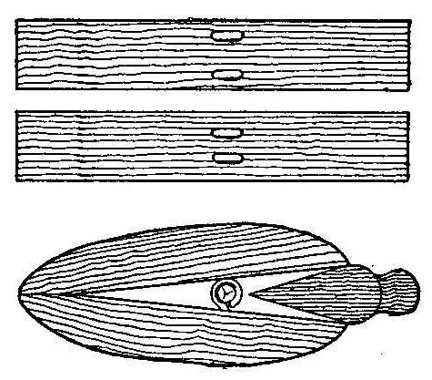
A vise for holding small articles while filing can be made as
shown in the illustration. The vise consists of three pieces of
wood, two for the jaws and one a wedge. The hinge for connecting
the two jaws is made of four small screw eyes, two in each jaw.
When locating the place for the screw eyes, place the two in one
jaw so they will fit between the two of the other jaw. Put a nail
through the eyes when the jaws are matched together and they are
ready for the wedge in clamping the article to be
filed.
Contributed by John G. Buxton, Redondo Beach, Calif.
Detector for Slight Electrical Charges
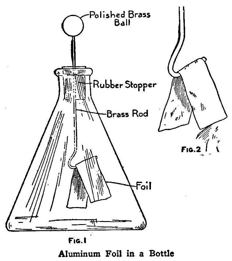
Aluminum Foil in a Bottle
A thin glass bottle is thoroughly cleaned and fitted with a
rubber stopper. A hole is made through the center of the stopper
large enough to admit a small brass rod. The length of this rod
will be governed by the shape of the bottle, but 3-1/2 in. will
be about right. The bottom of the rod is bent and two pieces of
aluminum foil, each about 1/4 in. wide and 1/2 in. long, are
glued to it. The two pieces of foil, fastened to the rod, are
better shown in Fig. 2. Fasten a polished brass ball to, the top
of the rod, and the instrument is ready for use. Place the
article which you wish to test near the ball, and if it holds a
slight electrical charge, the two pieces of foil will draw
together. If it does not hold a charge, the foils will not move.
Transcriber’s note: The foil pieces will move apart, not
together.
Contributed by Ralph L. La Rue, Goshen, N. Y.
Fishing through Ice with a Tip-Up
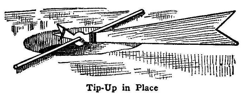
Tip-Up in Place
The tip-up, used for signaling the fisherman when a fish is
caught, is made of a 1/4-in. pine board, about 15 in. long,
2-1/2 in. wide at one end and narrowing down to about 1 in at the
other. At a point 6 in. from the smaller end, the board should be
cut slightly wider and a 1/2-in. hole bored through it. Two or
three wrappings of fine copper wire may be wound around the board
on each side of the hole to give added strength. Both ends of the
board should be notched deeply.
A long gash is cut in the ice and then a round hole is made with
a chisel, as this will cut under the water without splashing. The
chipped ice can be removed with a pail. A rod or round stick of
wood is passed through the hole in the tip-up and placed across
the round hole, as shown in the illustration.
The fishhook is baited in the usual way and hung on a line from
the short end of the tip-up. When a fish is hooked, the other
end will tip up and signal the fisherman. Any number of holes can
be cut in the ice and a tip-up used in each, thus enabling one
person to take care of as many lines.
Home-Made Candle Holder
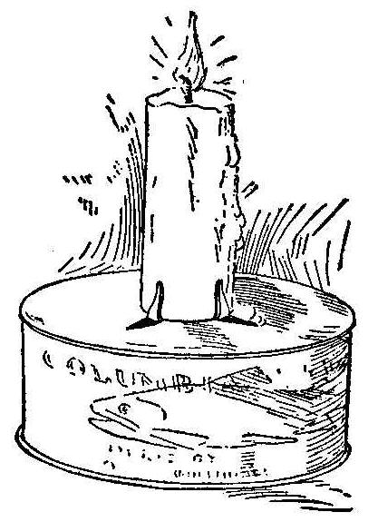
The candlestick or holder shown in the illustration is made of an
ordinary tin can, such as is used for canning salmon or potted
ham. Three triangular cuts are made in the cover or bottom of the
can and the points turned up about the candle. The can may be
bronzed, silvered, enameled or otherwise decorated, thus making
it ornamental as well as useful.
Contributed by Mrs. A. M. Bryan, Corsicana, Texas.
How to Make a Match Holder of Wood and Metal
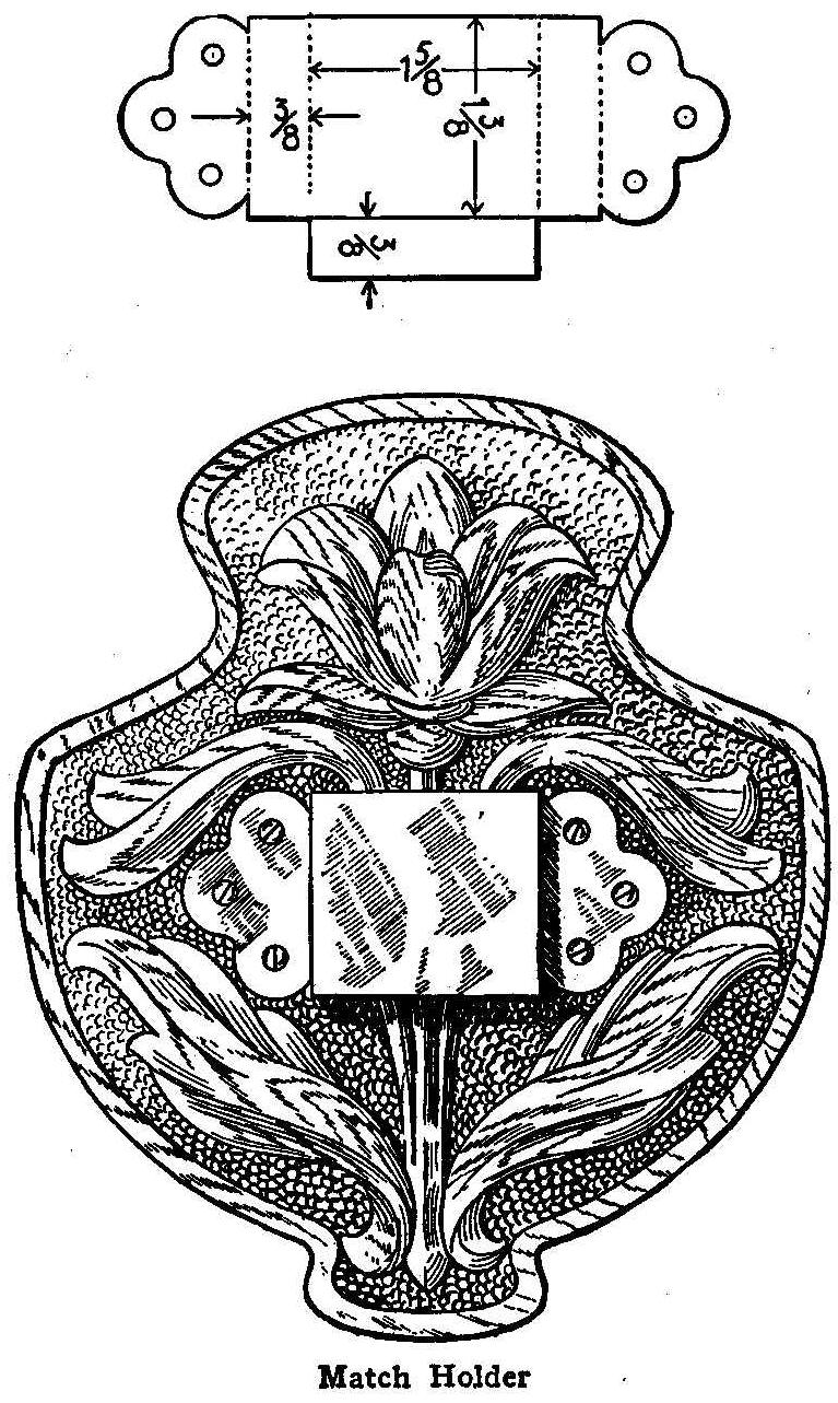
Match Holder
A very simple piece of art craft work is easily made, as follows:
Secure a piece of paper and upon it draw the outline and design,
as indicated in the accompanying sketch. The size may be made to
suit the taste of the worker. A good size is 5 in. wide by 6 in.
long over all. The metal holder should be proportioned to this
size, as shown.
Having completed the drawing, take a piece of thin wood, 3/8 or
1/4 in. thick, and trace upon it the design and outline, using a
piece of carbon paper. A couple of thumb tacks should be used to
fasten the paper and design in place. Put the tacks in the lines
of the design so that the holes will not show in the finished
piece. Any kind of wood will do. Basswood or butternut, or even
pine, will do as well as the more expensive woods.
Next prepare the metal holder. This may be made of brass or
copper and need not be of very heavy gauge-No. 22 is plenty heavy
enough. The easiest way to get the shape of the metal is to make
a paper pattern of the development. The illustration shows how
this will look and the size of the parts for the back dimensioned
above. Trace this shape on the metal with the carbon paper and
cut it out by means of metal shears. Polish the metal, using
powdered pumice and lye,
then with a nail, punch the holes,
through which small round-head brass screws are to be placed to
hold the metal to the wood back. Carefully bend the metal to
shape by placing it on the edge of a board and putting another
board on top and over the lower edge so as to keep the bending
true.
The wood back may be treated in quite a variety of ways. If soft
wood, such as basswood or pine was used, it may be treated by
burning with the pyrography outfit. If no outfit is at hand a
very satisfactory way is to take a knife and cut a very small
V-shaped groove around the design and border so as to keep the
colors from “running.” Next stain the leaves of the conventional
plant with a little green wood dye and with another dye stain the
petals of the flower red. Malachite and mahogany are the colors
to use. Rub a coat of weathered oil stain over the whole back and
wipe dry with a cloth. The green and red are barbarously
brilliant when first put on, but by covering them at the same
time the background is colored brown, they are “greyed” in a most
pleasing manner. When it has dried over night, put a coat or two
of wax and polish over the wood as the directions on the can
suggest.
The metal holder may next be fastened in place.
If one has some insight in carving, the background might be
lowered and the plant modeled, the whole being finished in
linseed oil. If carving is contemplated, hard woods such as
cherry or mahogany should be used.
Protecting the Fingers from Chemicals
The finger nails and fingers may be easily protected from stains
of chemicals by coating them with a wax made up as follows: Melt
white wax in the same manner as melting glue. This may be done by
cutting the wax into small pieces, placing them in a vessel and
setting the vessel in boiling water. To each ounce of melted wax
thoroughly stir in 1 dr. of pure olive oil. The fingers should
be dipped into the wax while it is in a liquid state. This will
form a coating that will permit the free use of the fingers, yet
protects the skin from the chemicals. It is useful for
photographers.
Combined Turning Rings and Swings
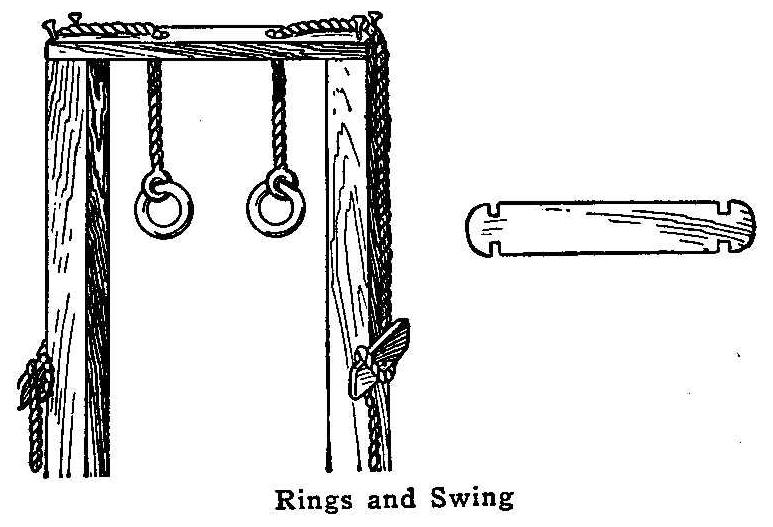
Rings and Swing
This trapeze, with rings for the large boys and a swing for the
smaller ones, can be made on the same standards. Instead of the
usual two short ropes, tied and bolted through the top
crosstimber bore two holes large enough for the ropes to pass
through easily. Pass the rope along the crosspiece and down the
post and tie it to cleats nailed at a height that can be easily
reached.
At the ends of the crosspiece drive two nails, allowing them to
project 1 or 2 in. This will keep the rope from slipping off when
the rings and swing are raised and lowered. All sharp edges
should be sandpapered to prevent the rope from being cut. A board
with notches cut in the ends will make a good swing board which
can be removed instantly.
Contributed by W. A. Jaquythe, Richmond, Cal.
Homemade Telegraph Key
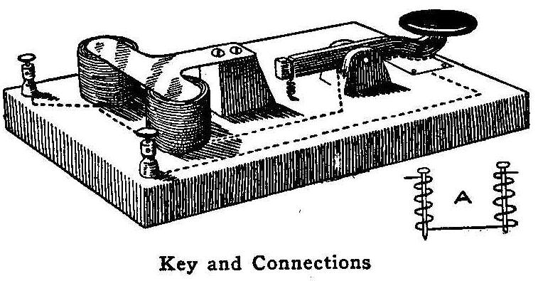
Key and Connections
A piece of wood, 1/2 in. thick, 2 in. wide and 5 in. long, is
used for the base of this instrument. Two wire nails, each 1 in.
long, are used for the cores of the magnets. Each nail is wound
with three or four layers of fine insulated magnet wire, about
No. 25 gauge, similar to that used in electric bells, leaving
about 1/4 in. of the end bare so that they may be driven into the
wood base. The connections for the coils are shown in the sketch,
at A.
About 1 in. behind the coils is fastened a small block of wood,
the top of which is just even with the top of the nails in the
coils. A piece of tin, cut in the shape of the letter T, is
fastened with two screws to the top of this block, and the end
bent slightly so as to clear the top of the nails about 1/32 in.
The key lever is cut from a thin piece of wood, in the shape
shown in the sketch, and pivoted in a slotted block which is used
as a base for the key. A piece of bare copper wire is fastened
along the under side of the key, as shown by the dotted lines. A
rubber band, passing over the end of the key and attached to the
base with a tack, acts as a spring to keep the key open. A small
piece of tin is fastened to the base under the knob of the key.
This is for making the contact between the copper on the key and
the wires from the coils, when the key is pushed down.
Contributed by W. H. Lynas.
Protecting Sleeves
Bicycle trousers-guards make excellent sleeve bands when the
cuffs are turned back and rolled above the elbows.
Imitation Arms and Armor—Part VII
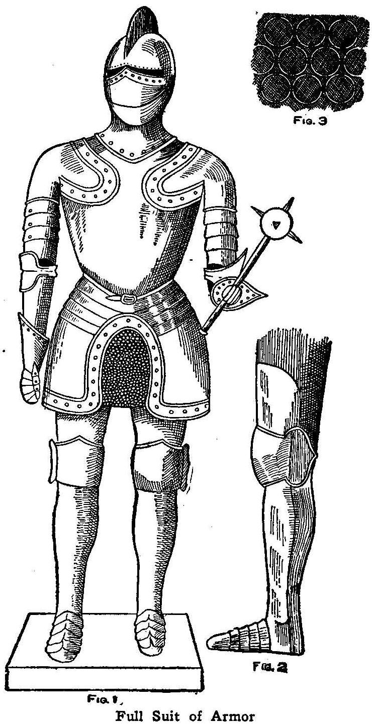
Full Suit of Armor
The helmets, breastplates and gauntlets described in parts V and
VI can be used in making up a complete model for a full suit of
armor of any size, as shown in Fig. 1. All of the parts for the
armor have been described, except that for the legs. Figure 2
shows how the armor is modeled on the side of the left leg. The
clay is modeled as described in previous chapters, the paper
covering put on, and the tinfoil applied in imitation of steel.
The chain mail seen between and behind the tassets is made by
sewing small steel rings on a piece of cloth as shown in Fig. 3.
These rings may be purchased at a hardware store or harness shop.
The whole figure when completed is placed on a square box covered
with red or green baize. The armor should be supported by a light
frame of wood built up on the inside, says the English Mechanic,
London. Two vertical pieces are firmly attached to the box so
they will extend up inside the legs, and at the top of them is
attached a crosspiece on which is placed a vertical stick high
enough to carry the helmet. The two lower pieces must be built up
and padded out with straw, then covered with red cloth or baize
to represent the legs.
In making up the various pieces for a full model it will be found
very convenient to use rope, a stout cord or strings in making up
the patterns on the parts. Instead of using brass headed nails,
brass paper fasteners will be found useful. These can be purchased
at a stationery store. Secure the kind having a round
brass head from which hang two brass tongues. These are pushed
through a hole and spread out flat on the opposite side. Other
materials can be used in the place of tinfoil to represent steel.
Silver paper will do very well, but if either the tinfoil or
silver paper are found difficult to manipulate, go over the armor
with a coat of silver paint put on with a brush. When dry give
the surface a coat of varnish.
A Home-Made Tripod Holder
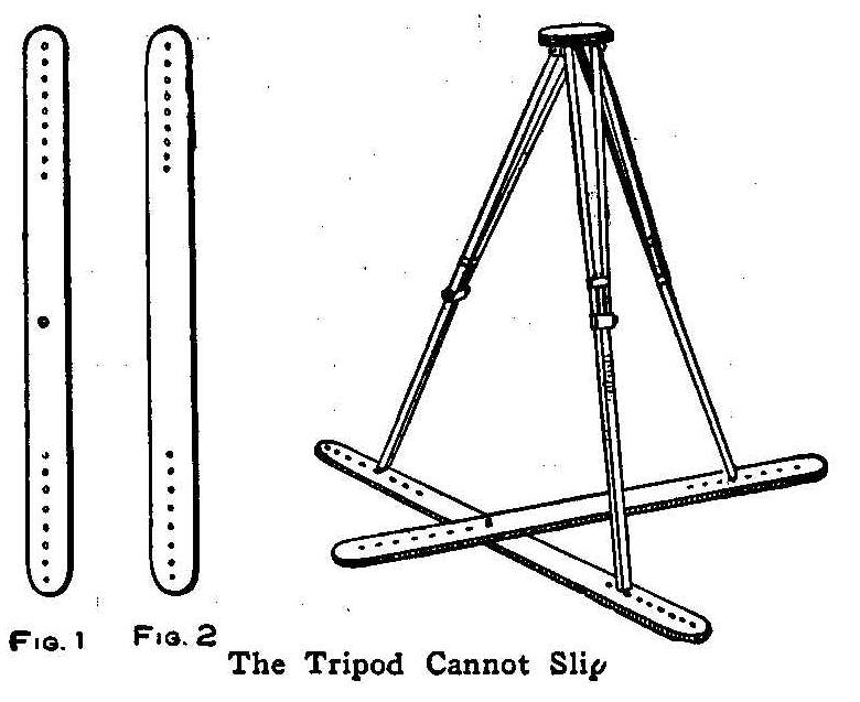
The Tripod Cannot Slip
An inexpensive tripod holder, one that will prevent the tripod
from slipping on a smooth floor, and prevent the points from
doing damage to the polished surface or puncturing an expensive
rug or carpet, can be made in a few minutes’ time, says Camera
Craft.
Secure two strips of wood, or ordinary plaster laths will do, and
plane them down to a thickness of 3/16 in., for the sake of
lightness. Cut them to a length or 40 in. and round off the ends
to improve their appearance. Take the piece shown in Fig. 1 and
drill a 1/4-in. hole in the center, and eight small holes, 1 in.
apart, at each end. In one end of the piece, Fig. 2, make the
same series of eight small holes and, in the other end, drill six
1/4-in. holes, 3 in. apart. A 1/4-in. flat headed carriage bolt,
about 1 in. long, completes the equipment.
The two pieces are bolted together, not too tight, and the points
of the tripod legs inserted in their respective small holes. So
set up, there is absolutely no danger of one of the legs slipping
out of position. By moving the position of the bolt from, one to
another of the larger holes in the strip, Fig. 2, almost any
desired inclination of the camera can be secured.
The same sort of simple apparatus built slightly stronger, and
with a small caster under each of the three series of small
holes, makes an excellent tripod clamp for use when the camera
has to be shifted about, as in portraiture and the like.
How to Weave a Shoestring Watch Fob
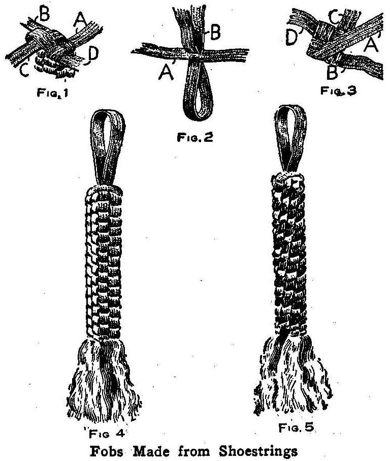
Fobs Made from Shoestrings
Having procured a pair of ordinary shoestrings, take both ends of
one of them and force the ends through the middle of the other,
leaving a loop 1-1/2 in. long, as shown in Fig. 2. In this
sketch, A is the first string and B is the second, doubled and
run through the web of A. Take hold of the loop and turn it as
shown in Fig. 2, allowing the four ends to hang in four
directions. Start with one end, the one marked A, in Fig. 1, for
instance, and lay it over the one to the right. Then take B and
lay it over A, and the one beneath C; lay Cover B and the one
under D, and then lay D over C and stick the end under A. Then
draw all four ends up snugly. Commence the next layer by laying
the end A back over B and D; D over A and C; C over D and B, then
B over C and the end stuck under A. Proceed in the same manner
and keep on until about 1-1/2 in. of the ends remain unwoven.
Four pins stuck through each corner and into the layers will hold
the ends from coming apart. The ends of the strings are raveled
out so as to make a tassel. This will make a square fob which
will appear as shown in Fig. 4.
A round fob is made in a similar way, taking the same start as
for the square fob, but instead of reversing the ends of each
alternate layer, always lap one string, as at A in Fig. 3. over
the one to its right, as B, slipping the last end of the four
strings under and tightening all, as in making the square fob.
Fasten the ends with pins and ravel out for a tassel. The round
fob is shown in Fig. 5.
A fob in the shape of a horseshoe can be made by taking four
shoestrings and tying a small string around the middle of them,
then weaving the layers both ways from the point where the
strings are tied. A loop, 1-1/2 in. long, is left out at the
center before starting on one side. The loop is for attaching the
fob to the watch. After the weaving is complete and the tassel
ends made, a small stiff wire is forced through the center to
form the shape of a horseshoe.
Other designs can be made in the same manner. Strings of
different colors will make up a very pretty fob, especially if
silk strings are used.
Contributed by John P. Rupp, Monroeville, Ohio.
How to Make a Table Mat of Leather
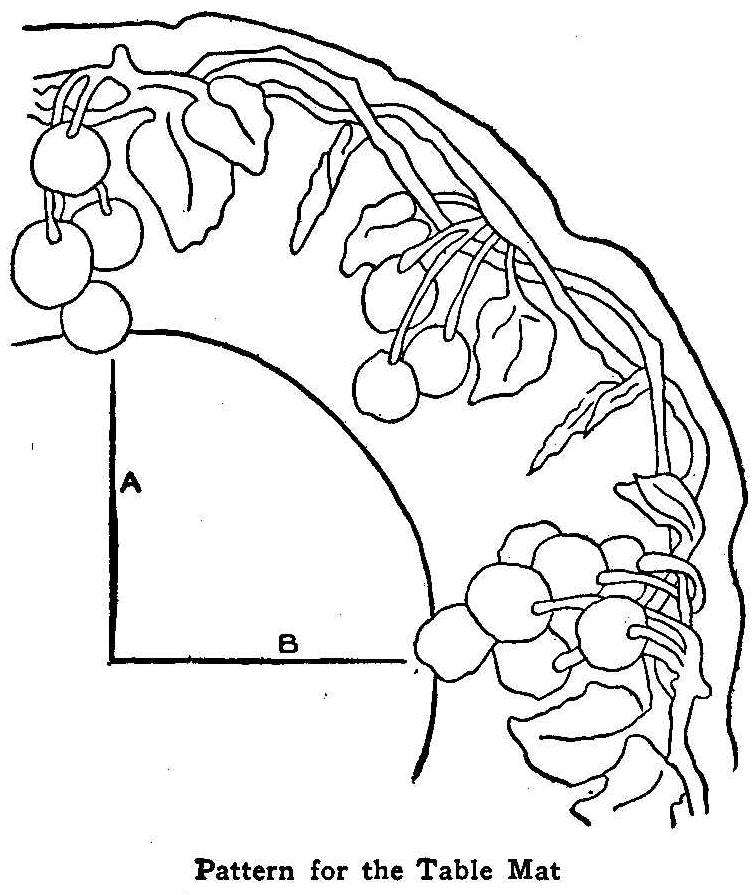
Pattern for the Table Mat
The table mat, the design of which is shown herewith, is to be
made of leather. It may be made of Russian calf and the
background modeled down as has been described in several previous
articles dealing with leather work. To do this the leather is
moistened on the back side just enough to make the leather take
the impression of the tool, but not enough to make the moisture
show through on the face. Any smooth piece of steel, such as a
nut pick, that will not cut or scratch the leather and will make
a V-shaped depression will do.
A second method is to secure a piece of sheepskin and, using the
reverse side, outline the design by means of a pyrographer’s
outfit. This manner of treating leather is so common that it
needs no description.
A third method is to secure a piece of sheep or goat skin, trace
the design on the reverse side by means of carbon paper, and put
the outline and design in with brush and stains such as are sold
for this purpose.
The accompanying pattern shows but one-fourth of the mat. Draw
the one-fourth on paper to the size desired and then fold on
lines A and B, tracing this one-fourth on the other parts by the
insertion of double-surfaced carbon paper.
On the calfskin the pattern is to be held on the leather and the
tool worked over the pattern to get the outline transferred.
After this the pattern is to be removed and the leather modeled.
Sad Iron Polisher
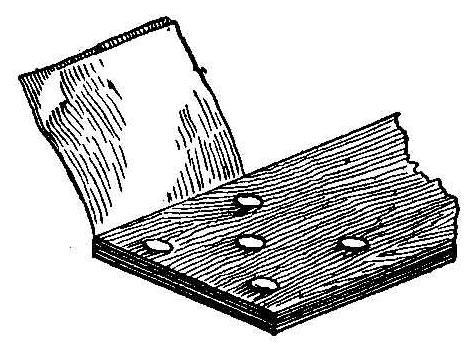
A small amount of wax is necessary on an iron for successful
work. The wax is usually applied by hand to the heated surface of
the iron. A much better and handier way is to bore five or six
holes in one end of the ironing board to a depth of half its
thickness, filling them with wax, beeswax or paraffin, and
covering them over with two thicknesses of muslin.
The rubbing of the hot iron over this cloth absorbs just enough
of the wax to make the iron work smoothly. When the supply of wax
is exhausted, it can be easily renewed.
Contributed by A. A. Houghton, Northville, Mich.
Making Coins Stick to Wood by Vacuum
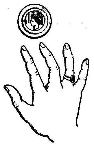
Take a quarter and place it flat against a vertical surface of
wood such as the side of a bookcase, door facing or door panel,
and strike it hard with a downward sliding motion, pressing it
against the wood. Take the hand away and the coin will remain on
the woodwork. The striking and pressure expel the air between the
quarter and the wood, thus forming a vacuum sufficient to hold
the coin.
Simple and Safe Method for Sending Coins by Mail
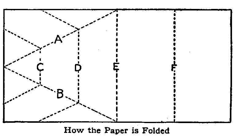
How the Paper is Folded
Sending coins by mail is not as a rule advisable, but sometimes
it becomes necessary, and usually a regular coin mailer is not
available. A very simple and secure way to wrap a coin or coins
for mailing is as follows: Procure a piece of heavy paper, nearly
as wide as the envelope is long, and about 12 in. long. Fold on
the dotted lines shown by A and B in the sketch, and slip the
coin in the pocket thus formed. Fold together on lines C, D, E
and F, making the last two folds wide enough to fit snugly in the
envelope. This method holds the coin in the center of the
envelope where it cannot work around and cut through the edges.
Contributed by O. J. Thompson, Petersburg, Ill.
Mounting Photographs in Plaster Plaques
Purchase a few pounds of plaster of paris from your local
druggist and select a dish of the desired shape in which to make
your cast. The size of the dish will depend on the size of the
print to be mounted. Select the print you wish to mount, those on
matte paper will work best, and after wetting, place it face down
in the dish, press into place and remove all drops of water with
a soft cloth. Be sure and have the print in the center of the
dish. Earthen dishes will be found more convenient, although tin
ones can be used with good success, says Photographic Times.
Mix same of the plaster in clear water so it will be a little
thick. Enough plaster should. be mixed to cover the bottom of the
dish about 1/2 in. thick. Pour the plaster into the dish over the
print and allow to stand until it becomes quite hard. The cast
can then be removed and the print should be fast to it. If the
print or plaster is inclined to stick, take a knife and gently
pry around the edges and it can be removed without breaking.
Prints of any size may be used by having the mold or dish large
enough to leave a good margin. This is a very important point as
it is the margin that adds richness to all prints. Platinum or
blueprint papers work well, but any kind that will not stick may
be used. After the plaster has thoroughly dried, any tint may be
worked on the margin by the use of water colors; if blueprints
are used, it is best to leave a plain white margin.
Iron Rest for an Ironing Board
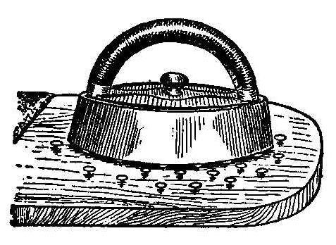
A flatiron rest can be made on an ironing-board by driving a
number of large tacks into one end of the board. The tacks should
be about 1 in. apart and driven in only part way, leaving about
1/4 in. remaining above the surface of the board. The hot iron
will not burn the wood and it cannot slip off the tacks. This
iron rest is always with the board and ready when wanted.
Contributed by Beatrice Oliver, New York, N. Y.
Instantaneous Crystallization
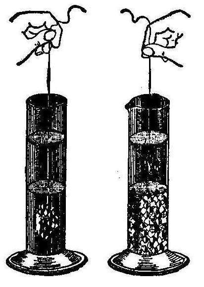
Dissolve 150 parts of hyposulphite of soda in 15 parts of water
and pour the solution slowly into a test tube which has been
warmed in boiling water, filling the same about one-half full.
Dissolve in another glass 100 parts of acetate of soda in 15
parts of boiling water. Pour this solution slowly on top of the
first in such a way that it forms an upper layer, without
mixing the solutions. The two solutions are then covered over
with a thin layer of boiling water and allowed to cool.
Lower into the test tube a wire, at the extremity of which is
fixed a small crystal of hyposulphite of soda. The crystal
traverses the solution of acetate without causing trouble, but
crystallization will immediately set in as soon as it touches the
lower hyposulphite of soda solution, as shown at the left in the
sketch.
When the hyposulphite of soda solution becomes crystallized,
lower in the upper solution a crystal of acetate of soda
suspended by another wire, as shown in the right of the sketch,
and this will crystallize the same as the other solution.
Decoloration of Flowers by Fumes of Sulphur
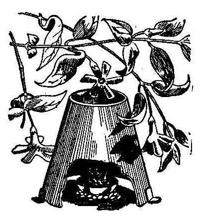
Dissolve some sulphur in a small dish which will inflame by
contact with air thus forming
sulphuric acid fumes. Cover the
dish with a conical chimney made of tin and expose to the upper
opening the flowers that are to be decolored. The action is very
rapid and in a short time myrtle, violets, bell flowers, roses,
etc., will be rendered perfectly white.
How to Preserve Egg Shells
Many naturalists experience difficulty in preserving valuable egg
shells. One of the most effective ways of preserving them is as
follows: After the egg is blown, melt common beeswax and force it
into the shell with a discarded fountain pen filler. Set in a
cool place until the wax hardens. The most delicate shells
treated in this manner can be handled without fear of breaking,
and the transparency of the wax will not alter the color,
shading, or delicate tints of the egg.
Contributed by L. L. Shabino, Millstown, South Dakota.
Homemade Phonograph
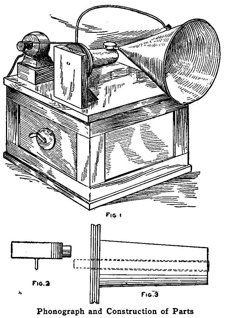
Phonograph and Construction of Parts
Make a box large enough to hold four dry cells and use it as a
base to mount the motor on and to support the revolving cylinder.
Anyone of the various battery motors may be used to supply the
power. The support for the cylinder is first made and located on
the cover of the box in such a position that it will give ample
room for the motor. The motor base and the support are fastened
by screws turned up through the cover or top of the box. The
location of these parts is shown in Fig. 1.
The core for holding the cylindrical wax records is 4-1/2 in.
long and made of wood, turned a little tapering, the diameter at
the small or outer end being 1-5/8 in., and at the larger end,
1-7/8 in. A wood wheel with a V-shaped groove on its edge is
nailed to the larger end of the cylinder. The hole in the core is
fitted with a brass tube, driven in tightly to serve as a
bearing. A rod that will fit the brass tube, not too tightly, but
which will not wobble loose, is threaded and turned into the
upper end of the support. The core with its attached driving
wheel is shown in Fig. 3. The dotted lines show the brass bearing
and rod axle. The end of the axle should be provided with a
thread over which a washer and nut are placed, to keep the core
from coming off in turning.
The sound box, Fig. 2, is about 2-1/2 in. in diameter and 1 in.
thick, made of heavy tin. The diaphragm, which should be of thin
ferrotype tin, should be soldered to the box. The needle is made
of a piece of sewing needle, about 1/8s in. long, and soldered to
the center of the diaphragm. The first point should be ground
blunt, as shown in the sketch. When soldering these parts
together, take care to have the diaphragm lie perfectly flat and
not made warping by any pressure applied while the solder is
cooling.
The tin horn can be easily made, attached to the sound box with a
piece of rubber hose and held so it will swing the length of the
record by a rod attached to the top of the box, as shown. The
motor can be controlled by a small three or four-point battery
rheostat.
Contributed by Herbert Hahn, Chicago, Ill.
A Substitute for a Compass
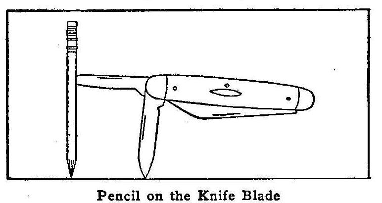
Pencil on the Knife Blade
An easy way to make a pencil compass when one is not at hand, is
to take a knife with two blades at one end, open one to the full
extent and the other only halfway. Stick the point end of the
fully open blade into the side of a lead pencil and use the
half-open blade as the center leg of the compass. Turn with the
knife handle to make the circle.
Contributed by E. E. Gold. Jr., Victor, Colo.
A Novel Rat Trap
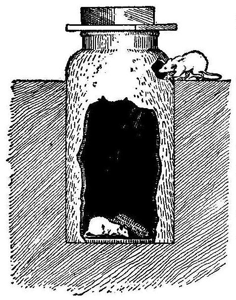
A boy, while playing in the yard close to a grain house, dug a
hole and buried an old-fashioned fruit jug or jar that his mother
had thrown away, says the Iowa Homestead. The top part of the jug
was left uncovered as shown in the sketch, and a hole was broken
in it just above the ground. The boy then placed some shelled
corn in the bottom, put a board on top, and weighted it with a
heavy stone. The jug had been forgotten for several days when a
farmer found it, and, wondering what it was, he raised the board
and found nine full-grown rats and four, mice in the bottom. The
trap has been in use for some time and is opened every day or two
and never fails to have from one to six rats or mice in it.
A Nut-Cracking Block
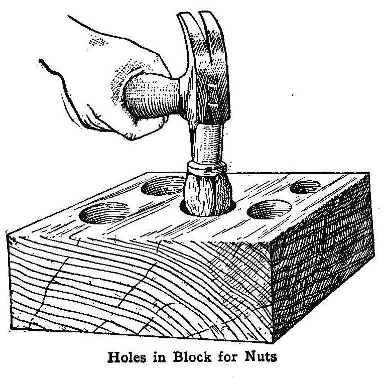
In the sketch herewith is shown an appliance for cracking nuts
which will prevent many a bruised thumb. To anyone who has ever
tried to crack butternuts it needs no further recommendation. The
device is nothing more than a good block of hardwood with a few
holes bored in it to fit the different sized nuts. There is no
need of holding the nut with the fingers, and as hard a blow may
be struck as desired. Make the depth of the hole two-thirds the
height of the nut and the broken pieces will not scatter.
Contributed by Albert O’Brien, Buffalo, N. Y.
A Jelly-Making Stand
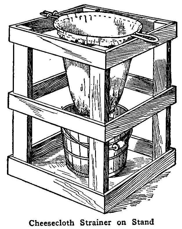
Cheesecloth Strainer on Stand
Every housewife who makes jelly is only too well acquainted with
the inconvenience and danger of upsets when using the old
method of balancing a jelly-bag on a couple of chairs stood on
the kitchen table, with the additional inconvenience of having a
couple of chairs on the kitchen table out of commission for such
a length of time.
The accompanying sketch shows how a stand can be made from a few
pieces of boards that will help jelly makers and prevent the
old-time dangers and disadvantages. The stand can be stood in the
corner of the kitchen, or under the kitchen table where it will
be out of danger of being upset.
Contributed by Lyndwode, Pereira, Ottawa, Can.
How to Make an Egg-Beater
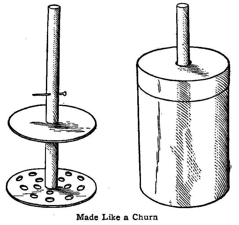
Made Like a Churn
There is no reason why any cook or housewife should be without
this eggbeater, as it can be made quickly in any size. All that
is needed is an ordinary can with a tight-fitting cover—a
baking-powder can will do. Cut a round piece of wood 3 in. longer
than the length of the can. Cut a neat hole in the cover of the
can to allow the stick to pass through, and at one end of the
stick fasten, by means of a flatheaded tack, a piece of tin, cut
round, through which several holes have been punched. Secure
another piece of heavier tin of the same size, and make a hole in
the center to pass the stick through. Put a small nail 2 in.
above the end of the dasher, which allows the second tin to pass
up and down in the opposite direction to the dasher. This beater
will do the work in less time than the regular kitchen utensil.
Contributed by W. A. Jaquythe, Richmond, Cal.
Cart Without an Axle
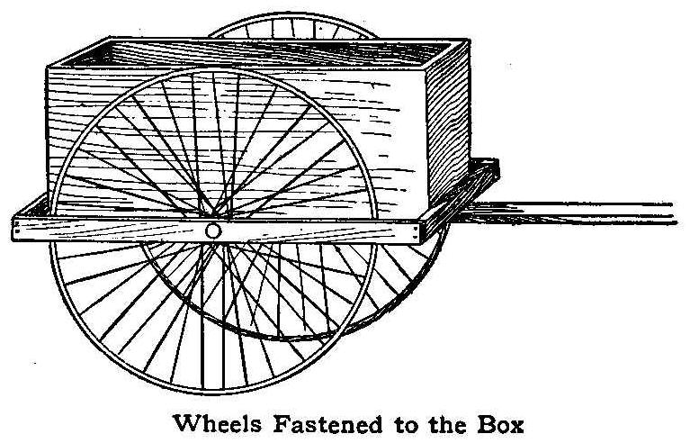
Wheels Fastened to the Box
The boy who has a couple of cart wheels is not always lucky
enough to have an axle of the proper length to fit the wheels. In
such a case the cart can be constructed as shown in the
illustration. This cart has no axle, each wheel being attached
with a short pin for an axle, on the side and at the lower edge
of the box. The outer end of the pin is carried on a piece of
wood extending the full length of the box and supported by
crosspieces nailed to the ends, as shown.
Contributed by Thos. De Loof, Grand Rapids, Mich.
An Illuminated Target
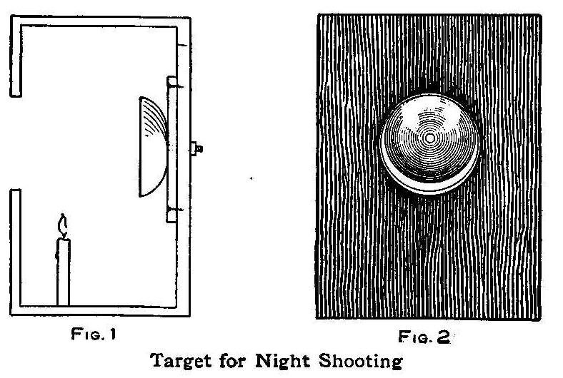
Fig. 1 Fig. 2.
Target for Night Shooting
My youthful nephews some time ago were presented with an air
rifle and it worked so well that it became necessary for me to
construct a target that would allow the fun to be carried on at
night.
I reversed a door gong, screwed it on the inside of a store box,
and fitted two candles on the inside to illuminate the bullseye.
The candles, of course, were below the level of the bullseye. The
position of the candles and gong are shown in Fig. 1. At night
the illuminated interior of the bell could be plainly seen as
shown in Fig. 2.
Contributed by James M. Kane, Doylestown, Pa.
Sawing Sheet Metal
Sheet metal placed between two boards in the jaws of a vise and
clamped tightly, can be sawed easily with a hacksaw.
Feed Box for Chickens
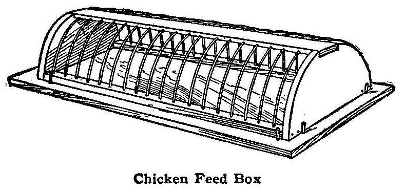
Chicken Feed Box
The sketch shows the construction of a feed box designed to
prevent the scattering of feed and give the coward rooster as
much chance to fatten as the game cock. The base may be made of a
1/2-in. board, 1 ft. wide and 3 ft. long, although any of the
dimensions may be varied to suit special requirements. The ends
are semi-circular pieces with a notch, 1/4 in. deep and 3 in.
wide, cut in the center of the rounding edge. The ends are
connected together with a piece of wood set in the notches. The
strip of wood is 1/4 in. thick, 2 in. wide and as long as the
box. Notches 1/8 in. wide and 1/8 in. deep are cut on the under
side of this piece of wood, 1-1/2 in. apart. Heavy pieces of wire
are bent in the form of a semi-circle, as shown. The wires are
set in the 1/8-in. notches cut on the under side of the top piece
of wood. The ends of the wires are set in holes in wood pieces
joining the bases of the end pieces. The baseboard and top are
separable.
Contributed by Maurice Baudier, New Orleans, La.
A Book Rest
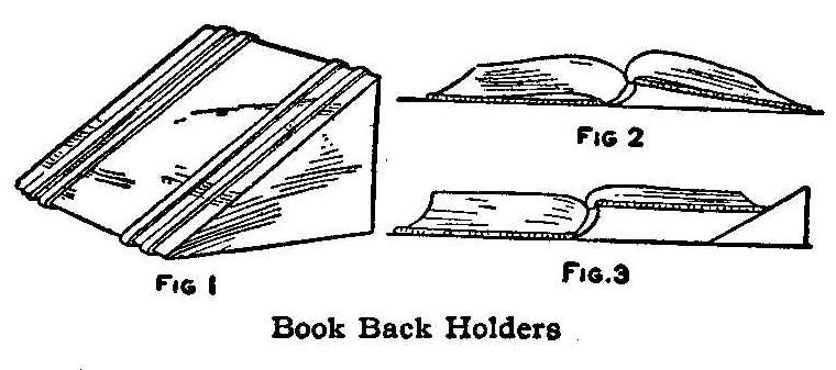
Book Back Holders
A book that does not open flat is rather inconvenient to write in
when one of its sides is in the position shown in Fig. 2. A
wedge-shaped piece of metal, stone or wood, as shown in Fig. 1,
will, when placed as in Fig. 3, raise the sloping half to the
level of the other pages. Cover the block with rubber, wide
rubber bands or felt, to prevent its scratching the desk top. The
block can also be used as a paperweight.
Window Shelf for Flower Pots
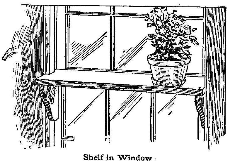
Shelf in Window
On the ledge formed by the top part of the lower sash of the
window I fitted a board 7 in. wide into each side of the casing,
by cutting away the ends. I placed a small bracket at each end of
the shelf, so that it would fit solidly against the lower window
sash to support the weight of the plants.
One of the brackets I nailed to the shelf and the other I held in
place with a hinge, the reason being that if both were solid, the
shelf could not be put on the window, as one end must be dropped
in place before the other. Such a shelf will hold all the plants
a person can put on it. When not in use, it can be removed
without marring the casing.
Contributed by G. A. Wood, West Union, Ia.
Magnet for the Work Basket
Tie a ribbon or strong string to the work basket and fasten a
large magnet to the other end. Needles, scissors, etc., can be
picked up without any trouble. This device is very convenient for
invalids.
Contributed by Nellie Conlon, Worcester, Mass.
Knife Made from a Hack-Saw Blade
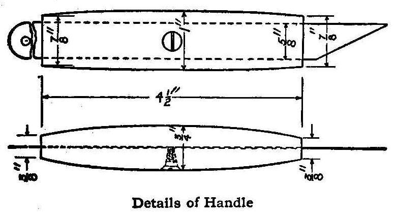
Details of Handle
A very serviceable knife with excellent cutting qualities can be
made easily from a discarded hack-saw blade. The dimensions given
in the sketch make a knife of convenient size. The saw teeth are
ground off on an emery wheel or grindstone to a smooth edge
parallel with the back edge. For the handle, take two pieces of
hard wood, dressing one surface of each piece, and cut a groove
as wide and thick as the saw blade. Place the blade in the groove
and glue the two dressed sides of the wood together. After the
glue has dried, the blade can be pulled out of the groove and the
wood shaped to any desired form. A small wood-screw is put
through one side of the handle to prevent the blade from sliding.
After completing the handle, the blade is put back into the
groove and sharpened to a cutting edge.
Contributed by H. A. Hutchins, Cleveland, Ohio.
Killing Mice and Rats
A simple and inexpensive means for killing mice and rats is to
leave yeast cakes lying around where they can eat them.
Contributed by Maud McKee, Erie, Pa.
Roller Coaster Illusion Traveling Up an Incline
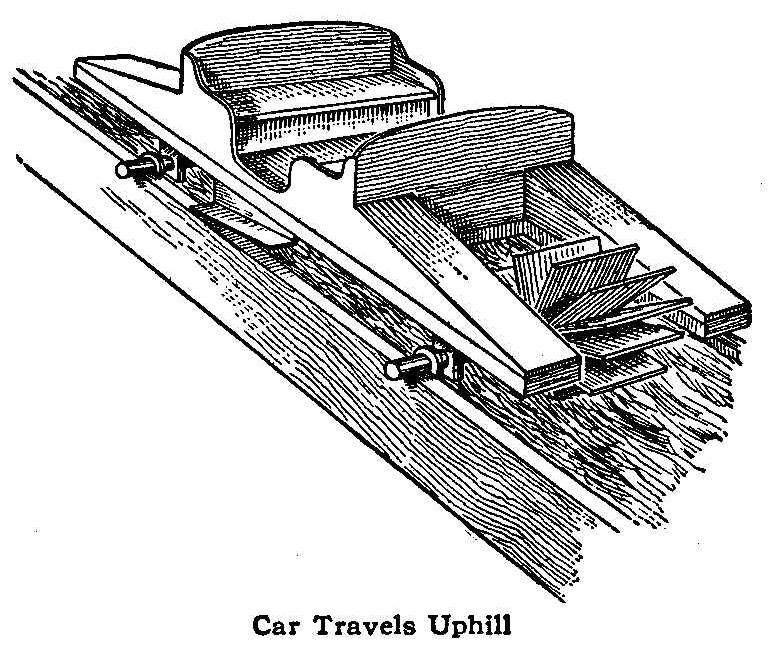
Car Travels Uphill
A toy car with a paddle wheel and a shaft on both ends traveling
upward on a chute in which water is flowing down, is shown in the
accompanying sketch. The paddle wheels travel in a reverse
direction causing the ends of the axles to roll on the edge of
the chute, thus carrying the car up the incline. If a rack is
used on each side of the chute and a small pinion on the ends of
the axles, a positive upward movement of the car will be
obtained.
Contributed by W. S. Jacobs, Malden, Mass.
Block for Planing Octagonal Wood Pieces
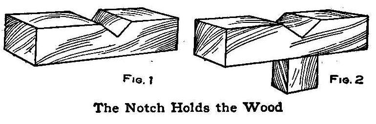
The Notch Holds the Wood
The little device shown in the illustration will be found very
useful in any workshop. Two or three of them will be necessary
for planing long pieces. Each one is made of a hardwood block, 1
in. square and 4 in. long. A notch is cut in one side, as shown
in Fig. 1, so a piece of wood which has been planed square will
fit in it. Put a screw in the end of each piece and fasten it
down to the bench. If desired, a tenon may be made on the bottom
of each block, as shown in Fig. 2, to fit a mortise cut in the
bench. Place the blocks far enough apart so the board to be
planed will rest firmly in the notches. Plane the board square
first and then place it in the notches and plane the corners down
to the proper dimensions.
Contributed by Willie Woolsen, Cape May Point, N.J.
A Letter Holder of Pierced Metal
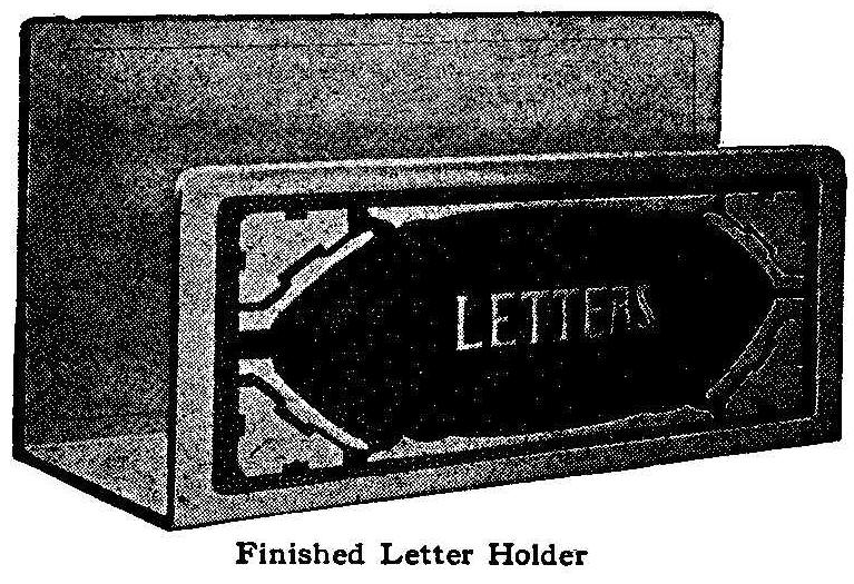
Finished Letter Holder
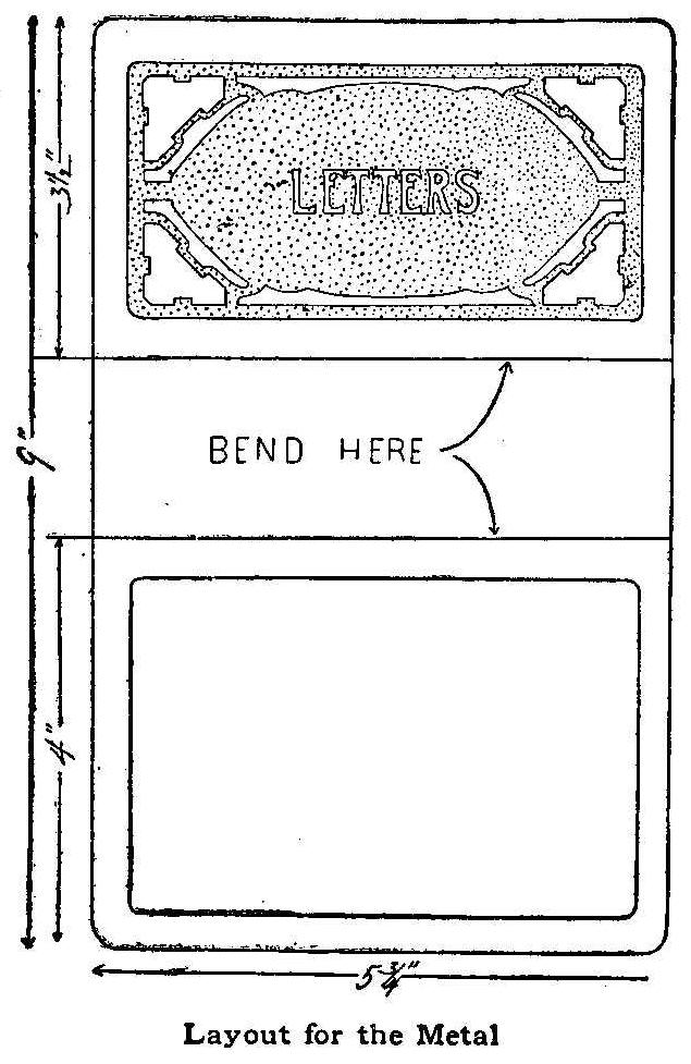
Layout for the Metal
The letter holder shown in the illustration will be found
convenient for holding outgoing letters that await the
postman’s coming. It can be made of either copper or brass and
need not be of very heavy material. Gauge 22 will be sufficiently
heavy. One sheet of metal, 6 by 9-1/2 in., a board on which to
work it, and an awl and hammer, will be needed.
Prepare a design for the front. If one such as is shown is to be
used, make one-quarter of it first, and then get the other parts
by folding on the center lines and tracing. This will insure
having all parts alike. The letters can be put on afterward.
Fasten the metal to the board, using tacks and nailing outside of
the required space, in the waste metal. Trace the design on the
metal with carbon paper; or, if desired, paste the paper design
right on the metal. With an awl pierce the metal between the
marginal line and the design, as shown. The holes should be
uniform along the outlines but should be pierced promiscuously
otherwise. On the back, only the marginal line is to be
pierced.
Remove the metal, together with the paper if the latter was
pasted to the metal, and trim off the surplus metal where the
tacks had been placed. File off any sharpness so that the hand
may not be injured in handling it. Place the metal on the edge of
a table or between two boards, and bend on the two lines
indicated in the drawing, to right angles.
A good finish is obtained by just letting the copper age with its
natural color. If any polishing is required, it should be done
before the metal is fastened to the board and pierced.
Imitating Ground Glass
Make a mixture of white lead
in oil, 1 part; varnish, 3/4 part;
turpentine, 1/4 part, and add
sugar of lead as a dryer. Make a
very thin paint of this and use a broad, flat brush, says Master
Painter. With care you may succeed in getting the paint on quite
evenly all over, which is desirable. One coat will do. If it
becomes necessary to remove this coating for renewal, it may be
effected by an application of potash
lye, or the old may be
renewed by a coating of a mixture of 2 parts
hydrochloric acid,
2 parts white vitriol, 1 part sulphate of copper (blue vitriol)
and 1 part of gum arabic, applied by means of a brush.
Draw before Cutting
A detail drawing made of a piece of furniture before starting the
work will often save time and mistakes.
Making “Spirits” Play a Violin
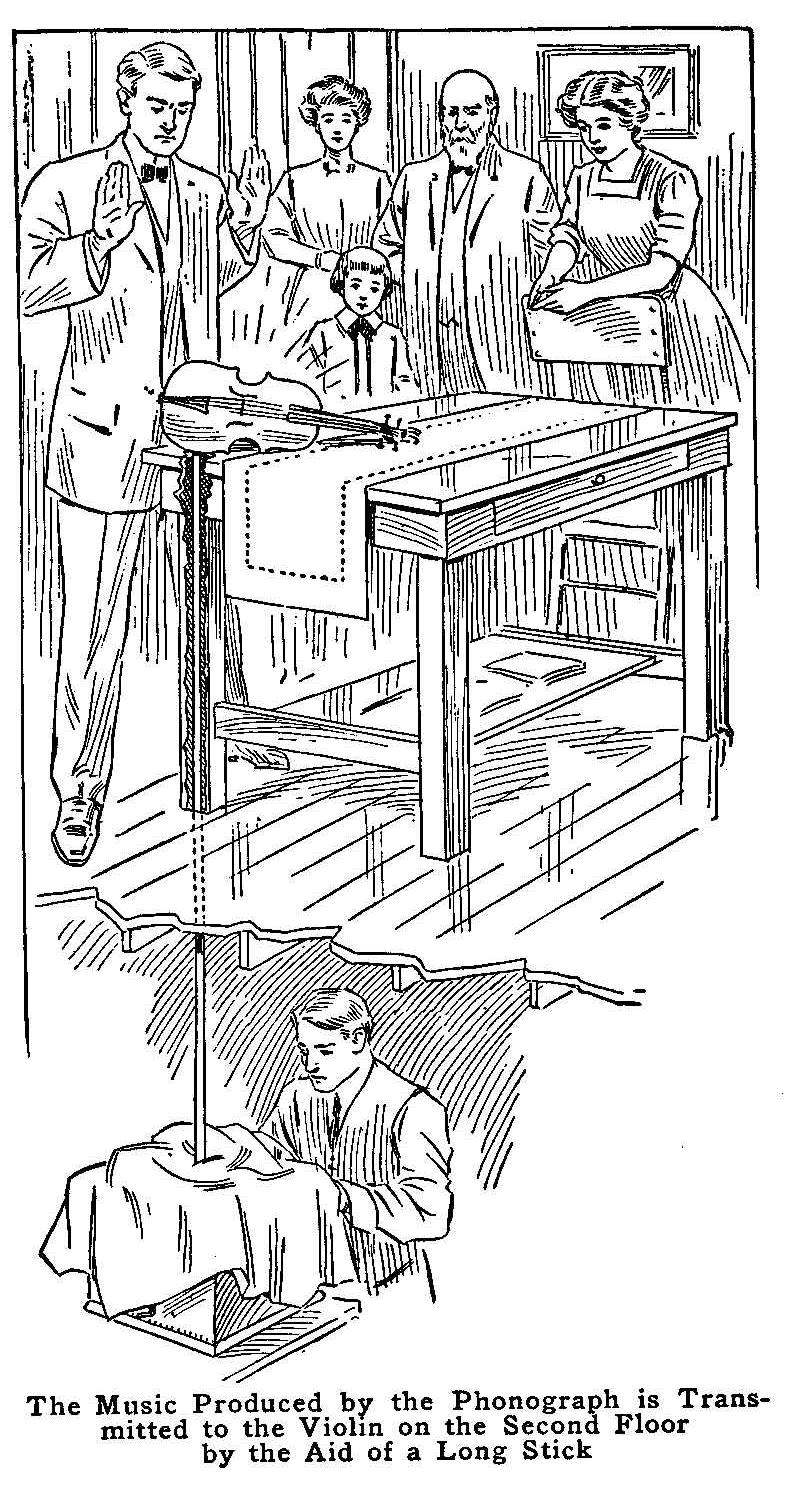
The Music Produced by the Phonograph is Transmitted to the Violin
on the Second Floor by the Aid of a Long Stick
A very pretty trick, that can be worked in your own parlor, will
produce as much sensation as a fake “medium.” In all appearance,
a violin, mandolin or guitar, placed on a table, will begin to
produce music simply through stamping the foot and a few passes
of the hand. The music will not sound natural, but weird and
distant.
The trick is done by placing the end of a small stick on a music
box in the basement of the house and allowing the other end to
pass up through the floor and table top so it will project about
1/16 in. The stick may be placed by the side of, behind or
through the center of a table leg. Be careful not to have any
obstruction in the way of the stick. The instrument is placed
sideways on the protruding end of the stick. The “fake” work of
invoking the “spirit” is performed and ended by stamping the
foot, which signals the operator in the basement to start the
machine, and the violin seemingly produces music without anyone
touching it.
So impressive are the results, that many people really think the
spirits of the departed are playing the violin with unseen hands.
The music is transmitted through the stick from the music box to
the violin.
Sizing a Threaded Hole
It sometimes becomes necessary to transfer the size of a threaded
hole from some out-of-the-way place to the shop in order to make
a piece to fit it. With proper tools this is easy; without them,
it might be difficult. One thing is always at hand and that is
wood. Whittle a stick tapering until it starts in the hole. Then
turn it into the hole and a fair thread will be made on the wood.
The stick can be carried in the pocket without risk of changing
the size, as would be the case with ordinary calipers.
Leaded-Glass Fire Screen
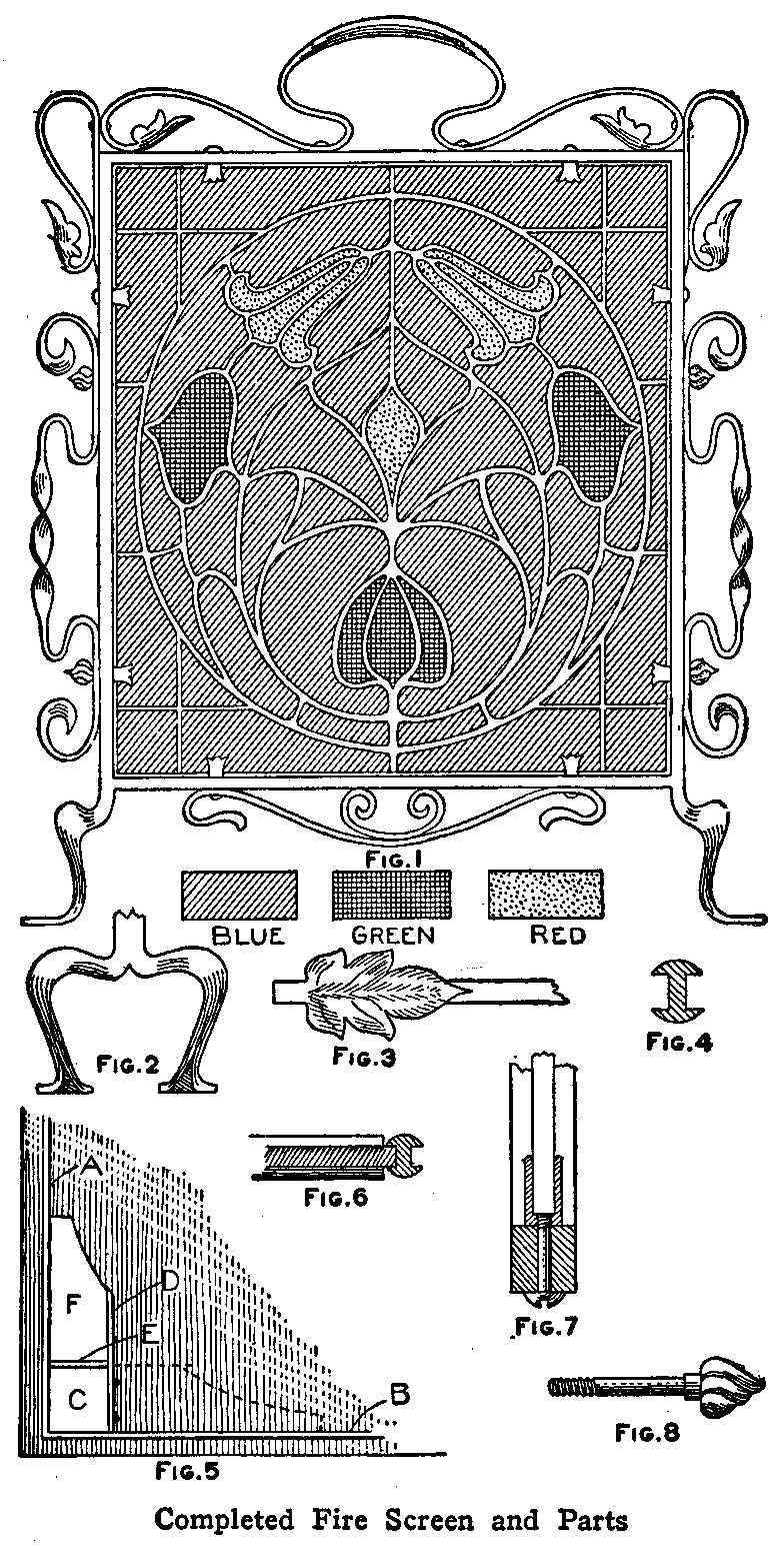
Completed Fire Screen and Parts
The main frame of the fire screen shown in Fig. 1 is made from
two pieces of 1/2-in. square bar iron. The longest piece, which
should be about 5-1/2 ft. long, is bent square so as to form two
uprights, each 28 in. long and measuring 26 in. across the top.
The bottom crosspiece can be either riveted or welded to the
uprights. Two pairs of feet, each 6 in. long and spread about 8
in. apart, are shaped as shown in Fig. 2. These are welded to the
lower end of the uprights.
The ornamental scrollwork on the frame is simple and effective,
and is easy to construct, says Work, London. The scrolls are
attached to the frame by means of 3/16-in. round-head machine
screws. The leaf ornament at the termination of the scroll is
shaped and embossed as shown in Fig. 3. The metal used for the
scrolls is 3/16 in. thick by 1/2 in. wide. The leaf ornament is
formed by turning over the end of a piece of metal and working it
together at a welding heat, and then shaping out the leaf with’ a
chisel and files, after which they are embossed with a ball-peen
hammer.
The center is made from colored glass of special make for leaded
work. The design is formed in the lead,
of which a cross section is shown in Fig. 4. Use care to give the
lead a symmetrical
outline. The design should be drawn full size on a large sheet of
heavy paper and the spaces to be occupied by the lead cut out so
as to leave the exact size and shape of each piece of paper the
same as wanted for each piece of glass. These are used as
patterns in marking the glass for cutting. The glass is cut the
same as ordinary window glass. The glass, lead, border and
special flux can be purchased from an art glass shop.
After the glass is cut, the work of putting the pieces together
with the lead between them is begun. Secure a board as wide as
the screen—several narrow boards put together will do and begin
by placing one vertical side border, A, Fig. 5, and the base
border, B, on it as shown. Place the corner piece of glass, C, in
the grooves of the borders, cut a long piece of
lead, D, and hold
it in place with two or three brads or glazier’s points. The
piece of lead
E is cut and a small tenon joint made as shown in
Fig. 6. While the piece of lead D,
Fig. 5, is held by the brads,
the piece E can be fitted and soldered. The soldering is done
with a hot soldering iron and wire solder, using rosin as a flux,
or, better still, special flux purchased for this purpose. After
the joints are soldered, the piece of glass F is put in place and
the lead held with brads as
before until the cross leads are
fitted and soldered. The brads are then removed, the glass piece
as shown by the dotted lines put in, and the leads around it held
with brads until the crosspieces are put in and soldered. This
method is pursued until the glass is complete, then the two
remaining vertical and top pieces of border are put on and all
corners soldered.
The leaded glass is held in the iron frame by means of eight
U-shaped clips, as shown in Fig. 7. A hole is drilled in the
frame for the retaining screw, the latter being tapped to the
base of the clip. Special screws may be made with ornamental
heads, as shown in Fig. 8, and used for securing the side scrolls
and clips together.
A Revolving Teeter Board
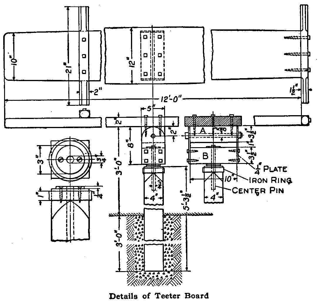
Details of Teeter Board
The accompanying sketch shows the details of a revolving teeter
board for the children’s playground that can be constructed in a
few hours. Secure a post, not less than 4 in. square and of the
length given in the drawing, and round the corners of one end for
a ring. This ring can be made of 1-in. strap iron and it should
be shrunk on the post. Bore a 3/4-in. hole in the end of the post
for the center pin to rest in. Make three washers 3-in. in
diameter and 1/4 in. thick and drill 3/4-in. holes through their
centers. Drill and countersink two smaller holes for 2-in. wood
screws in each washer. Fasten one of these washers to the top of
the post as shown. The post is now ready to be set in the ground.
Coarse gravel should be packed tightly about it to make it solid.
Concrete is much better if it can be secured.
To make the swivel you will need two 1/4 by 5 by 8-in. plates,
rounded at the top as shown, and two wood blocks, A and B, each
3-1/2 by 5 by 10 in. Drill the lower ends of the plates for four
2-1/2-in. lag screws and the upper ends for a 5/8-in. bolt.
Fasten the plates to the block B, then drill a 3/4-in. hole as
shown and fasten the two remaining washers to the block, one on
each side and central with the hole. Bore a 5/8-in. hole
lengthwise through the block A for the 5/8-in. rocker bolt. This
bolt should be 11-1/2 in. long.
The teeter board is made of a 2 by 12-in. plank about 12 ft.
long. It should be slightly tapered from the center to the ends.
Two styles of hand holds are shown, but the one on the left is
the one most generally used. The handles are rounded at the ends
and are fastened to the board with lag screws or bolts. The block
A is fastened to the board with lag screws and should be a
working fit between the two plates where it is held by means of
the 5/8-in. bolt. The center pin is 3/4-in. in diameter and about
9 in. long.
Contributed by W. H. Dreier, Jr., Camden, N. J.
Home-Made Pot Covers
Empty thread spools and the tins used as extra inside covers in
lard cans are usually thrown away, but these can be put to good
use as kettle covers, if they are made up as follows: Saw the
spool in half as shown, make a hole in the center of the tin and
run a screw or nail through the spool and the tin; then flatten
its end on the under side. This will make an excellent cover for
a pot.
Contributed by Maurice Baudier, New Orleans, La.
An Outdoor Gymnasium Part I-The Horizontal Bar
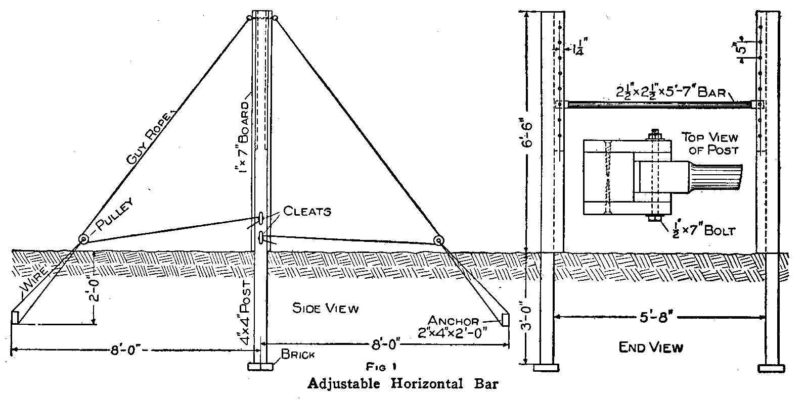
Adjustable Horizontal Bar
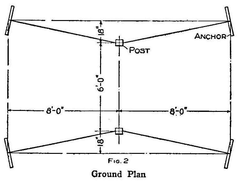
Ground Plan
Gymnastic apparatus costs money and needs to be housed, because
it will not stand the weather. Gymnasiums are not always
available for the average boy who likes exercise and who would
like to learn the tricks on horizontal and parallel bars, horse
and rings, which all young athletes are taught in regular
gymnastic courses.
Any small crowd of boys—even two—having a few simple tools, a
will to use them and the small amount of money required to buy
the necessary wood, bolts and rope, can make a first class
gymnasium. If trees are convenient, and some one can swing an
axe, the money outlay will be almost nothing. The following plans
are for material purchased from a mill squared and cut to length.
To substitute small, straight trees for the squared timbers
requires but little changes in the plans.
The most important piece of apparatus in the gymnasium is the
horizontal bar. Most gymnasiums have two: one adjustable bar for
various exercises and a high bar for gymnastic work. The outdoor
gymnasium combines the two. The material required is as follows:
2 pieces of wood, 4 in. square by 9-1/2 ft. long; 4 pieces, 2 by
4 in. by 2 ft. long; 4 pieces, 1 by 7 in. by 6-1/2 ft. long; 4
filler pieces, 3/4 by 3 in. by 3 ft. 9 in. long and 1 piece,
2-1/2 in. square by 5 ft. 7 in. long. This latter piece is for
the bar and should be of well seasoned, straight-grained hickory.
It makes no difference what kind of wood is used for the other
pieces, but it is best to use cedar for the heavy pieces that are
set in the ground as it will take years for this wood to rot.
Ordinary yellow pine will do very well. The four 7-in. boards
should be of some hard wood if possible such as oak, hickory,
maple, chestnut or ash. The other material necessary consists of
2 bolts, 1/2 in. in diameter and 7 in. long; 16 screws, 3 in.
long; 4 heavy screw eyes with two 1/2-in. shanks; 50 ft. of heavy
galvanized wire: 80 ft. of 1/4-in. manila rope and 4 pulley
blocks. Four cleats are also required but these can be made of
wood at home.
Draw a line on the four 7-in. boards along the side of each from
end to end, 1-1/4-in. from one edge. Beginning at one end of
each board make pencil dots on this line 5 in. apart for a
distance of 3 ft. 4 in. Bore holes through the boards on these
marks with a 9/15-in. bit. Fasten two of these boards on each
post with the 3-in. screws, as shown in the top view of the post
Fig. 1, forming a channel of the edges in which the holes were
bored. Two of the filler pieces are fastened in each channel as
shown, so as to make the space fit the squared end of the bar
snugly. The ends of the boards with the holes should be flush
with the top of the post. This will make each pair of holes in
the 7-in. boards coincide, so the 1/2-in. bolt can be put through
them and the squared end of the bar.
Select a level place where the apparatus is to be placed and dig
two holes 6 ft. apart, each 3 ft. deep and remove all loose dirt.
The ends of the posts not covered with the boards are set in
these holes on bricks or small stones. The channels formed by the
boards must be set facing each other with the inner surfaces of
the posts parallel and 5 ft. 8 in. apart. The holes around the
posts are filled with earth and well tamped.
The hickory piece which is to form the bar should be planed,
scraped and sandpapered until it is perfectly smooth and round
except for 3 in. at each end. Bore a 9/16-in. hole through each
square end 1-1/4 in. from the end. The bar may be fastened at any
desired height by slipping the 1/2-in. bolts through the holes
bored in both the bar and channel.
Each post must be well braced to keep it rigid while a person is
swinging on the bar. Four anchors are placed in the ground at the
corners of an imaginary rectangle 9 by 16 ft., in the center of
which the posts stand as shown in Fig. 2. Each anchor is made of
one 2-ft. piece of wood, around the center of which four strands
of the heavy galvanized wire are twisted, then buried to a depth
of 2 ft., the extending ends of the wires coming up to the
surface at an angle.
The heavy screw eyes are turned into the posts at the top and
lengths of ropes tied to each. These ropes or guys pass through
the pulley blocks, which are fastened to the projecting ends of
the anchor wire, and return to the posts where they are tied to
cleats. Do not tighten the guy ropes without the bar in place, as
to do so will strain the posts in the ground. Do not change the
elevation of the bar without slacking up on the ropes. It takes
but little pull on the guy ropes to make them taut, and once
tightened the bar will be rigid.
Oil the bar when it is finished and remove it during the winter.
It is well to oil the wood occasionally during the summer and
reverse the bar at times to prevent its becoming curved. The wood
parts should be well painted to protect them from the weather.
Electrostatic Illumination
Anyone having the use of a static machine can perform the
following experiment which gives a striking result. A common
tumbler is mounted on a revolving platform and a narrow strip of
tinfoil is fastened with shellac varnish to the surface of the
glass as follows: Starting beneath the foot of the glass from a
point immediately below the stem, it is taken to the edge of the
foot; it follows the edge for about 1 in. and then passes in a
curve across the base, and ascends the stem; then it passes
around the bowl in a sinuous course to the rim, which it follows
for about one-third of its circumference; after which it descends
on the inside and terminates at the bottom. The tinfoil on the
outside of the glass is divided by cutting with a knife every 1/8
in., the parts inside and beneath the glass being left undivided.
Current is then led from a static machine to two terminals, one
terminal being connected to one end of the tinfoil strip, and
similarly the second terminal makes contact with the other end.
As soon as the current is led into the apparatus, a spark is seen
at each place where the knife has cut through the tinfoil. If the
tumbler is rotated, the effect will be as shown in the
illustration. A variety of small and peculiar effects can be
obtained by making some of the gaps in the tinfoil larger than
others, in which case larger sparks would be produced at these
points. The experiment should be carried out in a darkened room,
and under these circumstances when nothing is visible, not even
the tumbler, the effect is very striking.
Balloon Ascension Illusion
By C. W. Nieman
In these days of startling revelations in air-craft flight we are
prepared to see any day some marvelous machine driven bird
cutting figure-eights all over the sky above our heads. One boy
recently took advantage of this state of expectancy to have an
evening’s harmless amusement, through an illusion which deceived
even the most incredulous. He caused a whole hotel-full of people
to gaze open mouthed at a sort of “Zeppelin XXIII,” which skimmed
along the distant horizon, just visible against the dark evening
sky, disappearing only to reappear again, and working the whole
crowd up to a frenzy of excitement. And all he used was a black
thread, a big piece of cardboard and a pair of field glasses.
He stretched the thread between two buildings, about 100 ft.
apart, in an endless belt, passing through a screw-eye at either
end. On this thread he fastened a cardboard “cut-out” of a
dirigible, not much to look at in daytime, but most deceptive at
dusk. By pulling one or the other string he moved the “airship”
in either direction. He took the precaution of stretching his
thread just beyond a blackberry hedge and thus kept
over-inquisitive persons at a safe distance. He also saw to it
that there was a black background at either end so that the
reversing of the direction of the craft would not be noticed.
In attracting the crowd he had a confederate stand looking at the
moving ship through a field glass, which at once gave the
suggestion of distance, and materially heightened the illusion.
When the interest of the crowd, which at once gathered, was at
its height, the “aeronaut” pulled his craft out of sight and let
the disillusion come when the light of day laid bare his fraud.
A Cork Extractor
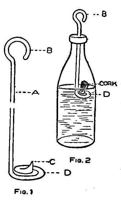
The device shown in the sketch is for removing a cork or stopper
from a bottle whether full or empty where the cork has been
pushed inside. A wire about No. 14 gauge is bent as shown at B,
Fig. 1, to fit the index finger and the other end filed to a
point C, and turned in a spiral D, so the point will be on top.
Insert this tool in the bottle as shown in Fig. 2 and place the
end D under the cork and pull up. The cork will come out easily.
Contributed by Maurice Baudier. New Orleans. La.
An Outdoor Gymnasium Part II-Parallel Bars
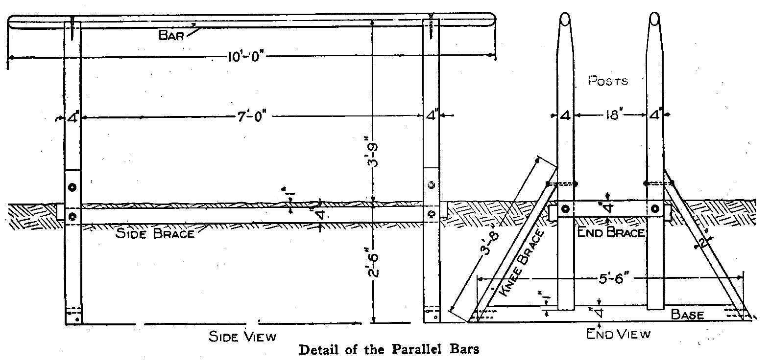
Detail of the Parallel Bars
Parallel bars hold a high place in the affection of those who
frequent gymnasiums as the best apparatus for development of the
back and shoulder muscles, as well as a promoter of ease and
grace of movement. The outdoor “gym” can have a set of these bars
with very little more labor than was required for the horizontal
bar.
The material required is as follows:
4 posts, preferably cedar, 4 in. square and 6 ft. long;
2 base pieces, 4 in. square and 5-1/2 ft. long;
2 cross braces, 2 by 4 in. by 2 ft. 2 in. long;
2 side braces, 2 by 4 in. by 7 ft. 8 in. long;
4 knee braces, 2 by 4 in. by 3 ft. 8 in. long;
2 bars of straight grained hickory, 2 by 3 in. by 10 ft. long;
4 wood screws, 6 in. long;
4 bolts, 8 in. long;
8 bolts, 7 in. long and 1 doz. large spikes.
To make the apparatus, lay off the bases as shown in the end view
and bevel the ends at an angle of 60 deg. Chisel out two notches
4 in. wide and 1 in. deep, beginning at a point 9 in. from either
side of the center. These are to receive the lower ends of the
posts. Bevel two sides of one end of each post down to the width
of the finished bar—a little less than 2 in. Cut notches in
these ends to receive the oval bars. Bevel the ends of the knee
braces, as shown in the diagram, and fasten the lower ends to the
beveled ends of the bases with the spikes. Fasten the upper ends
of the knee braces to the uprights with the 8-in. bolts put
through the holes bored for that purpose, and countersinking the
heads. Lay the whole end flat on the ground and make a mark 2-1/2
ft. from the bottom of the base up along the posts, and fasten
the end braces with their top edges flush with the marks, using
four of the 7-in bolts. Finally toe-nail the base into the ends
of the posts merely to hold them in position while the whole
structure is being handled.
Two endpieces must be made. These sets or ends of the apparatus
are to be buried in trenches dug to the depth of 2-1/2 ft., with
the distance between the two inner surfaces of the posts, which
face each other, of 7 ft. After the trenches are dug, additional
long, shallow trenches must be made connecting the posts to
receive the side braces. The function of these side braces is to
hold both ends together solidly. It is necessary to bury these
braces so they will be out of the way of the performer. The side
braces are bolted to the posts just below the cross braces, so
the bolts in both will not meet. The bars are dressed down so
that a cross section is oval as shown in the end view. They are
to be screwed to the notched ends of the uprights with the 6-in.
screws. The holes should be countersunk so they can be filled
with putty after the screws are in place. The bars should be well
oiled with linseed oil to protect them from the weather, and in
the winter they should be removed and stored.
Every piece of wood in this apparatus can be round and cut from
trees, except the bars. If using mill-cut lumber, leave it
undressed, and if using round timber leave the bark upon it as a
protection from the weather. It is well to paint the entire
apparatus, save the bars, before burying the lower part of the
end pieces. The wood so treated will last for years, but even
unpainted they are very durable. Be sure to tamp down the earth
well about the posts. A smooth piece of ground should be selected
on which to erect the apparatus.
(To be Continued.)
Combined Ladle and Strainer
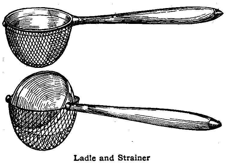
Ladle and Strainer
When using a strainer in connection with a ladle the operation
requires both hands. A convenient article where a ladle and
strainer are needed is to swing a cup-shaped strainer under the
bowl of a ladle as shown in the illustration. The strainer can be
held in place with small bands that fit loosely over the handle.
and a small tip soldered to the ladle. These will allow the
ladle to be turned, leaving the strainer always in position. A
large sized ladle, equipped with a strainer, is just the thing
for painters to dip and strain paint, while a small one is of
great assistance to the housewife for dipping and straining
soups, jellies, etc.
Contributed by W. A. Jaquythe, Richmond, Cal.
Cleaning Gloves
A solution consisting of 1 dr. of sodium carbonate and 1 qt. of
milk makes an excellent cleaner for motorists’ gloves.
Turpentine in Cutting Oil
When cutting steel or wrought iron in a lathe, milling machine,
drill press or planer, it is sometimes necessary to leave a
smooth surface. Oil, or various cutting compounds of oil, is used
for this purpose and to keep the surface cool. If a little
turpentine is added to the oil, it will greatly assist in leaving
a smooth surface. A proportion of one-quarter turpentine is good.
Center of Gravity Experiment
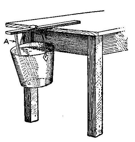
This experiment consists of suspending a pail of water from a
stick placed upon a table as shown in the accompanying sketch. In
order to accomplish this experiment, which seems impossible, it
is necessary to place a stick, A, of sufficient length, between
the end of the stick on the table and the bottom of the pail.
This makes the center of gravity somewhere near the middle of the
stick on the table, thus holding the pail as shown.
Lathe Accuracy
A heavy lathe cut will not do accurate work.
An Outdoor Gymnasium PART III-The Horse
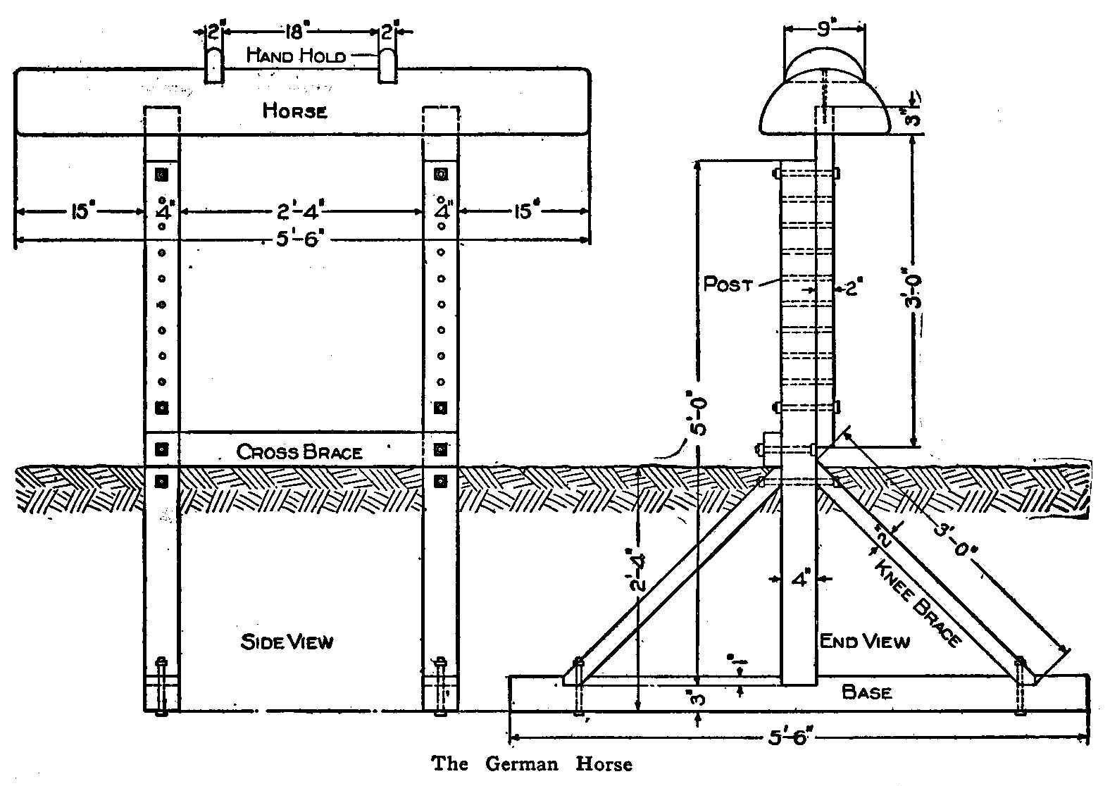
The German Horse
The German horse is that peculiar piece of apparatus which is
partly a horizontal obstruction to leap over, partly a barrier
for jumps, partly a smooth surface of long and narrow dimensions
over and about which the body may slide and swing, and partly an
artificial back for the purpose of a peculiar style of leap frog.
To make a horse for the outdoor “gym” requires no difficult work
save the preparation of the top or body of the horse. The making
of the regular gymnasium horse requires a very elaborate
wood-working and leather upholstering plant, but the one used for
outdoor work can be made of a log of wood. Procure from a saw
mill, wood yard or from the woods, one-half of a tree trunk from
a tree 9 to 15 in. in diameter—the larger the better. The
length may be anywhere from 4 to 7 ft., but 5 ft. is a good
length.
The round part of this log must be planed, scraped and
sandpapered until it is perfectly smooth, and free from knots,
projections and splinters. Hand holds must be provided next.
These are placed 18 in. apart in a central position on the horse.
Make two parallel saw cuts 2 in. apart, straight down in the
round surface of the horse until each cut is 9 in. long. Chisel
out the wood between the cuts and in the mortises thus made
insert the hand holds. Each hand hold is made of a 9-in. piece of
2 by 4-in. stud cut rounding on one edge. These are well nailed
in place.
The body of the horse is to be fastened on top of posts so that
it may be adjusted for height. It is not as difficult to make as
the horizontal and parallel bars. The material required is as
follows:
Two posts, 4 in. square by 5 ft. long;
2 adjusting pieces, 2 by 4 in. by 3 ft. 3 in. long;
1 cross brace, 2 by 4 in. by 3 ft. long;
2 bases, 4 in. square by 5-1/2 ft. long;
4 knee braces, 2 by 4 in. by 3 ft. long;
two 1/2-in. bolts, 9 in. long, to fasten the knee braces at the top;
ten 1/2-in. bolts, 7 in. long, 4 to fasten the knee braces at the bottom, 2 to fasten the cross brace and 4 to be used in fastening the adjusting pieces to the posts.
To construct, layout the bases as shown in the drawing, making
the mortises to receive the bottom ends of the posts exactly in
the center, and cut a slanting mortise 6 in. from each end to
receive the ends of the knee braces. Bevel the ends of the knee
braces and fasten the upper ends of each pair to the post with
one 9-in. bolt. Fasten the lower ends to the base with the 7-in.
bolts.
The upper end of each post should have 5/8-in. holes bored
through it parallel to the base at intervals of 3 in., beginning
1-1/2 in. from the top and extending down its length for 2 ft.
4-1/2 in. The adjusting pieces are to be bored in a similar
manner after which they are to be mortised into the under side of
the horse top 15 in. from each end, and secured with screws put
through the top and into the end of the adjusting pieces.
The bases with their posts and knee braces are buried 2 ft. 4 in.
in the ground, parallel to each other and the same distance apart
as the adjusting pieces are mortised in the horse top. When the
ground has been filled in and tamped hard, the cross brace should
be bolted in position with its lower edge resting on the ground
and connecting the two posts.
The height of the horse from the ground is adjusted by changing
the bolts in the different holes connecting the two adjusting
pieces with the two posts. Much pleasant and healthful gymnastic
exercise can be had in competitive horse jumping and leaping, the
handles providing a way to make many different leaps through,
over and around, including not only those made to see who can go
over the horse from a standing or running start at the greatest
height, but who can go over at the greatest height when starting
from the “toeing off mark” farthest away from the horse. This
horse should be located on level ground having smooth space about
it for several feet.
Spoon Rest for Kettles
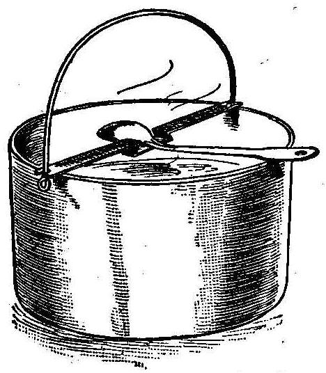
A rest for keeping spoons from slipping into kettles can be made
from a strip of metal bent as shown in the illustration. The
spring of the metal will make it easy to apply to the kettle. The
spoon placed in the rest will drain back into the kettle. The
cover can be placed on without removing the spoon.
Contributed by W. A. Jaquythe, Richmond. Cal.
Reason for Bursting of Gun Barrels
Gun barrels do not burst without a cause and usually that cause
is one of which the shooter is entirely ignorant, but
nevertheless, no one is responsible but himself, says the
Sporting Goods Dealer. Gun barrels can only burst by having some
obstruction in the barrel or by overloading with powder. Any gun
barrel can be burst by misuse or by carelessly loading smokeless
powder, but no barrel will burst by using factory loaded
ammunition, provided there is no obstruction or foreign substance
inside the barrel. When a gun barrel bursts at the breech or
chamber, it is caused by an overloaded shell, and when it bursts
in the center or near the muzzle, it is caused by some
obstruction, such as a dent, snow, water, etc.
Hand Sled Made of Pipe and Fittings
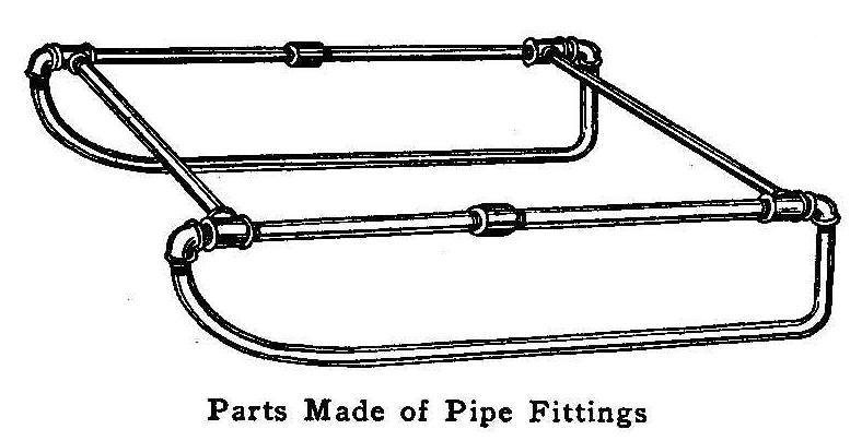
Parts Made of Pipe Fittings
The accompanying sketch shows how an ordinary hand sled can be
made of 3/4-in. pipe and fittings. Each runner is made of one
piece of pipe bent to the proper shape. This can be accomplished
by filling the pipe with melted rosin or
lead, then bending to
the shape desired, and afterward removing the rosin or
lead by
heating. Each joint is turned up tightly and well pinned or
brazed. One of the top crosspieces should have right-hand and
left-hand threads or be fitted with a union. Also, one of the top
pieces connecting the rear part to the front part of each runner
must be fitted in the same way. The top is fastened to the two
crosspieces. Such a hand sled can be made in a few hours’ time
and, when complete, is much better than a wood sled.
Contributed by James E. Noble, Toronto, Ontario.
Emergency Magnifying Glass
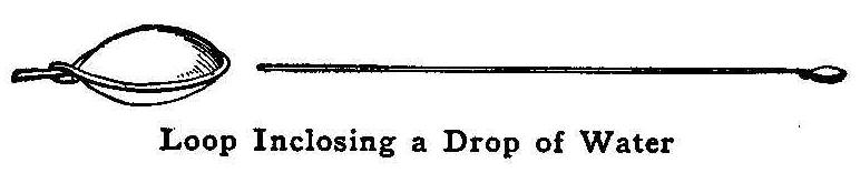
Loop Inclosing a Drop of Water
When in need of a microscope in the study of botany, one may be
made in the following manner: Bend a small wire or the stem of a
leaf so as to form a small loop not larger than the ordinary drop
of water. When this is done place a drop of clear water in the
loop and the microscope is complete. This temporary device will
prove valuable where a strong magnifying glass is not at hand.
Contributed by Arthur E. Joerin, Paris, France.
Bent-Iron Pipe Rack
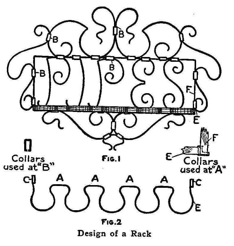
Design of a Rack
Strips of soft iron, 1/4 or 3/16 in. in width and 1/32 in. thick,
are used in making the pipe rack shown in Fig. 1. This material
can be obtained from any local hardware dealer who carries bar
iron in stock.
Draw a full-size sketch of the design on paper, then run a string
over each part, which, when straightened out, will give the
length. The scrolls are bent with a pair of round-nose pliers.
These, with a pair of flat-nose pliers, are all the tools
necessary. The part for holding the pipes is shown in Fig. 2. The
end elevation, at E and F, shows how the rack is fastened to the
main frame of the rack.
Contributed by J. W. Vener, Boston, Mass.
To Clean Silver
A good method to clean silver of any kind is to place the
articles in an aluminum vessel and add a few pieces of zinc. Hot
water is added and the silver boiled until clean. It is best to
use soft water. The tarnish is removed by the electrolytic action
of the zinc on the aluminum and the silver, and the latter will
take on a bright luster. This method of cleaning will not injure
oxidized or black silver, nor that which is partly oxidized.
Sharpening Skates with a File
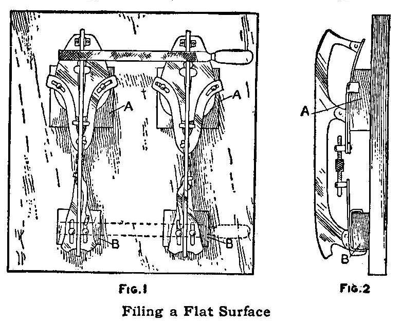
Filing a Flat Surface
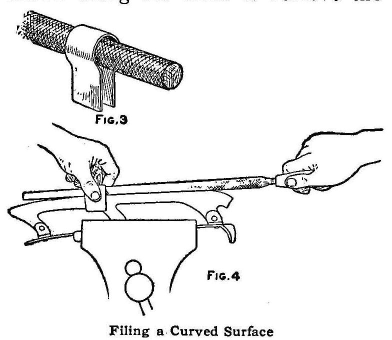
Filing a Curved Surface
Two methods are shown in the sketches for filing skates-one for
hollow filing and the other for filing flat and straight across
the blade. The method shown in Figs. 1 and 2 is for filing the
blade flat. The device for holding the skates consists of a board
on which four blocks, AA and BB, are nailed. These blocks are
fastened on the board in the relative positions of the heel and
sole on a shoe. The skates are clamped on them in the same manner
as on a shoe. A flat file is drawn across both blades of the
skates as shown. After the roundness is cut down on the edges of
the blades the skates are removed and the file is drawn along the
sides to remove the burr. Skates filed in this way have flat
surfaces with sharp edges.
Some skaters like a hollow-ground skate and the method shown in
Figs. 3 and 4 can be used for filing a slightly curved surface in
the blade. A piece of tin or sheet metal is shaped over a round
file as shown in Fig. 3. The manner of filing the curves is shown
in Fig. 4. The piece of metal is held over the file and blade of
the skate as the file is worked.
Lines and Letters Made with a Carpenter’s Pencil
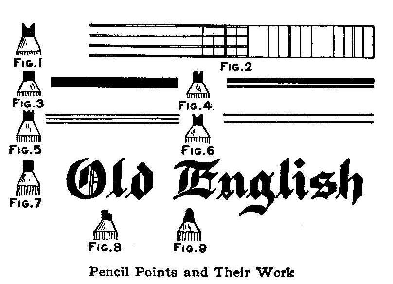
Pencil Points and Their Work
The sketch shows some unusual work made with a carpenter’s
pencil. If the flat lead is notched with a three-cornered file
(Fig. 1), two parallel lines may be drawn at one stroke, or
various rulings may be made, as shown in Fig. 2. Broad lines can
be made, as shown in Fig. 3, or unequal widths as in Fig. 4. In
Figs. 2, 5 and 6 are shown lines especially adapted for the
bookkeeper or draftsman. If one lacks the ability to draw old
English letters with a pen, the letters may be first drawn with a
carpenter’s pencil (Fig. 7) and the outlines marked with ink and
finally filled in. Narrow lines are made with points cut as in
Figs. 8 and 9. A little practice with the carpenter’s pencil in
making these letters will enable the student to finally produce
them with the pen used for the purpose.
Insulating Aluminum Wire
Aluminum wire plunged hot into a cold solution of carbonate of
soda becomes coated with a strong layer of oxide which forms an
excellent insulator to electricity.
How to Build an Ice-Yacht
Condensed from an article by H. Percy Ashley in Rudder.
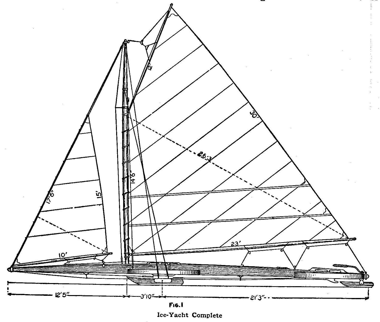
Ice-Yacht Complete
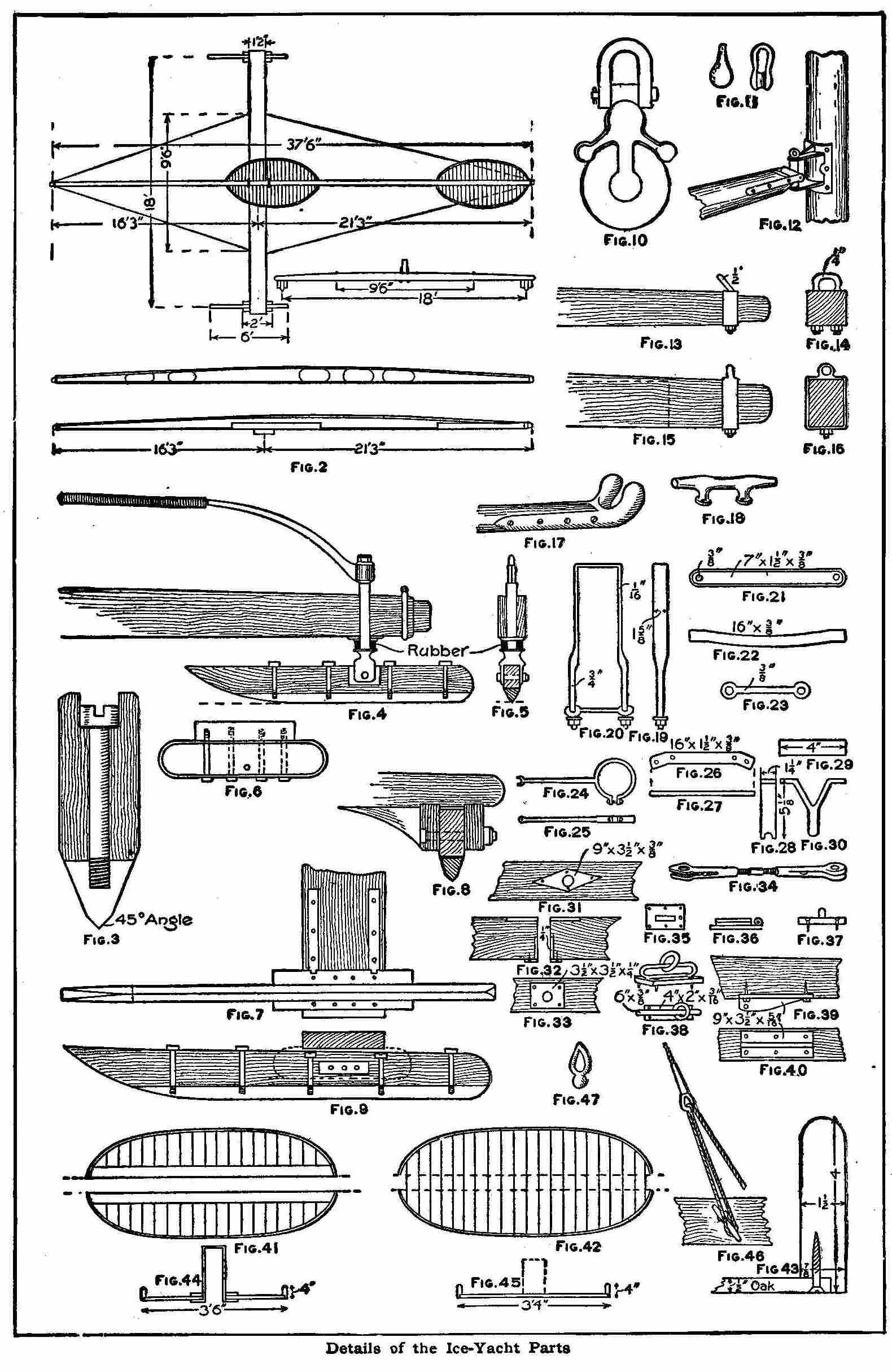
Details of the Ice-Yacht Parts
The plans and specifications shown in the illustrations are for
making a 400-ft. class ice-yacht, having a double cockpit to
accommodate four persons. The weight of the persons in the
forward cockpit keeps the boat from rearing when in a stiff
breeze. The forward cockpit can be removed if necessary.
The materials used are: backbone, white pine; center, clear
spruce; sides, white oak caps; runner plank, basswood, butternut
or oak; cockpit, oak; runners, chocks, etc., quartered white oak.
All the iron work should be first-grade Swedish iron, with the
exception of the runners, which are soft cast iron.
It is not necessary to go into detail with the measurements as
they are plainly shown in the sketches. The backbone is 37-1/2
ft. over all, 12 in. in the center, 5 in. stern, 3-1/2 in. at the
nose; width 4-1/2 in. All wood should be selected from the best
grades, well seasoned and free from checks. In Fig. 1 is shown
the complete ice-yacht with general dimensions for the sail and
main parts. Other dimensions are shown in Fig. 2. The backbone
is capped on the upper and lower edges full length with strips of
oak, 4-1/4 in. wide and 5/8 in. thick. The lengthwise side strips
of spruce are 1-1/4 in. thick. The filling-in pieces placed
between the side pieces are of seasoned white pine, leaving the
open places as shown in Fig. 2. The parts are put together with
hot glue and brass screws.
The runner plank should be placed with the heart of the wood up,
so as to give the natural curve from the ice so that it will act
as a spring. The plank is 16 in. wide in the center, 14 in. at
the ends; 4-1/8 in. thick at the center and 2-3/4 in. at the
ends.
Details of the runners are shown in Figs. 3, 4, 5, 6, 7, 8 and 9.
The cast iron shoes are filed and finished with emery paper,
making the angle on the cutting edge 45 deg. on both sides. The
runners are 7-1/4 in. wide over all and 2-1/8 in. thick. The soft
iron casting is 2-1/4 in. deep. The shoes are fastened by 5/8-in.
machine bolts. These are shown in Figs. 3 and 9. The rudder is
2-3/4 in. thick, 5 in. deep, including wood and iron, and 3 ft.
long. The cast iron shoe is 1-7/8 in. deep and fastened on with
four 1/2-in. machine bolts. A brass plate, 1/4 in. thick, 2 in.
wide and 7 in. long, is inserted on each side of the runners as
shown in Fig. 9. Three holes are drilled through for a 3/4-in.
riding bolt that can be shifted as desired for rough or smooth
ice. The runner chocks and guides are 1-7/8 in. thick and 4-1/2
in. deep. They are set in the runner plank 1/4 in. and fastened
with glue and 1/2-in. lag screws. These are shown in Figs. 6 and
7.
The aft cockpit is stationary, while the fore or passenger
cockpit can be removed at will. Both cockpits are the same size,
42 in. wide and 7 ft. long over all. Each one has a bent rail,
1-1/2 in. by 4 in., grooved 1/2 in. by 7/8 in. before bending.
The flooring is of oak, 1-1/2 in. thick and 4 in. wide,
tongue-and grooved. The forward cockpit is made in halves and
hung on the backbone with wrought-iron straps and bolts. These
are shown in Figs. 41, 43 and 44. Two pieces of oak, 1/2 in, by 4
in. are fastened with screws to the flooring, parallel with the
backbone in the forward cockpit. The runner plank which passes
under this cockpit gives it stability.
The spars should be hollow and have the following dimensions:
Mast, 23 ft. 3 in.; heel, 3-3/4 in.; center, 5-1/4 in.; tip, 4
in.; boom 23-1/2 ft.; heel, 3-3/4 in.; center, 4 in.; tip,
2-7/8 in. at ends; gaff, 12-1/2 ft.; center, 3-1/2 in.; ends,
2-1/2 in.; jib-boom, 10-1/2 ft.; 1-3/4 in. at the ends, 2-1/8
in. at the center. The gaff is furnished with bent jaws of oak,
Fig. 17, and the main boom with gooseneck, Fig. 12.
Galvanized cast-steel yacht rigging, 5/16 in. in diameter, is
used for the shrouds; jibstay, 3/8 in. in diameter; runner plank
guys, 5/16 in. in diameter; bobstay, 3/8 in. in diameter;
martingale stay, 1/4 in. in diameter. The throat and peak
halyards are 3/8 in. in diameter; jib halyards, 1/4 in. in
diameter.
The main sheet rigging is 9/16-in. Russian bolt rope; jibs,
7/16-in. manila bolt rope, 4-strand; jib-sheet, 3/8-in. manila
bolt rope. Four 1/2-in. bronze turnbuckles, Fig. 34, are used for
the shrouds; one 5/8-in. turnbuckle for the jibstay and one for
the bobstay; four 3/8-in. turnbuckles for the runner plank stays,
and one for the martingale stay.
Two rope blocks for 3/8-in. wire rope, Fig. 10, are used for the
peak and throat, and one block for the wire rope 1/4 in. in
diameter for the jib halyard. Four 6-in. and one 7-in. cleats,
Fig. 18, are used. The blocks shown in Fig. 11 are used for the
main and jib sheets. The steering arrangement is shown in Figs. 4
and 5. The tiller is 3-1/2 ft. long; rudder post, 1-1/4 in. in
diameter; shoulder to lower end of jaws, 4 in.; depth of jaws,
2-7/8 in.; length of post including screw top, 12 in. The rubber
washer acts as a spring on rough ice.
In Figs. 13, 14, 15 and 16 are shown metal bands for the nose of
the backbone, and Figs. 19, 20, 21, 22 and 23 show the saddles
that fit over the backbone and hold the runner plank in place.
There are two sets of these. A chock should be sunk in the runner
plank at each side to connect with the backbone to keep it from
slipping sidewise as the boat rises in the air. The martingale
spreader is shown in Figs. 24 and 25. Straps through which the
ring bolts for the shrouds pass on the ends to fasten the
turnbuckles for the runner plank guys are shown in Figs. 26 and
27. The bobstay spreaders are shown in Figs. 28, 29 and 30. In
Fig. 31 is shown the top plate for the rudder post and in Figs.
32 and 33, the lower plate for same. The mast step is shown in
Figs. 35, 36 and 37. Two positions of the jib traveler are shown
in Fig. 38. The anchor plate for the bobstay under the cockpit is
shown in Figs. 39 and 40.
At the nose and heel the runner plank guys end in a loop. The
bobstay has a loop at the nose and ends in a turnbuckle that
fastens to the anchor plate under the cockpit, aft. The shrouds,
jibstay and martingale have loops at the masthead and are spliced
bare over solid thimbles. The loops are finished in pigskin and
served with soft cotton twine over the splice and varnished. The
parceling is done with insulating tape. Serve the tiller with
soft cotton twine and ride a second serving over the first. For
the halyards hoisting use a jig shown in Fig. 46. The thimble
shown in Fig. 47 is made by splicing the rope to the thimble at
running part of halyard and passing back and forth through cleat
and thimble. This gives a quick and strong purchase and does away
with cumbersome blocks of the old-fashioned jig. The jib-sheet
leads aft to the steering cockpit. The main-sheet ends in a jig
of a single block and a single block with becket. Be sure that
your sail covers are large enough—the sail maker always makes
them too tight. The cockpit covers must fit tightly around the
cockpit rail. Many boats have sail and cockpit covers in one
piece.
The woodwork may be finished as desired by the builder. The
dimensions of the sails are given in the general drawing, Fig. 1.
Turning Lights On and Off from Any Number of Places
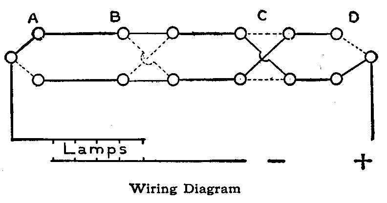
Wiring Diagram
This can be done by the use of any number of reversing switches
such as those shown at B and C. These are inserted between the
two-way switches A and D. Turning such a switch up or down
connects the four contact pieces either diagonally as at C, or
lengthwise as at B. The diagram shows connection from A to D,
when the lamps will be on, but by turning either of these four
switches into its alternative position, shown by the dotted
lines, the circuit will be broken and the lights extinguished.
When this has been done, the circuit may be restored and the
lamps lighted again by altering either of the four switches in
exactly the same way, and so on.
It will be observed that a reversing switch used in this way
practically undoes whatever is done by the other switches. In the
accompanying diagram only two reversing switches are shown and
the lights can be independently controlled from four distinct
positions. Any number of reversing switches can be placed between
the two-way switches A and D to increase the number of places
from which the lights could be turned on and off.
Contributed by J. S. Dow, Mayfield, London.
How to Make an Electric Pendant Switch
It is often desired to use a pendant switch for controlling
clusters of incandescent lamps. When such a switch is not at
hand, a very good substitute can be made by screwing a common
fuse plug into a key socket and connecting the socket in series
with the lamps to be controlled. In this way you get a safe,
reliable, fused switch.
Contributed by C. C. Heyder, Hansford, W. Va.
Measure
Never guess the length of a piece of work—measure it.
Home-Made Water Motor
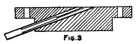
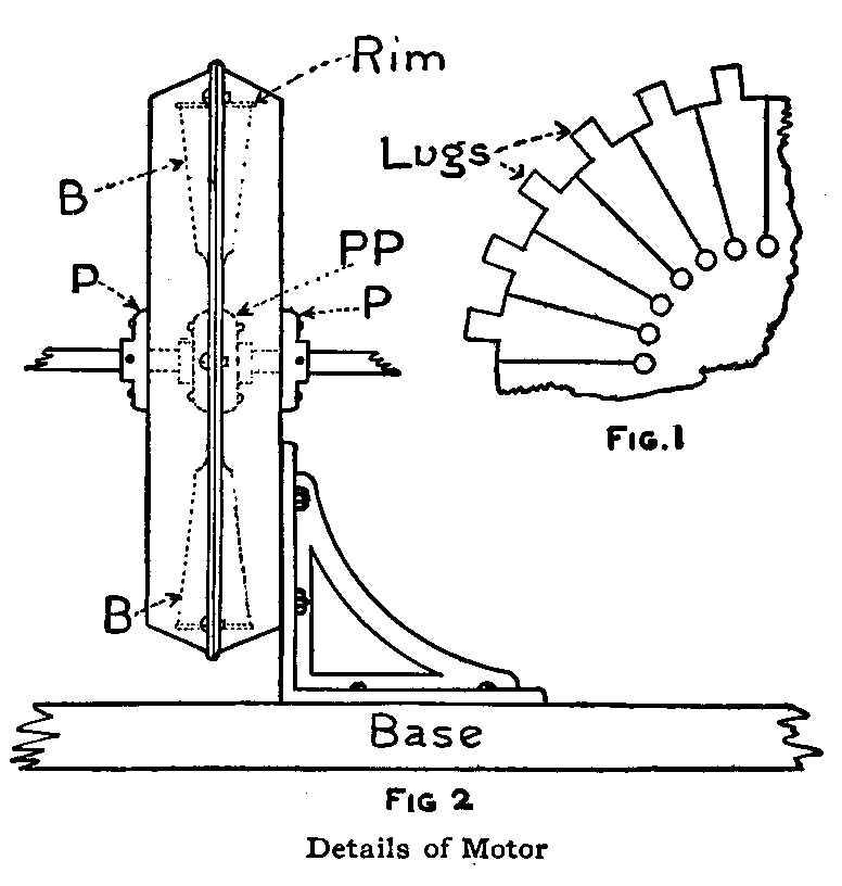
Details of Motor
The small water motor shown in the illustration is constructed in
the same manner as a German toy steam turbine. The wheel, which
is made of aluminum 1/16 in. thick and 7 in. in diameter, has 24
blades attached to it.
The lugs or extensions carrying the rim must be made from the
metal of the wheel, therefore a circle 8 in. in diameter must be
first described on the aluminum plate, then another circle 7 in.
in diameter within the first and then a circle for the base of
the blades, 3-1/2 in. in diameter. Twenty-four radial lines at
equal distances apart are drawn between the two smaller circles
and a 1/4-in. hole drilled at the intersecting points of the
radial lines and the innermost circle.
Centrally between each pair of radial lines and between the two
outer circles, 1/2 by 3/8-in. lugs are marked out and the metal
cut away as shown in Fig. 1. A 1/8-in. hole is then drilled in
the center of each lug. Each division is separated by cutting
down each radial line to the 1/4-in. hole with a hacksaw. Each
arm is then given a quarter turn, as shown by the dotted lines in
Fig. 2, and the lug bent over at right angles to receive the rim.
The rim is made of the same material as the disk and contains
twenty-four 1/8 in. holes corresponding to those in the lugs to
receive brass bolts 1/4-in. long.
The disks PP were taken from the ends of a discarded typewriter
platen, but if these cannot be readily obtained, they can be
turned from metal or a heavy flat disk used instead.
The casing was made from two aluminum cake pans whose diameter
was 8 in. at the base, increasing to 9 in. at the rim. The
centers of these were located and a 1/4 in. hole drilled for the
shaft. The disks P are the same as used on the wheel. Six holes
1/8-in. in diameter were drilled through the flat part of the
rims while the two halves were held together in a vise. Bolts
were placed through these holes to join the casing when ready for
assembling. One side of the casing was then bolted to two 4-in.
ordinary metal shelf brackets which were screwed to a substantial
wood base. This kept one-half of the casing independent of the
main structure so that the wheel is easily accessible.
The nozzle was made of 1/2-in. brass pipe which was first filled
with molten babbitt metal. When the metal was cool, a 1/4-in.
hole was drilled halfway through the length of the tube, the hole
being continued through to the other end by means of a 1/8-in.
drill. The lower orifice was then slightly enlarged with a small
taper reamer, and the upper portion of the bore was reamed out
almost to the brass to make a smooth entrance for the water.
A fixture to hold this nozzle is shown in Fig. 3. It was cast of
babbitt metal in a wood mold. The hole for the nozzle was drilled
at an angle of 20 deg. to the plate part. An alternative and
perhaps easier way would be to insert the nozzle in the mold at
the proper angle and cast the metal around it. A hole was then
cut in one of the sides of the casing at a point 2-7/8 in. along
a horizontal line from the center. The nozzle fixture was then
bolted on with the exit orifice of the nozzle pointing downward
and through the hole in the casing.
Six 1/8-in. holes were drilled through the flat portions of the
rims while the two halves of the casing were held securely
together in a vise. Bolts were used in these holes to join the
casing. The wheel was used on the dripboard of a kitchen sink and
no provision was made to carry off the spent water except to cut
two 1/2-in. holes in the bottom of the casing and allowing the
waste to flow off directly into the sink.
Contributed by Harry F. Lowe, Washington, D. C.
Device for Baseball Throwing Practice
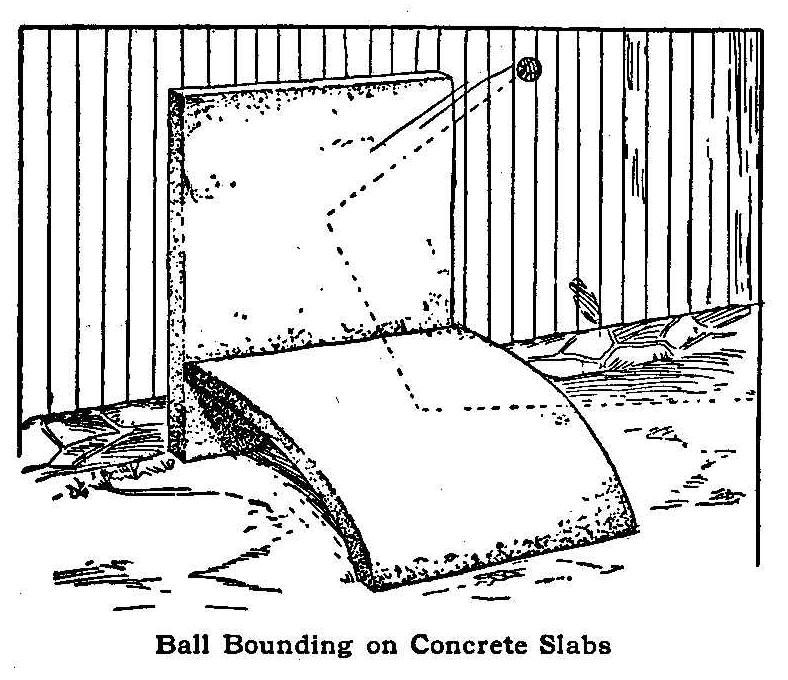
Ball Bounding on Concrete Slabs
Anyone training to be a baseball player will find the device
shown in the accompanying illustration a great help when
practicing alone. It consists of two cement slabs, one flat and
upright, the other curved and on the ground. The vertical slab is
fastened securely against a fence, barn or shed. The barn or the
shed is preferable, for if the slab is fastened to a fence, the
ball will bound over a great many times and much time will be
lost in finding it.
The player stands as far as he cares from the slabs and throws
the ball against the lower slab. The ball immediately rebounds to
the upright slab and returns with almost as great a force as it
was delivered. If the thrower does not throw the ball exactly in
the same spot each time, the ball will not rebound to the same
place, consequently the eye and muscles are trained to act
quickly, especially if the player stands within 15 or 20 ft. of
the slabs and throws the ball with great force.
This apparatus also teaches a person to throw accurately, as a
difference in aim of a few inches on the lower slab may cause the
ball to flyaway over the player’s head on the rebound.
Contributed by F. L. Oilar, La Fayette, Indiana.
How to Mail Photographs
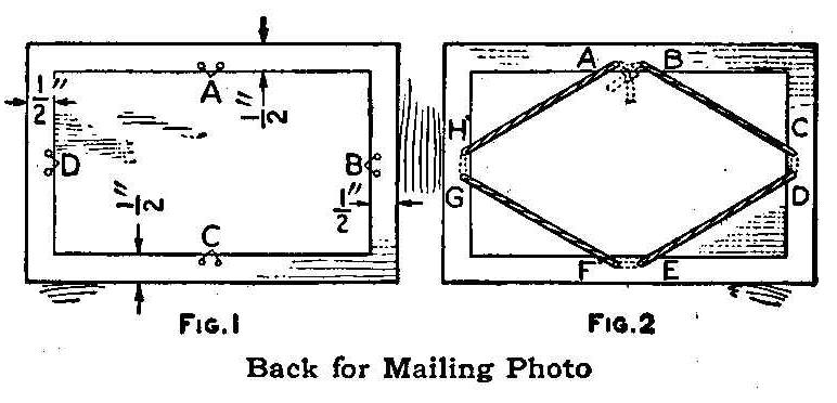
Back for Mailing Photo
Cut a piece of cardboard 1 in. longer and 1 in. wider than the
mount of the photograph and lay the picture on it in the center.
This allows a 1/2-in. border on all sides of the photograph.
Punch two holes 1 in. apart at A, B, C and D, Fig. 1, in the
cardboard border close to the edge of the picture. Put a string
up through the hole B, Fig. 2, then across the corner of the
photograph and down through the hole C and up through hole D,
then to E, etc., until the starting point A is reached, and tie
the ends.
The photograph will not get damaged, if it is covered with tissue
paper and placed with the face to the cardboard. The extension
border of cardboard prevents the edges of the mount from being
damaged and the corners from wearing. Both cardboard and
photograph are wrapped together in paper, and the package is
ready for mailing.
Contributed by Earl R. Hastings, Corinth, Vt.
A Mystifying Watch Trick
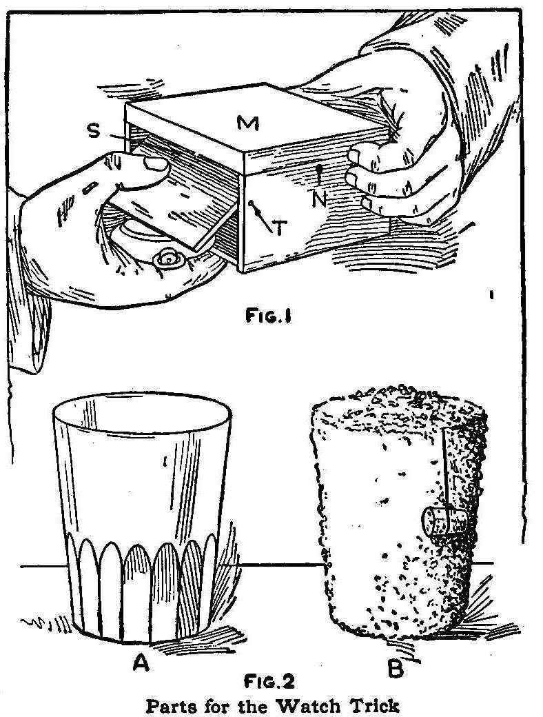
Parts for the Watch Trick
Borrow a watch from one of the audience and allow the owner to
place it in the box, as shown in Fig. 1. This box should be about
3 in. long, 4 in. wide and 2-1/2 in. deep, says the Scientific
American. It should be provided with a hinged cover, M, with a
lock, N. The tricky part of this box is the side S, which is
pivoted at T by driving two short nails into it, one through the
front side and the other through the back, so that when S is
pushed in at the top, it swings around as shown in Fig. 1 and
allows the watch to slide out into the performer’s hand. The side
S should fit tightly when closed, so that the box may be examined
without betraying the secret. As the side S extends down to the
bottom of the box, it facilitates the use of the fingers in
pulling outward at the lower pan while the thumb is pressing
inward at the top part. The side of the box opposite S should be
built up in the same way, but not pivoted.
Use a flat-bottom tumbler, A, Fig. 2, containing an inner cone,
B, for the reproduction of the watch. The cone is made of
cardboard pasted together so it fits snugly inside of the
tumbler. The cone is closed except at the bottom, then bran is
pasted on the outside surfaces to make the tumbler appear as if
filled with bran when it is in place. Place the tumbler with the
cone inside on a table somewhat in the background. Put some loose
bran on top of the cone and allow the cork, attached as shown in
B, Fig. 2, to hang down on the outside of the tumbler, away from
the audience. A large handkerchief should be laid beside the
tumbler.
After the watch has been placed in the box, Fig. 1, the performer
takes the box in his left hand, and while in the act of locking
it with his right hand secures possession of the watch as
previously explained. Tossing the key to the owner of the watch,
the performer places the box on a chair or table near the
audience and, with the watch securely palmed, walks back to get
the tumbler. Standing directly in front of the tumbler with his
back toward the audience, the performer quickly raises the cone
with his right hand, lays the watch in the bottom of the tumbler
and replaces the cone.
The loaded tumbler and the handkerchief are then brought forward,
and the former is placed in full view of the audience with the
cork hanging down behind it. The performer calls attention to the
tumbler being full of bran and picks up some of it from the top
to substantiate his statement. He then spreads the handkerchief
over the tumbler, commands the watch to pass from the box into
the tumbler and the bran to disappear.
The box is then handed to the owner of the watch so that he may
unlock it with the key he holds. As soon as the box is found to
be empty, the performer grasps the handkerchief spread over the
tumbler, also the cork tied to the cone. Raising the
handkerchief, he carries up the cone within it, leaving the watch
in the bottom to be returned to its owner.
Locking Several Drawers with One Lock
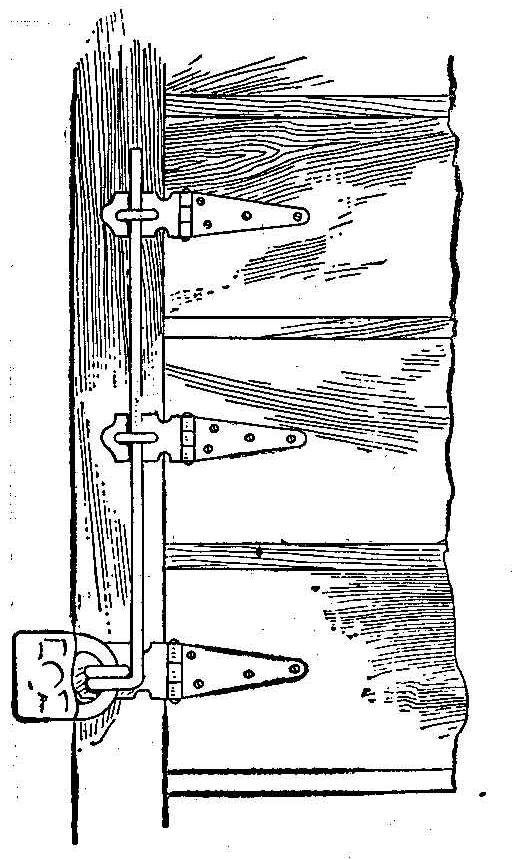
A series or row of drawers can be secured with one lock by using
the device shown in the sketch. This method takes away several
dangling locks and the carrying of many keys. A rod is used
through the various staples over the hasps. The rod is upset on
one end and flattened to make sufficient metal for drilling a
hole large enough to insert the bar of a padlock. If the bar is
made of steel and hardened, it is almost impossible to cut it in
two.
Contributed by F. W. Bentley, Huron, S. Dak.
Testing Small Electric Lamps
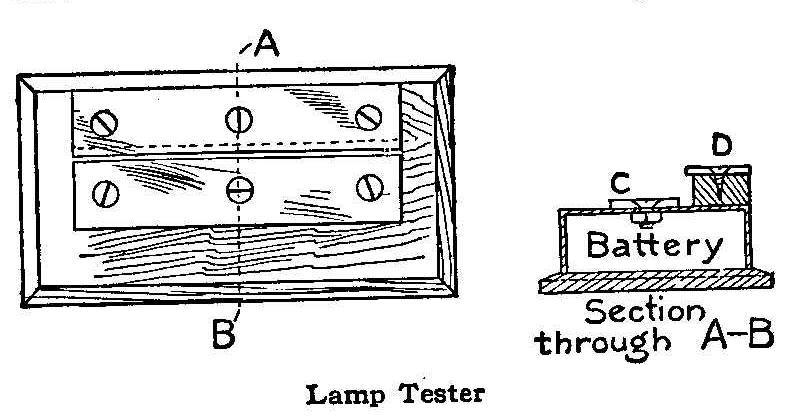
Lamp Tester
The accompanying sketch shows the construction of a handy device
for testing miniature electric lights. The base is made to take
in an electric flash lamp battery. Two strips of brass, C and D,
are connected to the battery. The lamp is tested by putting the
metal end on the lower brass strip and the side against the upper
one. A great number of lamps can be tested in a short time by
means of this device.
Contributed by Abner B. Shaw, North Dartmouth, Mass.
How to Make a Pin Ball
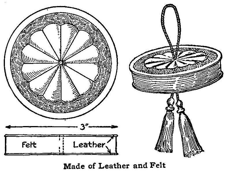
Made of Leather and Felt
The pin ball shown in the illustration is made of calfskin
modeling leather and saddler’s felt. Two pieces of leather are
used, and one piece of felt, all three being cut circular to a
diameter of about 3 in. The felt may be about 1/2 in. thick, and
leather of a deep brown color is recommended.
Moisten the leather on the back side with as much water as it
will take without showing through the face. Lay it on a sheet of
heavy glass or copper, or other hard, smooth, nonabsorbent
material. Place the design, which has been previously prepared,
over the face of the leather. Indent the outline of the design
with a nutpick or any other pointed tool that will not cut the
leather. Remove the pattern, and go over the outline again to
deepen the tool marks.
The space between the border and the design is now stamped with a
cup-pointed nail set, care being taken not to cut the leather,
especially if the tool be new. Rubbing the edges of the nail set
over a piece of emery paper will serve to dull them, if they are
too sharp.
When the designs have been worked on the leather, paste or glue
the leather to the two sides of the belt, and punch a hole in the
center through which to place a cord for hanging up the ball.
Cleaning Woodwork
An easy method of removing the dirt and old varnish at the same
time around a kitchen sink is told by a correspondent of National
Magazine as follows:
Make a soft soap from common yellow laundry soap, and when it is
almost cold stir in one tablespoonful of concentrated
lye and
one-half cupful of kerosene. When the mixture becomes a heavy
paste, it is ready to be spread over the woodwork with a paint
brush. Allow the soap to remain for a day and a half, then wash
it off with plenty of hot water. The woodwork will be clean and
ready for varnishing when it dries out.
Bill File Made of Corkscrews
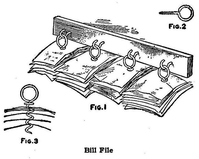
Bill File
An ordinary corkscrew makes a convenient file for small bills or
memoranda. It may be thrown in any position without danger of the
papers slipping off. A rack to hold a number of files can be made
of a wood strip (Fig. 1) fitted with hooks or screw eyes cut in a
hook shape, as shown in Fig. 2, Single bills may be separated
from the others and will remain separated as in Fig. 3.
Contributed by James M. Kane, Doylestown, Pa.
Ornamental Metal Inkstand
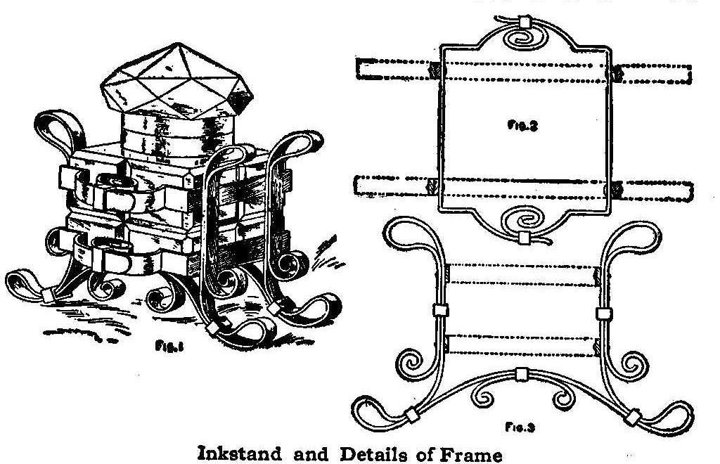
Inkstand and Details of Frame
The metal required for making this stand is 3/16 in. in width and
may be steel, brass or copper. The shaping is done as shown in
Figs. 2 and 3. There are, in all, eight pieces to be bent. The
two supports are each formed of one piece of metal with the
exception that the end scroll pieces on the under side are made
separately. Eight rivets are required to fasten the two
horizontal rings to the supports. The glass receptacle can be
purchased at a stationery store.
Holding Eyeglasses Firm
Persons who wear noseglasses and who are troubled with excessive
perspiration, should chalk the sides of the bridge of the nose
before putting on the glasses. The latter will then never slip,
even in the warmest weather. If the chalk shows, use a pink
stick, which can be purchased from any art school or supply
store.
Substitute for Gummed Paper
Gummed paper is a great convenience in the home especially for
labels, but it is not always found among the household supplies.
The gummed portions of unsealed envelopes in which circulars are
received can be utilized for this purpose. Quite a large label
may be made from these envelope flaps.
Repairing a Broken Phonograph Spring
As I live a great distance from a railroad station, I did not
care to pay the price, and await the time necessary to deliver a
new phonograph spring to replace one that broke in my machine,
and I repaired the old one in a creditable manner as follows:
I forced the two ends of the break out where I could get at them,
then heated each end separately with a pair of red hot tongs and
turned a hook or lap on them the same as the joints in knock-down
stovepipes. When the ends were hooked together, the spring worked
as good as new. The heated portion did not affect the strength of
the spring.
Contributed by Marion P. Wheeler, Greenleaf, Oregon.
Calls While You Are Out
If you wish to know whether or not the door or telephone bell
rings during your absence, place a little rider of paper or
cardboard on the clapper in such a way that it will be dislodged
if the bell rings.
A Small Bench Lathe Made of Pipe Fittings
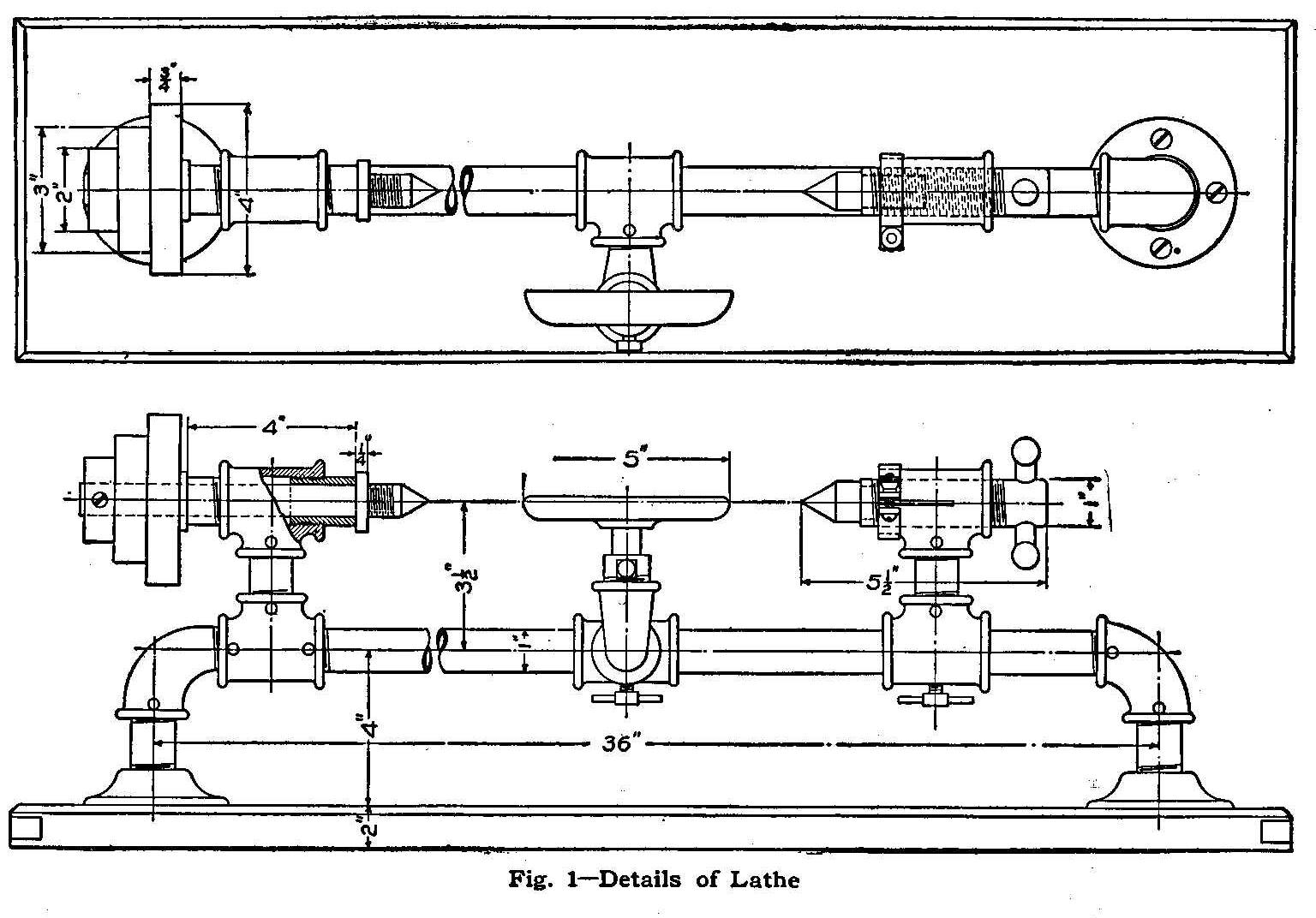
Fig. 1-Details of Lathe
The most important machine in use in the modern machine or
wood-working shop is the lathe. The uses to which this wonderful
machine can be put would be too numerous to describe, but there
is hardly a mechanical operation in which the turning lathe does
not figure. For this reason every amateur mechanic and
wood-worker who has a workshop, no matter how small, is anxious
to possess a lathe of some sort. A good and substantial homemade
lathe, which is suitable for woodturning and light metal work,
may be constructed from pipe and pipe fittings as shown in the
accompanying sketch.
The bed of this lathe is made of a piece of 1-in. pipe, about 30
in. long. It can be made longer or shorter, but if it is made
much longer, a larger size of pipe should be used. The headstock
is made of two tees, joined by a standard long nipple as shown in
Fig. 1. All the joints should be screwed up tight and then
fastened with 3/16-in. pins to keep them from turning. The ends
of the bed are fixed to the baseboard by means of elbows, nipples
and flanges arranged as shown. The two bearings in the headstock
are of brass. The spindle hole should be drilled and reamed after
they are screwed in place in the tee. The spindle should be of
steel and long enough to reach through the bearing and pulley and
have enough end left for the center point. The point should
extend about 1-1/2 in. out from the collar. The collar can be
turned or shrunk on the spindle as desired. The end of the
spindle should be threaded to receive a chuck.
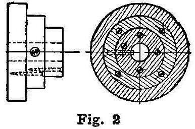
Fig. 2
The tailstock is also made of two tees joined by a nipple. The
lower tee should be bored out for a sliding fit on the bed pipe.
The upper one should be tapped with a machine tap for the spindle
which is threaded to fit it. The spindle has a handle fitted at
one end and has the other end bored out for the tail stock
center. Both the tail stock and the headstock centerpoints should
be hardened. A clamp for holding the tail stock spindle is made
of a piece of strap iron, bent and drilled as shown. It is held
together by means of a small machine screw and a knurled nut. The
tee should have a slot cut in it about one-half its length and it
should also have one bead filed away so that the clamp will fit
tightly over it.
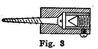
Fig. 3
The hand rest is made from a tapering elbow, a tee and a forging.
The forging can be made by a blacksmith at a small expense. Both
the lower tees of the handrest and the tailstock should be
provided with screw clamps to hold them in place.
The pulley is made of hardwood pieces, 3/4 or 1 in. thick as
desired. It is fastened to the spindle by means of a screw, as
shown in Fig. 2, or a key can be used as well.
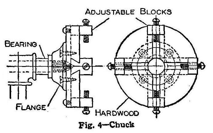
Fig. 4-Chuck
Care must be taken to get the tailstock center vertically over
the bed, else taper turning will result. To do this, a straight
line should be scratched on the top of the bed pipe, and when the
tail stock is set exactly vertical, a corresponding line made on
this. This will save a great deal of time and trouble and
possibly some errors.
The two designs of chucks shown in Figs. 3 and 4 are very easy to
make, and will answer for a great variety of work.
As the details are clearly shown and the general dimensions given
on the accompanying sketches, it should not be a difficult matter
for the young mechanic to construct this machine.
Contributed by W. M. Held, Laporte, Indiana.
Holder for Flexible Lamp-Cord
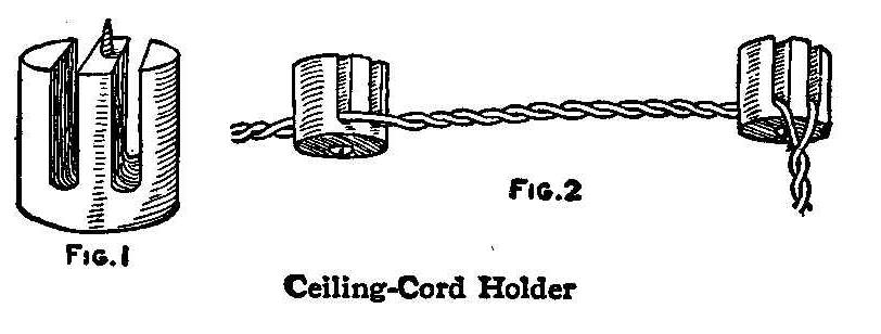
Ceiling-Cord Holder
The holder is made of a round stick—a piece of a broom handle
will do—as shown in Fig. 1. It is about 1 in. long with two
notches cut out for the strands of the cord. These holders are
easily made and will answer the purpose almost as well as the
ones made in porcelain. Painting or enameling will improve not
only their appearance, but also their insulating properties.
Several of them can be used along a line, as shown in Fig. 2.
Contributed by M. Musgrove, Boissevain, Man.
Support for Double Clotheslines
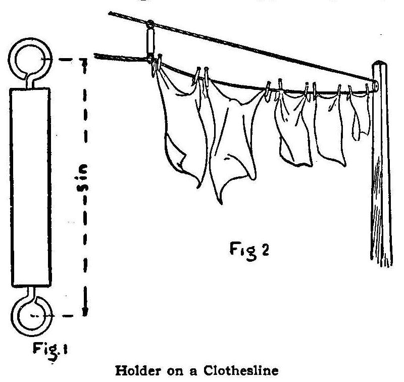
Holder on a Clothesline
Anyone using a double clothesline over pulleys will find the
arrangement shown in Fig. 1 for supporting the lower line quite
convenient. The support is made of a piece of 3/4-in. square or
round wood which has a screw-eye turned into each end. The line
is run through these screw-eyes as shown in Fig. 2.
Contributed by W. W. UpDeGraff, Fruitvale, Cal.
Hot Pan or Plate Lifter
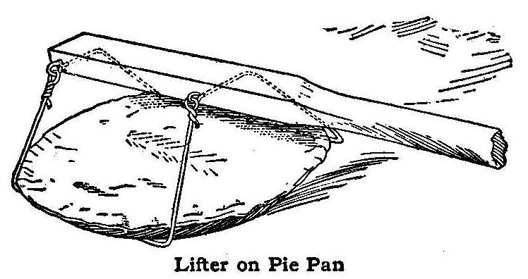
Lifter on Pie Pan
Unless a person uses considerable caution, bad burns may be
suffered when taking hot pies from an oven. If one reaches in and
takes hold of the pie pan with a cloth, the arm is liable to
touch the oven door and receive a burn. To obviate this, I made
the device shown in the sketch for lifting hot pie pans and
plates. The handle is of pine about 18 in. long, and the two
loops are made of heavy wire. The ends of the first loop of wire
are put through the handle from the back, as shown, and then bent
so as to stand out at an angle. The second loop is hinged to
swing free on the opposite side of the handle. In use, the hinged
side of the loop is dropped under one edge of a plate or pan and
the rigid loop is then hooked under the opposite side. The weight
of the pan or dish draws the loops together and there is little
or no danger of a spill. The same lifter will pick up any size of
plate or pan from a saucer to the largest pie
plates.
Contributed by E. J. Cline, Ft. Smith, Ark.
Weighting Indian Clubs
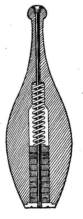
An ordinary Indian club can be fixed so that different weights
may be had without changing clubs. Each club is bored to receive
lead washers which are held in place
by a spiral spring. A bolt is run through from the handle end and
fastened with a round nut. The lead
washers and spring slip over the bolt as shown in the
illustration. Changing the number of washers changes the weight
of the club.
Contributed by Walter W. White, Denver, Colo.
Venting a Funnel
When using a tight-fitting funnel in a small-neck bottle, trouble
is usually experienced by the air causing a spill. This can be
easily remedied by splitting a match in half and tying the parts
on the sides of the stem with thread.
Contributed by Maurice Baudier, New Orleans, La.
Lubricating Woodscrews
A screw may be turned into hardwood easily, by boring a small
hole and lubricating the screw threads with soft soap.
To Make “Centering” Unnecessary
For drilling a hole in a chucked piece, centering is just one
operation too many, if this method is followed: First, face off
the end of the piece, making a true spot at least as big as the
diameter of the drill. Put a center punch mark where the tool
lines indicate the center of revolution. This serves as a rough
guide for placing the drill between the tail stock center and the
work as usual. Clamp a tool in the tool-post and, on starting the
lathe, bring it in contact with the drill and keep it firmly so
until the drill is in fully up to the lips. This prevents the
drill from wobbling, and when once in true up to its size, it
cannot change any more than under any other starting conditions.
After being entered, the drill does not need the tool, which
should be backed out of contact.
Fountain Pen Cap Used as a Ruler
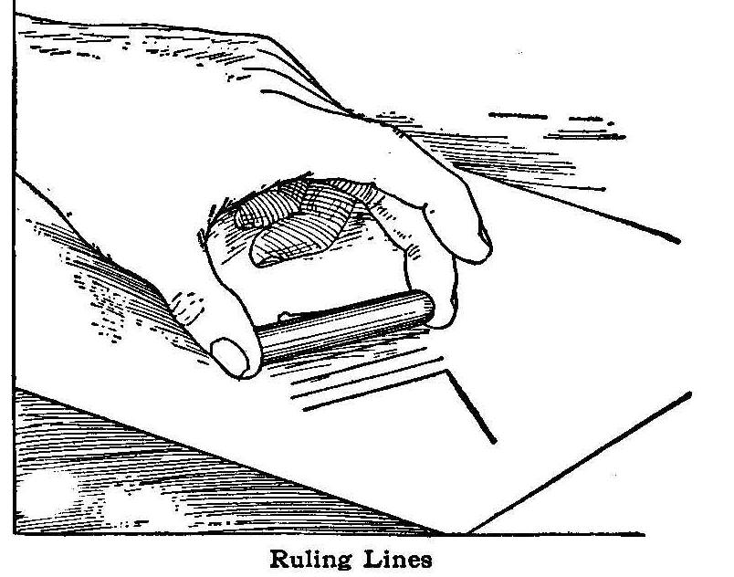
Ruling Lines
When it is necessary to draw a short line and there is no ruler
at hand, take off the cap of your fountain pen and use it as a
ruler. If the cap is fitted with a retaining clip, all the
better, as this will prove a safeguard against slipping.
Vanishing Handkerchief Trick
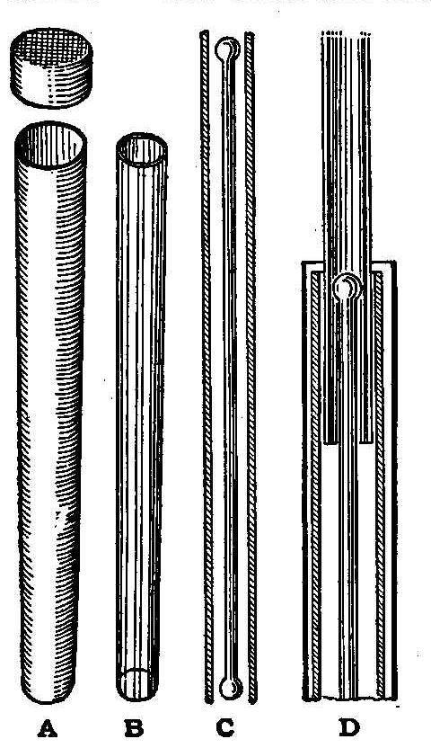
The necessary articles used in performing this trick are the
handkerchief, vanishing wand, a long piece of glass tubing, about
1/2 in. shorter than the wand, and a paper tube closed at
one end and covered with a cap at the other, says the Sphinx. The
handkerchief rod, shown at C, is concealed in the paper tube A
before the performance. The glass tube B, after being shown
empty; is put into the paper tube A, so that the handkerchief rod
now is within it, unknown to the spectators. The handkerchief is
then placed over the opening of the tube and pushed in by means
of the wand. In doing this, the handkerchief and the rod are
pushed into the wand, as shown in D. After the wand is removed,
the cap is placed over the paper tube, and this given to someone
to hold. The command for the handkerchief to vanish is given, and
it is found to be gone when the glass tube is taken out of the
paper cover. This is a novel way of making a handkerchief vanish.
It can be used in a great number of tricks, and can be varied to
suit the performer.
Removing Glass Letters from Windows
Glass letters are removed in the same way as metal letters, by
applying caustic soda or potash around the edges of the letters.
As the cement softens, manipulate the point of a pocket knife
under the edges of the letter until the caustic works completely
under and makes it easy to lift the letters. With care and
patience, every letter may be thus taken off without breakage.
A Guitar That Is Easy to Make
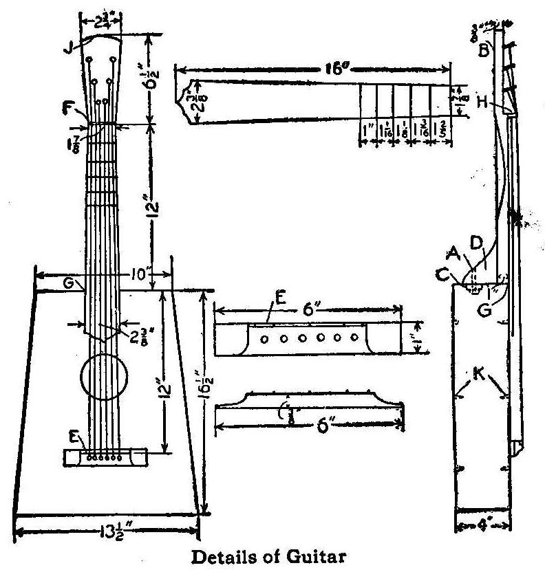
Details of Guitar
A guitar having straight lines, giving it an old-fashioned
appearance, can be made by the home mechanic, and if care is
taken in selecting the material, and having it thoroughly
seasoned, the finished instrument will have a fine tone. The
sides, ends and bottom are made of hard wood, preferably hard
maple, and the top should be made of a thoroughly seasoned piece
of soft pine. The dimensioned pieces required are as follows:
1 Top. 3/16. by 14 by 17 in.
1 Bottom. 3/16 by 14 by 17 in.
2 Sides. 3/16 by 3-5/8 by 16-3/4 in.
1, End. 3/16 by 3-5/8 by 13-1/8 in.
1 End. 3/16 by 3-5/8 by 9-5/6 in.
1 Neck. 1 by 2-5/16 by 18-1/2 in.
1 Fingerboard 5/16 by 2-5/8 by 16 in.
Cut the fingerboard tapering and fasten pieces cut from hatpins
with small wire staples for frets. All dimensions for cutting and
setting are shown in the sketch. The neck is cut tapering from G
to F and from J to F, with the back side rounding. A drawknife is
the proper tool for shaping the neck. Cut a piece of hard wood,
1/4 in. square and 1-7/8 in. long, and glue it to the neck at F.
Glue the fingerboard to the neck and hold it secure with clamps
while the glue sets.
The brace at D is 1 in. thick, cut to any shape desired. The
sides are glued together and then the front is glued on them.
Place some heavy weights on top and give the glue time to dry.
Fasten pieces of soft wood in the corners for braces. Glue the
neck to the box, making it secure by the addition of a carriage
bolt at A. A small block C is glued to the end to reinforce it
for the bolt. Glue strips of soft wood, as shown by K, across the
front and back to strengthen them. The back is then glued on and
the outside smoothed with sandpaper.
Make the bottom bridge by using an old hatpin or wire of the same
size for E secured with pin staples. Glue the bridge on the top
at a place that will make the distance from the bridge F to the
bottom bridge E just 24 in. This dimension and those for the
frets should be made accurately. Six holes, 3/16 in. in
diameter, are drilled in the bottom bridge for pins. The turning
plugs B and strings can be purchased at any music store.
Contributed by J. H. Stoddard, Carbondale, Pa.
Greasing the Front Wheels of an Automobile
The front wheel bearings of an automobile can be greased without
removing the wheels in the following manner: Remove the hub caps
and fill them with heavy grease and then screw them in place.
Continue this operation until the grease is forced between all
the bearings and out through the small clearance on the opposite
side of the wheels. This should be done at least once every month
to keep bearings well lubricated and free from grit. Dirt cannot
enter a well filled bearing as easily as muddy water can enter a
dry bearing.
Contributed by Chas. E. Frary, Norwalk, O.
Removing Mold
Mold on wallpaper can be removed at once by applying a solution
of 1 part salicylic acid in 4 parts of 95% alcohol.
How To Make A Paper Boat
A Light Boat That Can Be Easily Carried
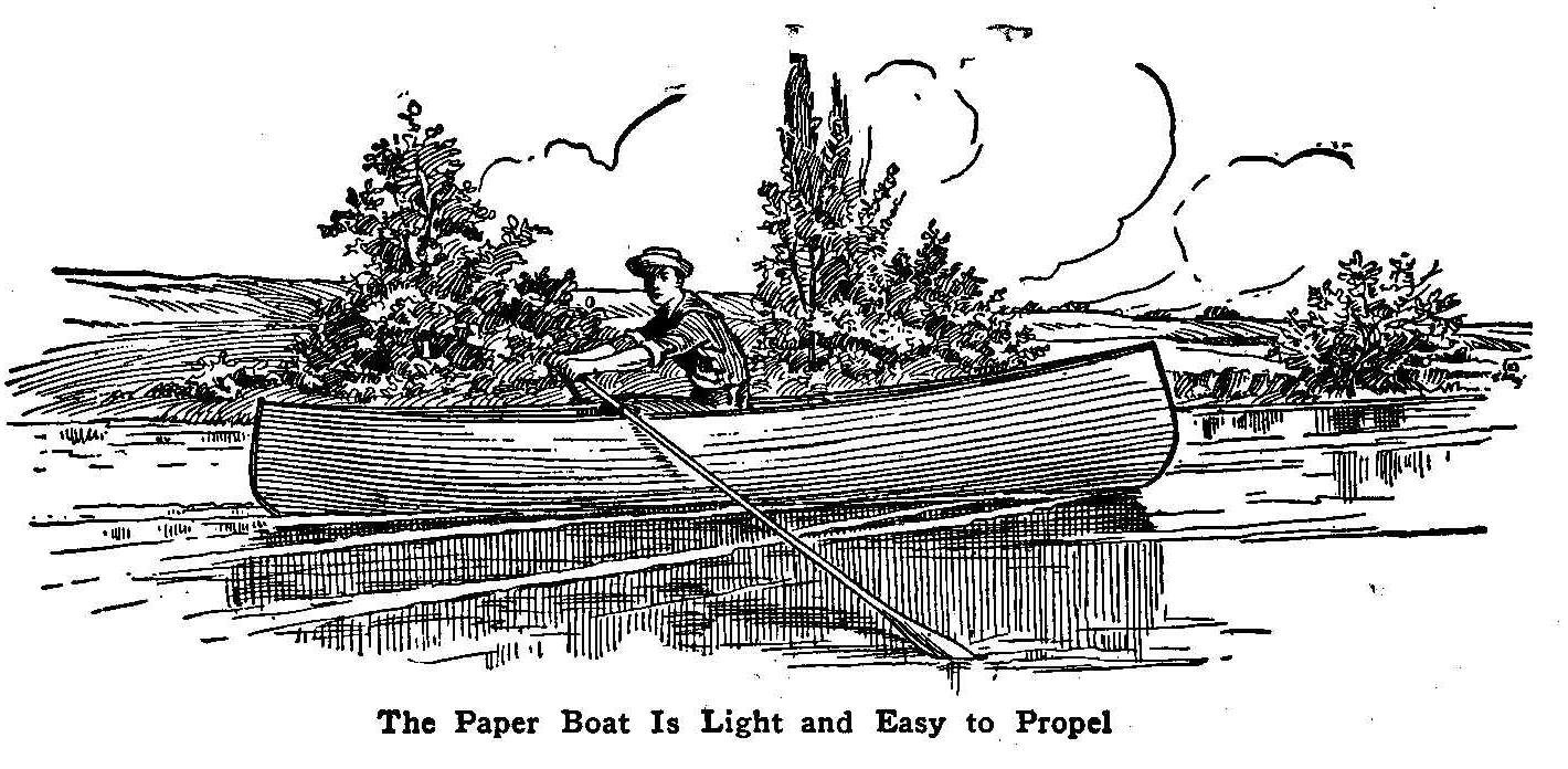
The Paper Boat Is Light and Easy to Propel
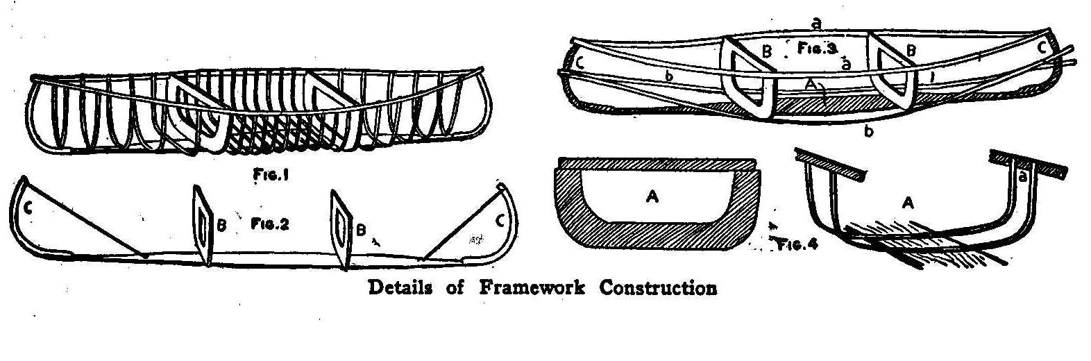
Detail of Framework Construction
Now you might think it absurd to advise making a paper boat, but
it is not, and you will find it in some respects and for some
purposes better than the wooden boat. When it is completed you
will have a canoe, probably equal to the Indian’s bark canoe. Not
only will it serve as an ideal fishing boat, but when you want to
combine hunting and fishing you can put your boat on your
shoulders and carry it from place to place wherever you want to
go and at the same time carry your gun in your hand. The material
used in its construction is inexpensive and can be purchased for
a few dollars.
Make a frame (Fig. 1) on which to stretch the paper. A board 1
in. thick and about 1 ft. wide and 11-1/2 ft. long is used for a
keel, or backbone, and is cut tapering for about a third of its
length, toward each end, and beveled on the outer edges (A, Fig.
2). The cross-boards (B, B, Fig. 2) are next sawed from a pine
board 1 in. thick. Shape these as shown by A, Fig. 4, 13 in. wide
by 26 in. long, and cut away in the center to avoid useless
weight. Fasten them cross-wise to the bottom board as shown in
Fig. 1 and 2, with long stout screws, so as to divide the keel
into three nearly equal parts. Then add the stem and stern pieces
(C, C, Fig. 2). These are better, probably, when made of green
elm. Screw the pieces to the bottom-board and bend them, as
shown in Fig. 2, by means of a string or wire, fastened to a nail
driven into the bottom. Any tough, light wood that is not easily
broken when bending will do. Green wood is preferable, because it
will retain the shape in which it has been bent better after
drying. For the gunwales (a, a, Fig. 3), procure at a carriage
factory, or other place, some tight strips of ash, 3/8 in. thick.
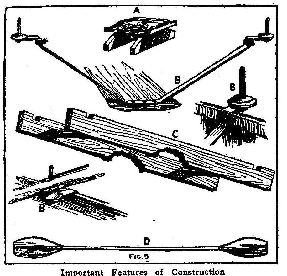
Important Features of Construction
Nail them to the crossboards and fasten to the end pieces (C, C,)
in notches, by several wrappings of annealed iron wire or copper
wire, as shown in Fig. 3. Copper wire is better because it is
less apt to rust. For fastening the gunwales to the crossboards
use nails instead of screws, because the nails are not apt to
loosen and come out. The ribs, which are easily made of long,
slender switches of osier willow, or similar material, are next
put in, but before doing this, two strips of wood (b, b, Fig. 3)
should be bent and placed as in Fig. 3. They are used only
temporarily as a guide in putting in the ribs, and are not
fastened, the elasticity of the wood being sufficient to cause
them to retain their position. The osiers may average a little
more than 1/2 in. in thickness and should be cut, stripped of
leaves and bark and put in place while green and fresh. They are
attached to the bottom by means of shingle nails driven through
holes previously made in them with an awl, and are then bent down
until they touch the strips of ash (b, b, Fig. 3), and finally
cut off even with the tops of the gunwales, and notched at the
end to receive them (B, Fig. 4). Between the cross-boards the
ribs are placed at intervals of 2 or 3 in., while in other parts
they are as much as 5 or 6 in. apart. The ribs having all been
fastened in place as described, the loose strips of ash (b, b,
Fig. 3) are withdrawn and the framework will appear somewhat as
in Fig. 1. In order to make all firm and to prevent the ribs from
changing position, as they are apt to do, buy some split cane or
rattan, such as is used for making chairbottoms, and, after
soaking it in water for a short time to render it soft and
pliable, wind it tightly around the gunwales and ribs where they
join, and also interweave it among the ribs in other places,
winding it about them and forming an irregular network over the
whole frame. Osiers probably make the best ribs, but twigs of
some other trees, such as hazel or birch, will answer nearly as
well. For the ribs near the middle of the boat, twigs 5 or 6 ft.
long are required. It is often quite difficult to get these of
sufficient thickness throughout, and so, in such cases, two twigs
may be used to make one rib, fastening the butts side by side on
the bottom-board, and the smaller ends to the gunwales, as before
described. In drying, the rattan becomes very tight and the twigs
hard and stiff.
The frame-work is now complete and ready to be covered. For this
purpose buy about 18 yd. of very strong wrapping-paper. It should
be smooth on the surface, and very tough, but neither stiff nor
very thick. Being made in long rolls, it can be obtained in
almost any length desired. If the paper be 1 yd. wide, it will
require about two breadths to reach around the frame in the
widest part. Cut enough of the roll to cover the frame and then
soak it for a few minutes in water. Then turn the frame upside
down and fasten the edges of the two strips of paper to it, by
lapping them carefully on the under side of the bottom-board and
tacking them to it so that the paper hangs down loosely on all
sides. The paper is then trimmed, lapped and doubled over as
smoothly as possible at the ends of the frame, and held in place
by means of small clamps. It should be drawn tight along the
edges, trimmed and doubled down over the gunwale, where it is
firmly held by slipping the strips of ash (b, b) just inside of
the gunwales into notches which should have been cut at the ends
of the cross-boards. The shrinkage caused by the drying will
stretch the paper tightly over the framework. When thoroughly
dry, varnish inside and out with asphaltum varnish thinned with
turpentine, and as soon as that has soaked in, apply a second
coat of the same varnish, but with less turpentine; and finally
cover the laps or joints of the paper with pieces of muslin stuck
on with thick varnish. Now remove the loose strips of ash and put
on another layer of paper, fastening it along the edge of the
boat by replacing the strips as before. When the paper is dry,
cover the laps with muslin as was done with the first covering.
Then varnish the whole outside of the boat several times until it
presents a smooth shining surface. Then take some of the split
rattan and, after wetting it, wind it firmly around both gunwales
and inside strip, passing it through small holes punched in the
paper just below the gunwale, until the inside and outside strips
are bound together into one strong gunwale. Then put a piece of
oil-cloth in the boat between the cross-boards, tacking it to the
bottom-board. This is done to protect the bottom of the boat.
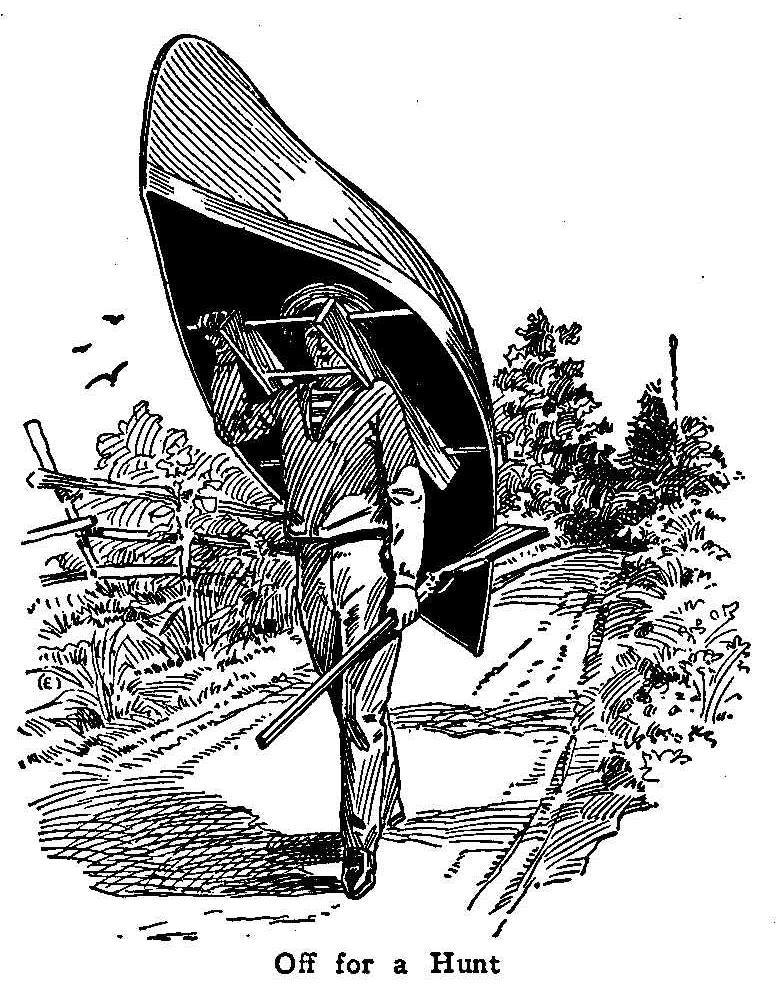
Off For Hunt
Now you may already have a canoe that is perfectly water-tight,
and steady in the water, if it has been properly constructed of
good material. If not, however, in a few days you may be
disappointed to find that it is becoming leaky. Then the best
remedy is to cover the whole boat with unbleached muslin, sewed
at the ends and tacked along the gunwales. Then tighten it by
shrinking and finally give it at least three coats of a mixture
of varnish and paint. This will doubtless stop the leaking
entirely and will add but little to either the weight or cost.
Rig the boat with wooden or iron row locks (B, B, Fig. 5),
preferably iron, and light oars. You may put in several extra
thwarts or cross-sticks, fore and aft, and make a movable seat
(A, Fig. 5.) With this you will doubtless find your boat so
satisfactory that you will make no more changes.
For carrying the boat it is convenient to make a sort of short
yoke (C, Fig. 5), which brings all the weight upon the shoulders;
and thus lightens the labor and makes it very handy to carry.
To Hang Heavy Things on a Nail
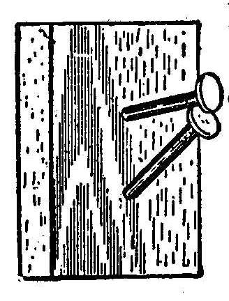
Boys will find many places around the house, where a hook to hang
things on will be a great convenience. Instead of buying hooks
use wire nails, and if driven as shown in the cut, they will
support very heavy weights. Drive the lower nail first.
A Home-Made Elderberry Huller
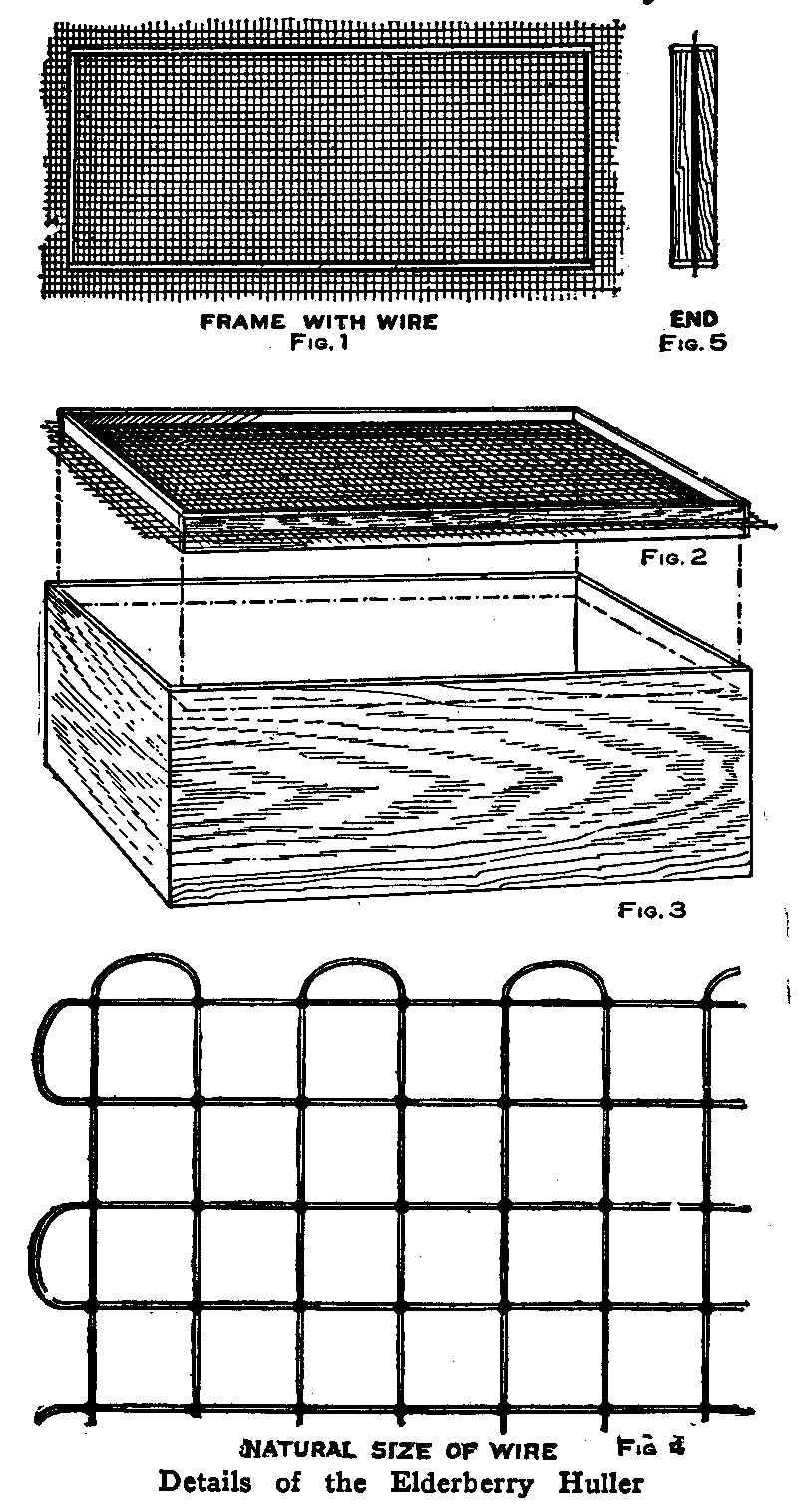
Details of the Elderberry Huller
As we had only one day to pick elderberries, we wanted to get as
many of them as we could in that time. We could pick them faster
than they could be hulled by hand so we made a huller to take
along with us to hull the berries as fast as they were picked. We
procured a box and made a frame, Fig. 1, to fit it easily, then
made another frame the same size and put a piece of wire mesh
between them as shown in Fig. 2, allowing a small portion of the
mesh to stick out of the frames. The top frame would keep the
berries from rolling or jumping off, and the bottom frame kept
the wire mesh and frame from being shaken off the box. The
projecting edges of the mesh would keep the frame on the top edge
of the box. The top view of the frame is shown in Fig. 1 and the
end in Fig. 5, and the box on which the frame rests in Fig. 3.
The actual size of the wire mesh used is shown in Fig. 4. One
person could hull with this huller as many berries as two persons
would pick.
Contributed by Albert Niemann, Pittsburg, Pa.
How to Make a Bulb on a Glass Tube
As a great many persons during the winter months are taking
advantage of the long evenings to experiment in one way or
another, the following method of forming bulbs on glass tubes may
be of interest. A common method is to heat the part to be formed
and by blowing in one end of the tube gradually expand the glass.
This way has its drawbacks, as many are not sufficiently familiar
with the work to blow a uniform blast, and the result is, a hole
is blown through the side of the tube by uneven heating or
blowing.
A good way to handle this work, is to take the tube and 1 or 2
in. more in length than the finished article is to be and place
one end over an alcohol flame, and by holding a spare piece of
tubing against the end allow them both to come to a melting heat,
then pull apart and instead of breaking off the long thread thus
formed, simply hold it in the flame at an angle of 45 deg. and
melt it down and close the end at the same time. Close the other
end with the same operation; this makes the tube airtight.
Gradually heat the tube at the point where the bulb is to be
formed, slowly turning the tube to get a uniform heat. The air
inside of the tube becoming heated will expand, and the glass,
being softer where the flame has been applied, will be pushed out
in the shape of a bulb. A great deal of care should be taken not
to go to extremes, as the bulb will burst with a loud report if
the heat is applied too long. The best results are obtained by
heating the glass slowly and then the bulb can be formed with
regularity. This is an easy way to make a thermometer tube. After
the bulb is formed, the other end of the tube can be opened by
heating, drawing out and breaking the thread like glass.
Contributed by A. Oswald.
How to Make a Sconce
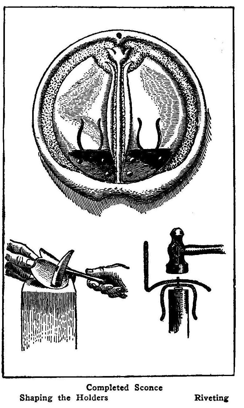
Completed Sconce
Shaping the Holders Riveting
A sconce is a candlestick holder, so made that it has a reflector
of brass or copper and is to hang upon the wall. The tools
necessary are a riveting hammer, file, metal shears, rivet punch,
flat and round-nosed pliers, screwdriver and sheet brass or
copper No. 23 gauge.
To make the sconce proceed as follows: First, cut off a piece of
brass so that it shall have 1/2 in. extra metal all around;
second, with a piece of carbon paper, trace upon the brass lines
that shall represent the margin of the sconce proper, also trace
the decorative design; third, with a nail set make a series of
holes in the extra margin about 3/4 in. apart and large enough to
take in a 3/4-in. thin screw; fourth, fasten the metal to a thick
board by inserting screws in these holes; fifth, with a
twenty-penny wire nail that has had the sharpness of its point
filed off, stamp the background of the design promiscuously. By
holding the nail about 1/4 in. above the work and striking it
with the hammer, at the same time striving to keep its point at
1/4 in. above the metal, very rapid progress can be made. This
stamping lowers the background and at the same time raises the
design. Sixth, chase or stamp along the border of the design and
background using a nail filed to a chisel edge. This is to make a
clean sharp division between background and design. Seventh, when
the stamping is complete remove the screws and metal from the
board and cut off the extra margin with the metal shears. File
the edges until they are smooth to the touch.
The drip cup is a piece of brass cut circular and shaped by
placing the brass over a hollow in one end of a block. Give the
metal a circular motion, at the same time beat it with a
round-nosed mallet. Work from the center along concentric rings
outward, then reverse.
The candle holders may have two, three, four, or six arms, and
are bent to shape by means of the round-nosed pliers. The form of
the brackets which support the drip cups may be seen in the
illustration.
Having pierced the bracket, drip cup, and holder, these three
parts are riveted together as indicated in the drawing. It will
be found easier usually if the holder is not shaped until after
the riveting is done. The bracket is then riveted to the back of
the sconce. Small copper rivets are used.
It is better to polish all the pieces before fastening any of
them together. Metal polish of any kind will do. After the parts
have been assembled a lacquer may be applied to keep the metal
from tarnishing.
How To Make a Hectograph
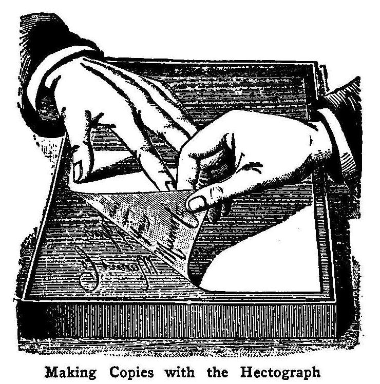
Making Copies with the Hectograph
A hectograph is very simply and easily made and by means of it
many copies of writing can be obtained from a single original.
Make a tray of either tin or pasteboard, a little larger than
the sheet of paper you ordinarily use and about 1/2 in. deep.
Soak 1 oz. of gelatine in cold water over night and in the
morning pour off the water. Heat 6-1/2 oz. of glycerine to about
200 deg. F. on a water bath, and add the gelatine. This should
give a clear glycerine solution of gelatine.
Place the tray so that it is perfectly level and pour in the
gelatinous composition until it is nearly level with the edge of
the tray. Cover it so the cover does not touch the surface of the
composition and let it stand six hours, when it will be ready for
use.
Make the copy to be reproduced on ordinary paper with aniline
ink; using a steel pen, and making the lines rather heavy so they
have a greenish color in the light. A good ink may be made of
methyl violet 2 parts, alcohol 2 parts, sugar 1 part, glycerine 4
parts, and water 24 parts. Dissolve the violet in the alcohol
mixed with the glycerine; dissolve the sugar in the water and mix
both solutions.
When the original copy of the writing is ready moisten the
surface of the hectograph slightly with a sponge, lay the copy
face down upon it and smooth down, being careful to exclude all
air bubbles and not shifting the paper. Leave it nearly a minute
and raise one corner and strip it from the pad, where will remain
a reversed copy of the inscription.
Immediately lay a piece of writing paper of the right size on the
pad, smooth it down and then remove as before. It will bear a
perfect copy of the original. Repeat the operation until the
number of copies desired is obtained or until the ink on the pad
is exhausted. Fifty or more copies can be obtained from a single
original.
When through using the hectograph wash it off with a moist
sponge, and it will be ready for future use. If the surface is
impaired at any time it can be remelted in a water bath and
poured into a tray as before, if it has not absorbed too much
ink.
How to Make a Sailomobile
By Frank Mulford, Shiloh, N. J.
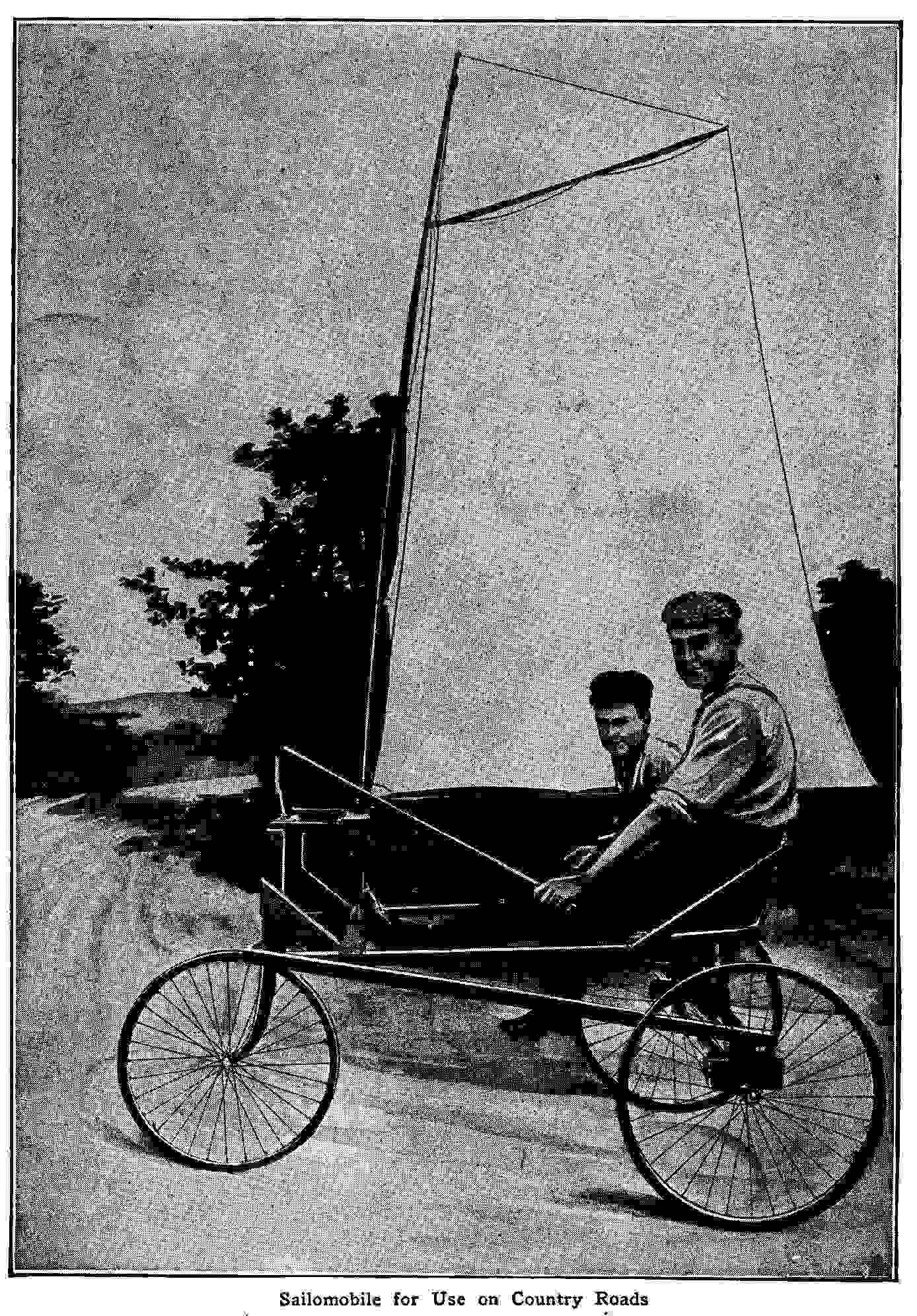
Sailomobile for Use on Country Roads
I had read of the beach automobiles used on the Florida coast;
they were like an ice boat with a sail, except they had wheels
instead of runners. So I set to work to make something to take me
over the country roads.
I found and used seven fence pickets for the frame work, and
other things as they were needed. I spliced two rake handles
together for the mast, winding the ends where they came together
with wire. A single piece would be better if you can get one long
enough. The gaff, which is the stick to which the upper end of
the sail is fastened, is a broomstick. The boom, the stick at the
bottom of the sail, was made of a rake handle with a broomstick
spliced to make it long enough. Mother let me have a sheet, which
I put down on the floor and cut into the shape of a mainsail. The
wind was the cheapest power to be found, thus it was utilized;
the three wheels were cast-off bicycle wheels.
I steer with the front wheel, which was the front wheel of an old
bicycle with the fork left on. The axle between the rear wheels
is an iron bar which cost me 15 cents, and the pulley which
raises and lowers the sail cost 5 cents. Twenty cents was all I
spent, all the rest I found.
A saw, hammer, and brace and bit were the tools used. Slats made
the seat and a cushion from the house made it comfortable, and in
a week everything was ready for sailing.
Once it was started with only my little cousin in it and I had to
run fast to catch up.
A Home-Made Magic Lantern
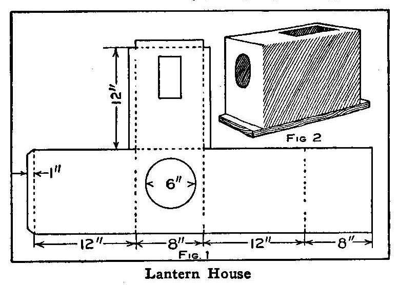
Lantern House
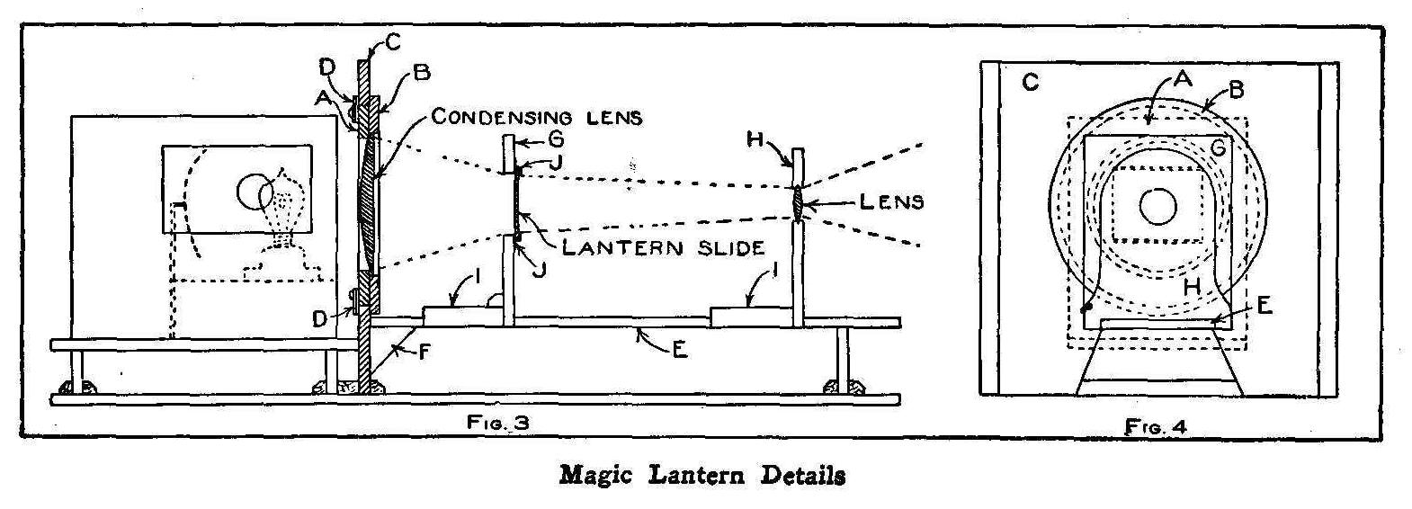
Magic Lantern Details
The essential parts of a magic lantern are a condensing lens to
make the beam of light converge upon the slide to illuminate it
evenly, a projecting lens with which to throw an enlarged picture
of the illuminated slide upon a screen and some appliances for
preserving the proper relation of these parts to each other. The
best of materials should be used and the parts put together with
care to produce a clear picture on the screen.
The first to make is the lamp house or box to hold the light. Our
illustration shows the construction for an electric light, yet
the same box may be used for gas or an oil lamp, provided the
material is of metal. A tin box having dimensions somewhere near
those given in the diagrammatic sketch may be secured from your
local grocer, but if such a box is not found, one can be made
from a piece of tin cut as shown in Fig. 1. When this metal is
bent at right angles on the dotted lines it will form a box as
shown in Fig. 2 which is placed on a baseboard, 1/2 to 3/4 in.
thick, 8 in. wide, and 14 in. long. This box should be provided
with a reflector located just back of the lamp.
Procure a plano-convex or a bi-convex 6-in. lens with a focal
length of from 15 to 20 in. and a projecting lens 2 in. in
diameter with such a focal length that will give a picture of the
required size, or a lens of 12-in. focus enlarging a 3-in. slide
to about 6 ft. at a distance of 24 ft.
The woodwork of the lantern should be of 1/2-in., well seasoned
pine, white wood or walnut and the parts fastened together with
wood screws, wire brads, or glue, as desired. The board in which
to mount the condensing lens is 16 in. wide and 15 in. high,
battened on both ends to keep the wood from warping. The board is
centered both ways, and, at a point 1 in. above the center,
describe a 9-in. circle with a compass and saw the wood out with
a scroll or keyhole saw. If a small saw is used, and the work
carefully done, the circular piece removed will serve to make the
smaller portion of the ring for holding the condensing lens. This
ring is made up from two rings, A and B, Fig. 3. The inside and
outside diameters of the ring B are 3/8 in. greater than the
corresponding diameters of ring A, so when fastened together
concentrically an inner rabbet is formed for the reception of the
lens and an outer rabbet to fit against the board C in and
against which it rotates being held in place by buttons, DD.
A table, E, about 2 ft. long is fastened to the board C with
brackets F and supported at the outer end with a standard. The
slide support, G, and the lens slide, H, are constructed to slip
easily on the table, E, the strips II serving as guides. Small
strips of tin, JJ, are bent as shown and fastened at the top and
bottom of the rectangular opening cut in the support G for
holding the lantern slides.
All the parts should be joined together snugly and the movable
parts made to slide freely and when all is complete and well
sandpapered, apply two coats of shellac varnish. Place the lamp
house on the bottom board behind the condensing lens and the
lantern is ready for use.
The proper light and focus may be obtained by slipping the
movable parts on the board E, and when the right position is
found for each, all lantern slides will produce a clear picture
on the screen, if the position of the lantern and screen is not
changed.
Contributed by Stuart Mason Kerr, St. Paul, Minn.
A Quickly Made Lamp
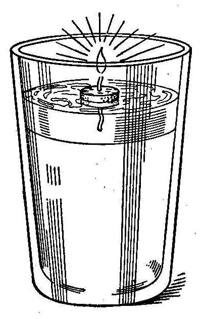
A very simple lamp can be made from materials which are available
in practically every household in the following manner: A cheap
glass tumbler is partly filled with water and then about 1/2 in.
of safe, light burning oil, placed on the water. Cut a thin strip
from an ordinary cork and make a hole in the center to carry a
short piece of wick. The wick should be of such a length as to
dip into the oil, but not long enough. To reach the water. The
upper surface of the cork may be protected from the flame with a
small piece of tin bent over the edges and a hole punched in the
center for the wick. The weight of the tin will force the cork
down into the oil. The level of the oil should be such as to make
the flame below the top of the tumbler and the light then will
not be blown out with draughts. The arrangement is quite safe as,
should the glass happen to upset, the water at once extinguishes
the flame.
Contributed by G. P. B.
How to Make a Paper Aeroplane
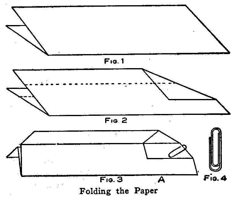
Folding the Paper
A very interesting and instructive toy aeroplane can be made as
shown in the accompanying illustrations. A sheet of paper is
first folded, Fig. 1, then the corners on one end are doubled
over, Fig. 2, and the whole piece finished up and held together
with a paper clip as in Fig. 3. The paper clip to be used should
be like the one shown in Fig. 4. If one of these clips is not at
hand, form a piece of wire in the same shape, as it will be
needed for balancing purposes as well as for holding the paper
together. Grasp the aeroplane between the thumb and forefinger at
the place marked A in Fig. 3, keeping the paper as level as
possible and throwing it as you would a dart. The aeroplane will
make an easy and graceful flight in a room where no air will
strike it.
Contributed by J.H. Crawford, Schenectady, N. Y.
Bronze Liquid
Banana oil or amyl acetate is a good bronze liquid.
A Wrestling Mat
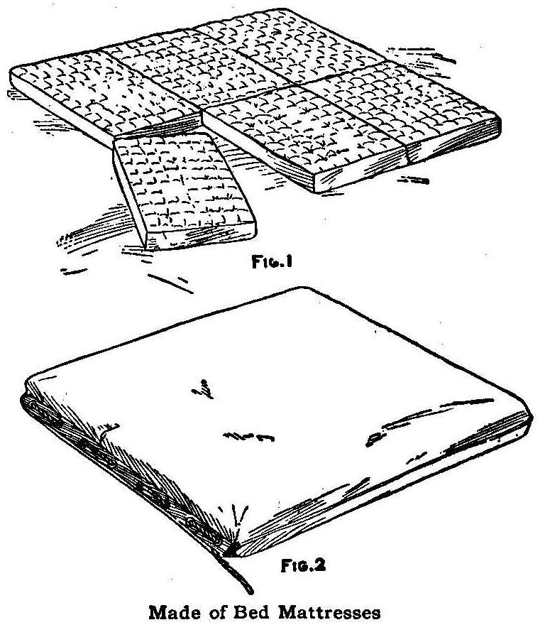
Made of Bed Mattresses
The cost of a wrestling mat is so great that few small clubs can
afford to own one. As we did not see our way clear to purchase
such a mat, I made one of six used bed mattresses (Fig. 1)
purchased from a second-hand dealer. I ordered a canvas bag, 12
ft. 3 in. by 12 ft. 9 in., from a tent company, to cover the
mattresses. The bag consisted of two pieces with the seam along
each edge. The mattresses were laid side by side and end to end
and the bag placed on and laced up as shown in Fig. 2.
Contributed by Walter W. White, Denver, Colo.
A Pocket Voltammeter
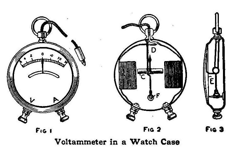
Voltammeter in a Watch Case
Remove the works and stem from a discarded dollar watch, drill
two 3/16 in. holes in the edge, 3/4 in. apart, and insert two
binding-posts, Fig. 1, insulating them from the case with
cardboard. Fold two strips of light cardboard, 1/2 in. wide, so
as to form two oblong boxes, 1/2 in. long and 3/16 in. thick,
open on the edges. On one of these forms wind evenly the wire
taken from a bell magnet to the depth of 1/8 in. and on the other
wind some 20 gauge wire to the same depth. Fasten the wire with
gummed label, to keep it from unwinding.
Glue the coils to the back of the case and connect one wire from
each binding-post as shown in Fig. 2, while the other two wires
are connected to an induction coil lead which is inserted in the
hole from which the stem was removed. Fasten a brass-headed tack
to the case at the point F with sealing wax or solder and bend a
wire in the shape shown in Fig. 3 to swing freely on the tack.
Attach a piece of steel rod, 3/4 in. long, in the center coil, C,
Fig. 2.
A rubber band, D, connects the steel rod C with the top of the
watch case. The ends of the rubber are fastened with sealing wax.
The rubber keeps the pointer at zero or in the middle of the
scale. Do not use too strong a rubber. A dial may be made by
cutting a piece of stiff white paper so it will fit under the
crystal of the watch. An arc is cut in the paper, as shown in
Fig. 1, through which the indicator works.
To calibrate the instrument, first mark the binding-post A, which
is connected to the coil of heavy wire, for amperes and the other
post, V, to the coil of small wire for volts. Connect the lead
and the post marked A to one, two and three cells and each time
mark the place of the pointer on the dial. Take corresponding
readings on a standard ammeter and mark the figures on the dial.
The volt side of the dial may be calibrated in the same manner,
using a voltmeter instead of the ammeter. The place where the
indicator comes to rest after disconnecting the current is marked
zero.
Contributed by Edward M. Teasdale, Warren, Pa.
A Film Washing Trough
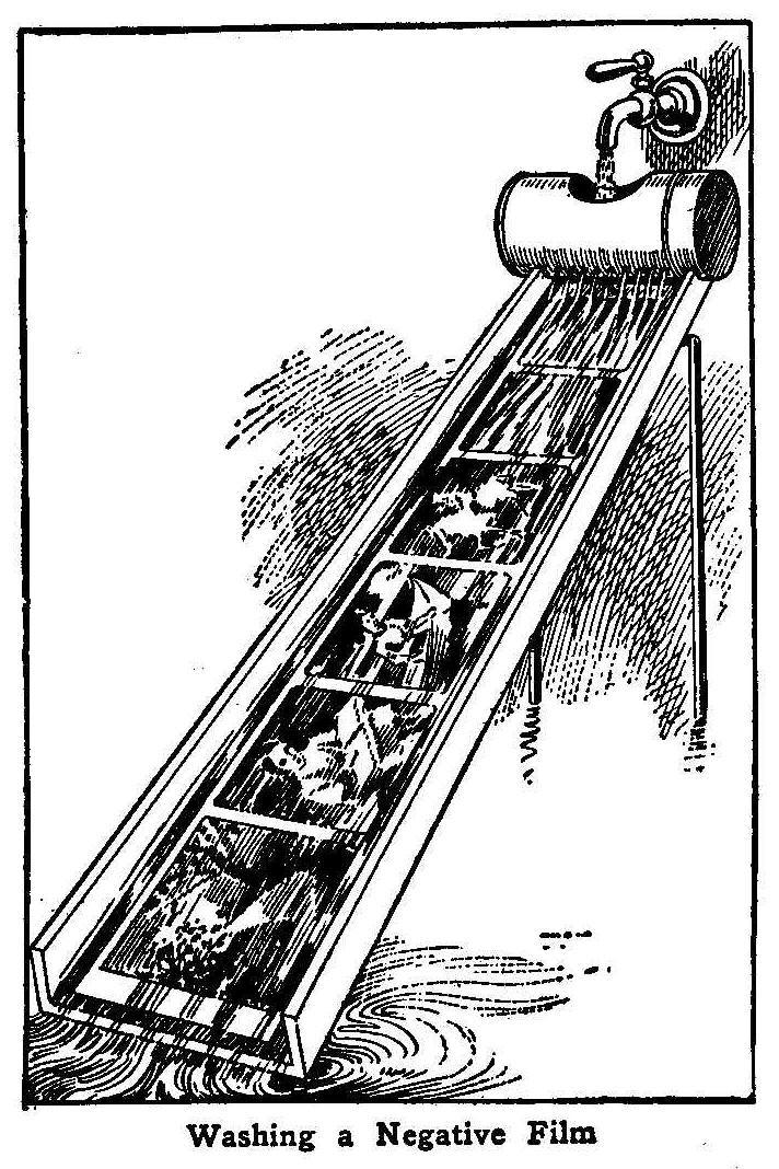
Washing a Negative Film
The washing of films without scratching them after they are
developed and fixed is very difficult in hot weather. A
convenient washing trough for washing full length films is shown
in the accompanying sketch. The trough must be made for the size
of the film to be washed. Cut a 1/4-in. board as long as the film
and a trifle wider than the film’s width. Attach strips to the
edges of the board to keep the water from spilling over the
sides.
Cut a hole in one side of a baking powder can about half way
between the top and bottom, large enough to admit a fair-sized
stream of water from a faucet. Then solder the cover to the can
and punch a number of holes about 1/4 in. apart along the
opposite side from where the large hole was cut. Place this can
on one end of the trough, as shown, with the large hole up.
Some heavy wire bent in the shape of a U and fastened to the
under side of the trough at the can end will furnish supports to
keep that end of the trough the highest and place the opening in
the can close beneath the water faucet. A common pin stuck
through one end of the film and then in the trough close to the
can will hold it in position for washing. Five minutes’ washing
with this device is sufficient to remove all traces of the hypo
from the film.
Contributed by M. M. Hunting, Dayton, O.
Wood Burning
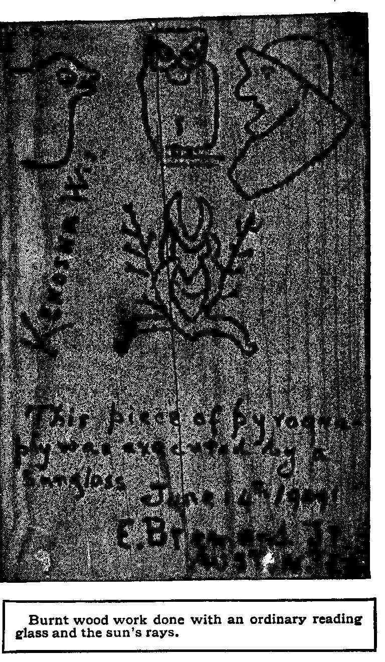
Burnt wood work done with an ordinary reading glass and the sun’s
rays.
The Diving Bottle
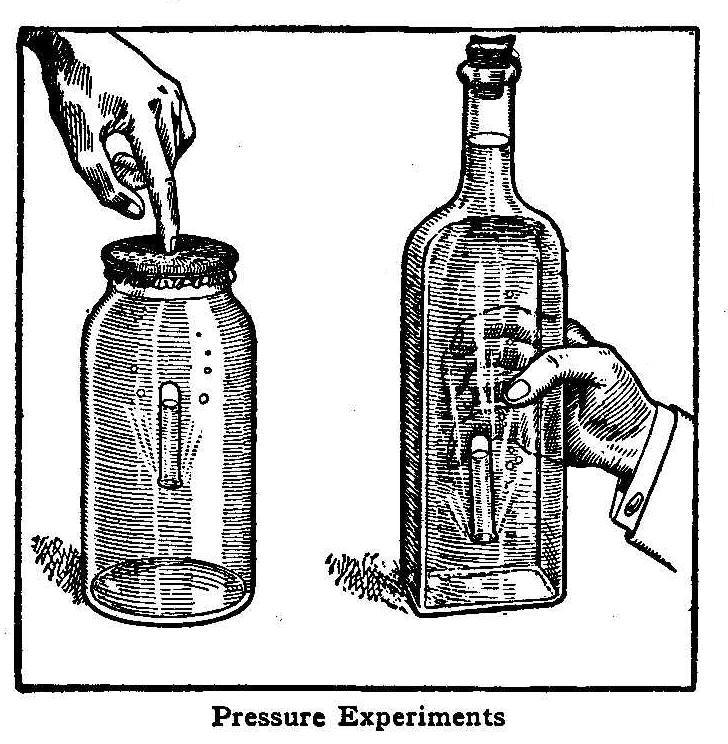
Pressure Experiments
This is a very interesting and easily performed experiment
illustrating the transmission of pressure by liquids. Take a
wide-mouthed bottle and fill almost full of water; then into this
bottle place, mouth downward, a small vial or bottle having just
enough air in the bottle to keep it barely afloat. Put a sheet of
rubber over the mouth of the large bottle, draw the edge down
over the neck and wrap securely with a piece of string thus
forming a tightly stretched diaphragm over the top. When a finger
is pressed on the rubber the small bottle will slowly descend
until the pressure is released when the small bottle wilt ascend.
The moving of the small bottle is caused by the pressure
transmitted through the water, thus causing the volume of air in
the small tube to decrease and the bottle to descend and ascend
when released as the air increases to the original volume.
This experiment can be performed with a narrow-necked bottle,
provided the bottle is wide, but not very thick. Place the small
bottle in as before, taking care not to have too much air in the
bottom. If the cork is adjusted properly, the bottle may be held
in the hand and the sides pressed with the fingers, thus causing
the small bottle to descend and ascend at will. If the small
bottle used is opaque, or an opaque tube such as the cap of a
fountain pen, many puzzling effects may be obtained.
Contributed by John Shahan, Auburn, Ala.
How to Make an Inexpensive Wooden Fan
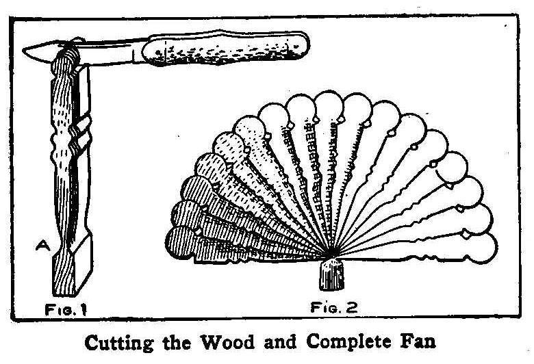
Cutting the Wood and Complete Fan
Select a nice straight-grained piece of white pine about 1/4 in.
thick, 3/4 in. wide and 4 in. long. Lay out the design desired
and cut as shown in Fig. 1, and then soak the wood in hot water
to make it soft and easy to split. Cut the divisions very thin
with a sharp knife down to the point A, as shown in the sketch,
taking care not to split the wood through the part left for the
handle. The fan is then finished by placing each piece over the
other as in Fig. 2. This will make a very pretty ornament.
Contributed by Fred W. Whitehouse, Upper Troy, N.Y.
Combination Telegraph and Telephone Line
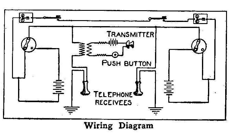
Wiring Diagram
The accompanying diagrams show connections for a short line
system (metallic circuit) of telegraph where a telephone may be
used in combination on the line. The telephone receivers can be
used both as receivers and transmitters, or ordinary telephone
transmitters, induction coils and battery may be used in the
circuit with a receiver. If a transmitter is used, its batteries
may be connected in circuit with a common push button which is
held down when using the telephone. On a 1000-ft. line, four dry
cells will be sufficient for the telegraph instruments and two
cells for the telephone.
Contributed by D. W. Miller.
How to Make a Miniature Windmill
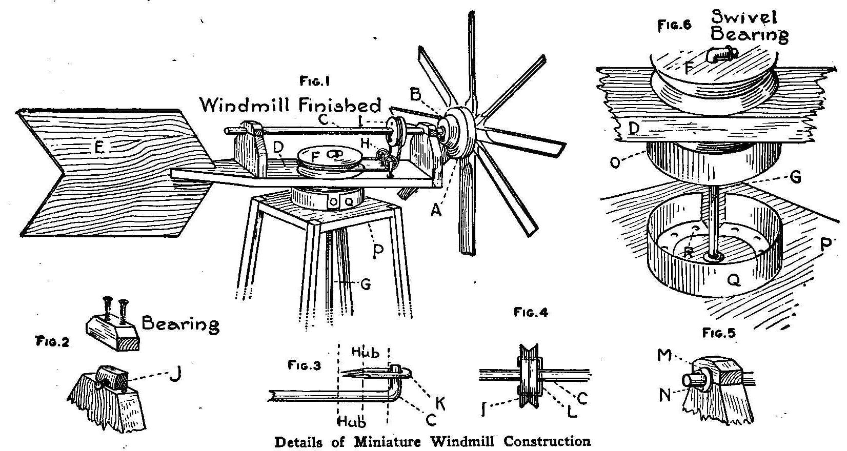
Details of Miniature Windmill Construction
The following description is how a miniature windmill was made,
which gave considerable power for its size, even in a light
breeze. Its smaller parts, such as blades and pulleys, were
constructed of 1-in. sugar pine on account of its softness.
The eight blades were made from pieces 1 by 1-1/2 by 12 in. Two
opposite edges were cut away until the blade was about 1/8 in.
thick. Two inches were left uncut at the hub end. They were then
nailed to the circular face plate A, Fig. 1, which was 6 in. in
diameter and 1 in. thick. The center of the hub was lengthened by
the wooden disk, B, Fig. 1, which was nailed to the face plate.
The shaft C, Fig. 1, was 1/4-in. iron rod, 2 ft. long, and turned
in the bearings detailed in Fig. 2. J was a nut from a wagon bolt
and was placed in the bearing to insure easy running. The bearing
blocks were 3 in. wide, 1 in. thick and 3 in. high without the
upper half. Both bearings were made in this manner.
The shaft C was keyed to the hub of the wheel, by the method
shown in Fig. 3. A staple, K, held the shaft from revolving in
the hub. This method was also applied in keying the 5-in. pulley
F, to the shaft, G, Fig. 1, which extended to the ground. The
2-1/2 in. pulley, I, Fig. 1, was keyed to shaft C, as shown in Fig.
4. The wire L was put through the hole in the axle and the two
ends curved so as to pass through the two holes in the pulley,
after which they were given a final bend to keep the pulley in
place. The method by which the shaft C was kept from working
forward is shown in Fig. 5. The washer M intervened between the
bearing block and the wire N, which was passed through the axle
and then bent to prevent its falling out. Two washers were placed
on shaft C, between the forward bearing and the hub of the wheel
to lessen the friction.
The bed plate D, Fig. 1, was 2 ft. long, 3 in. wide and 1 in.
thick and was tapered from the rear bearing to the slot in which
the fan E was nailed. This fan was made of 1/4-in. pine 18 by 12
in. and was cut the shape shown.
The two small iron pulleys with screw bases, H, Fig. 1, were
obtained for a small sum from a hardware dealer. Their diameter
was 1-1/4 in. The belt which transferred the power from shaft C
to shaft G was top string, with a section of rubber in it to take
up slack. To prevent it from slipping on the two wooden pulleys a
rubber band was placed in the grooves of each.
The point for the swivel bearing was determined by balancing the
bed plate, with all parts in place, across the thin edge of a
board. There a 1/4-in. hole was bored in which shaft G turned. To
lessen the friction here, washers were placed under pulley F. The
swivel bearing was made from two lids of baking powder cans. A
section was cut out of one to permit its being enlarged enough to
admit the other. The smaller one, 0, Fig. 6, was nailed top down
with the sharp edge to the underside of the bed plate, so that
the 1/4-in. hole for the shaft G was in the center. The other
lid, G, was tacked, top down also, in the center of the board P,
with brass headed furniture tacks, R, Fig. 6, which acted as a
smooth surface for the other tin to revolve upon. Holes for shaft
G were cut through both lids. Shaft G was but 1/4 in. in
diameter, but to keep it from rubbing against the board P, a
1/2-in. hole was bored for it, through the latter.
The tower was made of four 1 by 1 in. strips, 25 ft. long. They
converged from points on the ground forming an 8-ft. square to
the board P at the top of the tower. This board was 12 in. square
and the corners were notched to admit the strips as shown, Fig.
1. Laths were nailed diagonally between the strips to strengthen
the tower laterally. Each strip was screwed to a stake in the
ground so that by disconnecting two of them the other two could
be used as hinges and the tower could be tipped over and lowered
to the ground, as, for instance, when the windmill needed oiling.
Bearings for the shaft G were placed 5 ft. apart in the tower.
The power was put to various uses.
How to Make a Telegraph Instrument and Buzzer
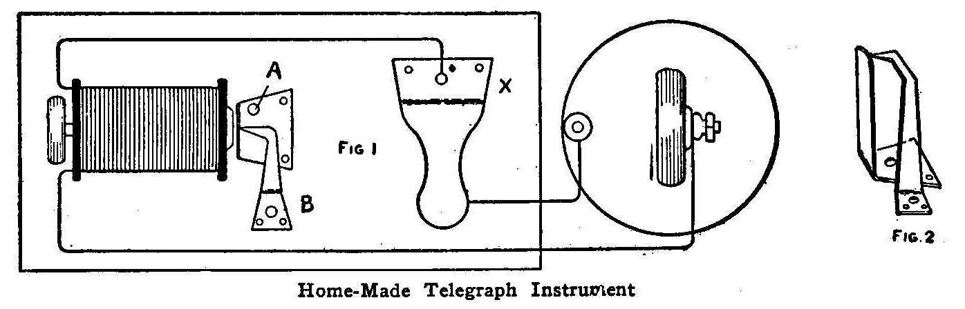
Home-Made Telegraph Instrument
The only expenditure necessary in constructing this telegraph
instrument is the price of a dry cell, providing one has a few
old materials on hand.
Procure a block of wood about 6 in. long and 3 in. wide and take
the coils out of an old electric bell. If you have no bell, one
may be had at the dealers for a small sum. Fasten these coils on
the blocks at one end as in Fig. 1.
Cut a piece of tin 2 in. long and 1/2 in. wide and bend it so the
end of the tin when fastened to the block will come just above
the core of the coil. Cut another piece of tin 3 in. long and
bend it as shown at A, Fig. 2. Tack these two pieces of tin in
front of the coils as shown in the illustration. This completes
the receiver or sounder.
To make the key, cut out another piece of tin (X, Fig. 1) 4 in.
long and bend it as shown. Before tacking it to the board, cut
off the head of a nail and drive it in the board at a point where
the loose end of the tin will cover it. Then tack the key to the
board and connect the wires of the battery as in Fig. 1. Now,
move the coils back and forth until the click sounds just the way
you wish and you are ready to begin on the Morse code.
When tired of this instrument, connect the wire from the coils to
the key to point A and the one connected at the point under the
key to B, leaving the other wire as it is. By adjusting the
coils, the receiver will begin to vibrate rapidly, causing a
buzzing sound.
Contributed by John R. McConnell.
How to Make a Water Bicycle
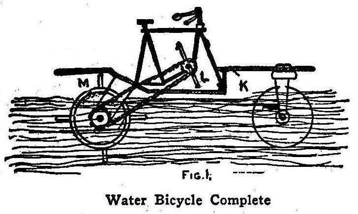
Water, Bicycle Complete
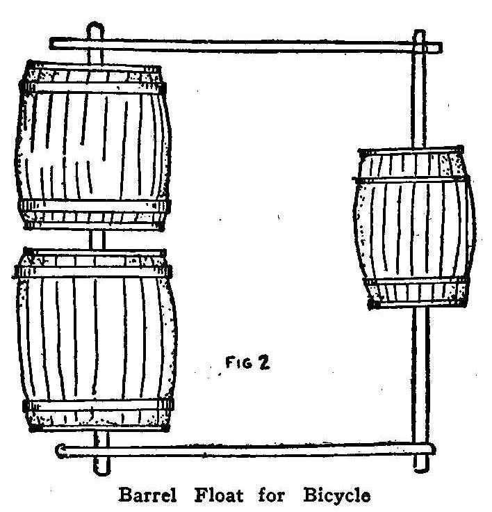
Barrel Float for Bicycle
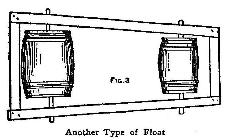
Another Type of Float
Water bicycles afford fine sport, and, like many another device
boys make, can be made of material often cast off by their people
as rubbish. The principle material necessary for the construction
of a water bicycle is oil barrels. Flour barrels will not do-they
are not strong enough, nor can they be made perfectly airtight.
The grocer can furnish you with oil barrels at a very small cost,
probably let you have them for making a few deliveries for him.
Three barrels are required for the water bicycle, although it can
be made with but two. Figure 1 shows the method of arranging the
barrels; after the manner of bicycle wheels.
Procure an old bicycle frame and make for it a board platform
about 3 ft. wide at the rear end and tapering to about 2 ft. at
the front, using cleats to hold the board frame, as shown at the
shaded portion K. The construction of the barrel part is shown in
Fig. 2. Bore holes in the center of the heads of the two rear
barrels and also in the heads of the first barrel and put a shaft
of wood, through the rear barrels and one through the front
barrel, adjusting the side pieces to the shafts, as indicated.
Next place the platform of the bicycle frame and connections
thereon. Going back to Fig. 1 we see that the driving chain
passes from the sprocket driver L of the bicycle frame to the
place downward between the slits in the platform to the driven
sprocket on the shaft between the two barrels. Thus a center
drive is made. The rear barrels are, fitted with paddles as at M,
consisting of four pieces of board nailed and cleated about the
circumference of the barrels, as shown in Fig. 1.
The new craft
is now ready for a first voyage. To propel it, seat yourself on
the bicycle seat, feet on the pedals, just as you would were you
on a bicycle out in the street. The steering is effected by
simply bending the body to the right or left, which causes the
craft to dip to the inclined side and the affair turns in the
dipped direction. The speed is slow at first, but increases as
the force is generated and as one becomes familiar with the
working of the affair. There is no danger, as the airtight
barrels cannot possibly sink.
Another mode of putting together the set of barrels, using one
large one in the rear and a small one in the front is presented
in Fig, 3. These two barrels are empty oil barrels like the
others. The head holes are bored and the proper wooden shafts are
inserted and the entrance to the bores closed tight by calking
with hemp and putty or clay. The ends of the shafts turn in the
wooden frame where the required bores are made to receive the
same. If the journals thus made are well oiled, there will not be
much friction. Such a frame can be fitted with a platform and a
raft to suit one’s individual fancy built upon it, which can be
paddled about with ease and safety on any pond. A sail can be
rigged up by using a mast and some sheeting; or even a little
houseboat, which will give any amount of pleasure, can be built.
How To Make a Small Searchlight
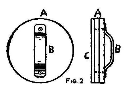
Front View Side View
The materials required for a small searchlight are a 4-volt lamp
of the loop variety, thin sheet brass for the cylinder, copper
piping and brass tubing for base. When completed the searchlight
may be fitted to a small boat and will afford a great amount of
pleasure for a little work, or it may be put to other uses if
desired. Make a cylinder of wood of the required size and bend a
sheet of thin brass around it. Shape small blocks of boxwood, D,
Fig. 1, to fit the sides and pass stout pieces of brass wire
through the middle of the blocks for trunnions. Exactly through
the middle of the sides of the cylinder drill holes just so large
that when the blocks containing the trunnions are cemented to the
cylinder there is no chance of contact between cylinder and
trunnion, and so creating a false circuit.
The trunnion should project slightly into the cylinder, and after
the lamp has been placed in position by means of the small wood
blocks shown in Fig. 1, the wires from the lamp should be
soldered to the trunnions. It is best to solder the wire to the
trunnions before cementing the side blocks inside the cylinder.
Turn a small circle of wood, A, Fig. 2, inside the cylinder to
fit exactly and fasten to it a piece of mirror, C, Fig. 2,
exactly the same size to serve as a reflector. Painting the wood
with white enamel or a piece of brightly polished metal will
serve the purpose. On the back of the piece of wood fasten a
small brass handle, B, Fig. 2, so that it may readily be removed
for cleaning.
In front of cylinder place a piece of magnifying glass for a
lens. If a piece to fit cannot be obtained, fit a glass like a
linen tester to a small disc of wood or brass to fit the
cylinder. If magnifying glass cannot be had, use plain glass and
fit them as follows:
Make two rings of brass wire to fit tightly into the cylinder,
trace a circle (inside diameter of cylinder) on a piece of
cardboard; place cardboard on glass and cut out glass with a
glass cutter; break off odd corners with notches on cutters and
grind the edge of the glass on an ordinary red brick using plenty
of water. Place one brass ring in cylinder, then the glass disc
and then the other ring.
For the stand fill a piece of copper piping with melted rosin or
lead.
When hard bend the pipe around a piece of wood which has
been sawed to the shape of bend desired. Then melt out the rosin
or lead.
Make an incision with a half-round file in the under
side of the tube for the wires to come through. Make the base of
wood as shown in Fig. 1. One half inch from the top bore a hole
large enough to admit the copper pipe and a larger hole up the
center to meet it for the wires to come down.
If it is desired to make the light very complete, make the base
of two pieces of brass tube—one being a sliding fit in the other
and with projecting pieces to prevent the cylinder from going too
far. The light may then be elevated or lowered as wished. On two
ordinary brass terminals twist or solder some flexible wire, but
before doing so fix a little bone washer on the screws of the
terminal so as to insulate it from the tube. When the wires have
been secured to the terminals cover the joint with a piece of
very thin india rubber tubing, such as is used for cycle valves.
The two wires may now be threaded down the copper tube into the
base, and pulled tight, the terminals firmly fixed into the
tubes; if too small, some glue will secure them. To get the
cylinder into its carriage, put one trunnion into the terminal as
far as it will go and this will allow room for the other trunnion
to go in its terminal.
Electric Alarm that Rings a Bell and Turns on a Light
Details of Alarm Construction
The illustration shows an alarm clock connected up to ring an
electric bell, and at the same time turn on an electric light to
show the time. The parts indicated are as follows: A, key of
alarm clock; B, contact post, 4 in. long; C, shelf, 5-1/4 by 10
in.; D, bracket; E, electric bulb (3-1/2 volts); S, brass strip,
4-1/2 in. long, 3/8 in. wide and 1/16 in. thick; T, switch; F,
wire from batteries to switch; G, wire from bell to switch; H,
wire from light to switch; I, dry batteries; J, bell; X, point
where a splice is made from the light to wire leading to
batteries from brass strip under clock. Push the switch lever to
the right before retiring.
To operate this, set alarm key as shown in diagram, after two
turns have been made on the key. When alarm goes off, it turns
till it forms a connection by striking the contact post and
starts the electric bell ringing. Throw lever off from the right
to center, which stops bell ringing. To throw on light throw
levers to the left. The bell is then cut out but the light
remains on till lever is again thrown in the center,
In placing clock on shelf, after setting alarm, be sure that the
legs of clock are on the brass strip and that the alarm key is in
position so it will come in contact with the contact post in back
of clock. The contact post may be of 1/4-in. copper tubing, or
1/4-in. brass rod.
The advantage of this is that one can control the bell and light,
while lying in bed, by having the switch on the baseboard, near
the bed, so it can be reached without getting out of bed.
Contributed by Geo. C. Brinkerhoff, Swissvale, Pa.
How to Hold a Screw on a Screwdriver
A screw that is taken from a place almost inaccessible with the
fingers requires considerable patience to return it with an
ordinary screwdriver unless some holding-on device is used. I
have found that by putting a piece of cardboard or thick paper
with the blade of the screwdriver in the screw head slot, the
screw may be held and turned into places that it would be
impossible with the screwdriver alone.
Contributed by C. Chatland, Ogden, Utah.
How to Make a Lead Cannon
Lead Cannon Construction
Any boy who has a little mechanical ability can make a very
reliable cannon for his Fourth-of-July celebration by following
the instructions given here:
Take a stick—a piece of curtain roller will do—7 in. long. Make
a shoulder, as at A, Fig. 1, 4 in. from one end, making it as
true and smooth as possible, as this is to be the muzzle of the
cannon. Make the spindle as in Fig. 1, 1/4 in. in diameter.
Procure a good quality of stiff paper, about 6 in. wide, and wrap
it around the shoulder of the stick, letting it extend 3/4 in.
beyond the end of the spindle, as at B, Fig. 2. Push an ordinary
shingle nail through the paper and into the extreme end of the
spindle, as at A, Fig. 2. This is to form the fuse hole.
Having finished this, place stick and all in a pail of sand,
being careful not to get the sand in it, and letting the opening
at the top extend a little above the surface of the sand. Then
fill the paper cylinder with melted
lead and let cool. Pull out
the nail and stick, scrape off the paper and the cannon is ready
for mounting, as in Fig. 3.
Contributed by Chas. S. Chapman, Lanesboro, Minn.
Homemade Electric Bed Warmer
The heat developed by a carbon-filament lamp is sufficiently high
to allow its use as a heating element of, for instance, a bed
warmer. There are a number of other small heaters which can be
easily made and for which lamps form very suitable heating elements,
but the bed warmer is probably the best example. All that
is required is a tin covering, which can be made of an old can,
about 3-1/2 in. in diameter. The top is cut out and the edge
filed smooth. The lamp-socket end of the flexible cord is
inserted in the can and the shade holder gripped over the
opening. A small lamp of about 5 cp. will do the heating.
A flannel bag, large enough to slip over the tin can and provided
with a neck that can be drawn together by means of a cord, gives
the heater a more finished appearance, as well as making it more
pleasant to the touch.
Making a Fire with the Aid of Ice
Forming the Ice Lens
Take a piece of very clear ice and melt it down into the hollow
of your hands so as to form a large lens. The illustration shows
how this is done. With the lens-shaped ice used in the same
manner as a reading glass to direct the sun’s rays on paper or
shavings you can start a fire.
Contributed by Arthur E. Joerin.
How to Make a Crossbow and Arrow Sling
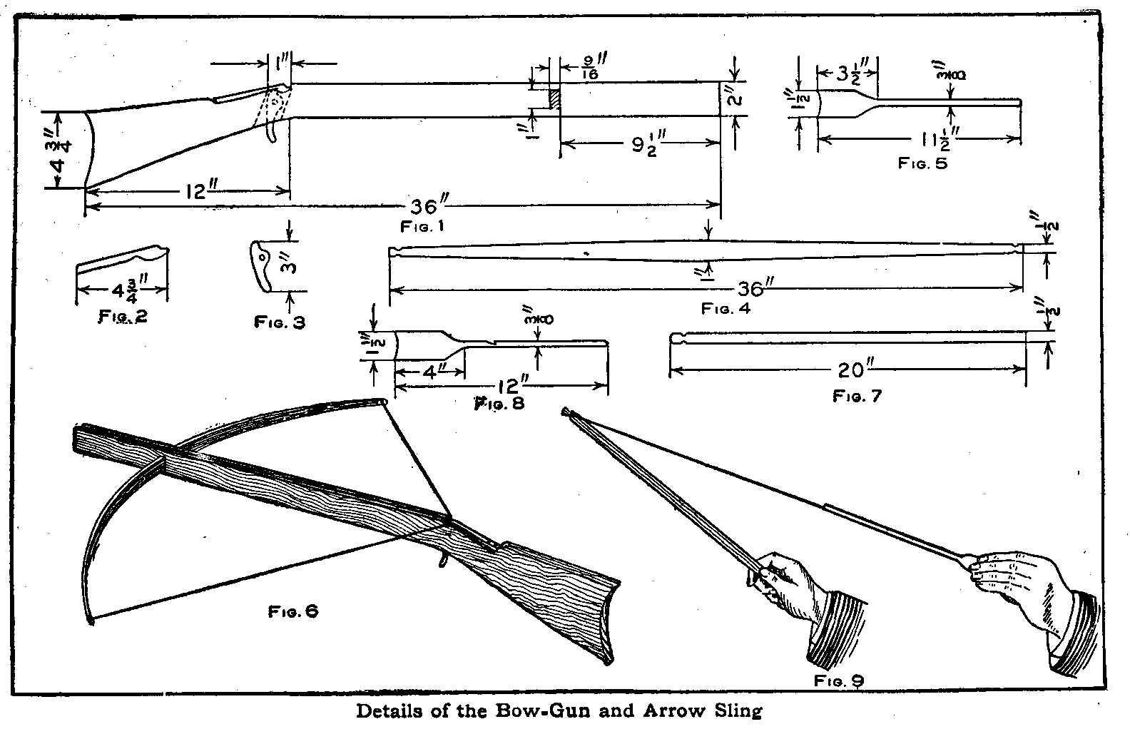
Details of the Bow-Gun and Arrow Sling
In making of this crossbow it is best to use maple for the stock,
but if this wood cannot be procured, good straight-grained pine
will do. The material must be 1-1/2 in. thick, 6 in. wide and a
trifle over 3 ft. long. The bow is made from straight-grained
oak, ash, or hickory, 5/8 in. thick, 1 in. wide and 3 ft. long. A
piece of oak, 3/8 in. thick, 1-1/2 in. wide and 6 ft. long, will
be sufficient to make the trigger, spring and arrows. A piece of
tin, some nails and a good cord will complete the materials
necessary to make the crossbow.
The piece of maple or pine selected for the stock must be planed
and sandpapered on both sides, and then marked and cut as shown
in Fig. 1. A groove is cut for the arrows in the top straight
edge 3/8 in. wide and 3/8 in. deep. The tin is bent and fastened
on the wood at the back end of the groove where the cord slips
out of the notch; this is to keep the edges from splitting.
A mortise is cut for the bow at a point 9-1/2 in. from the end of
the stock, and one for the trigger 12 in. from the opposite end,
which should be slanting a little as shown by the dotted lines. A
spring, Fig. 2, is made from a good piece of oak and fastened to
the stock with two screws. The trigger, Fig. 3, which is 1/4 in.
thick, is inserted in the mortise in the position when pulled
back, and adjusted so as to raise the spring to the proper
height, and then a pin is put through both stock and trigger,
having the latter swing quite freely. When the trigger is pulled,
it lifts the spring up, which in turn lifts the cord off the tin
notch.
The stick for the bow, Fig. 4, is dressed down from a point 3/4
in. on each side of the center line to 1/2 in. wide at each end.
Notches are cut in the ends for the cord. The bow is not fastened
in the stock, it is wrapped with a piece of canvas 1-1/2 in. wide
on the center line to make a tight fit in the mortise. A stout
cord is now tied in the notches cut in the ends of the bow making
the cord taut when the wood is straight.
The design of the arrows is shown in Fig. 5 and they are made
with the blades much thinner than the round part.
To shoot the crossbow, pull the cord back and down in the notch
as shown in Fig. 6, place the arrow in the groove, sight and pull
the trigger as in shooting an ordinary gun.
The arrow sling is made from a branch of ash about 1/2 in. in
diameter, the bark removed and a notch cut in one end, as shown
in Fig. 7. A stout cord about 2-1/2 ft. long is tied in the notch
and a large knot made in the other or loose end. The arrows are
practically the same as those used on the crossbow, with the
exception of a small notch which is cut in them as shown in Fig.
8.
To throw the arrow, insert the cord near the knot in the notch of
the arrow, then grasping the stick with the right hand and
holding the wing of the arrow with the left, as shown in Fig. 9,
throw the arrow with a quick slinging motion. The arrow may be
thrown several hundred feet after a little practice.
Contributed by O. E. Trownes, Wilmette, Ill.
A Home-Made Vise
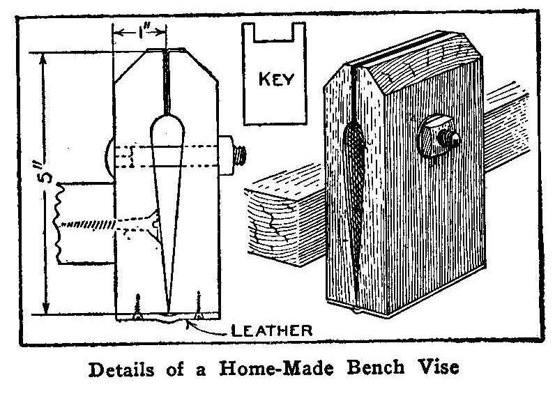
Details of a Home-Made Bench Vise
Cut two pieces of wood in the shape shown in the sketch and bore
a 3/8-in. hole through both of them for a common carriage bolt.
Fasten one of the pieces to the edge of the bench with a large
wood screw and attach the other piece to the first one with a
piece of leather nailed across the bottom of both pieces. The nut
on the carriage bolt may be tightened with a wrench, or, better
still, a key filed out of a piece of soft steel to fit the nut.
The edges of the jaws are faced with sheet metal which can be
copper or steel suitable for the work it is intended to hold.
Temporary Dark Room Lantern
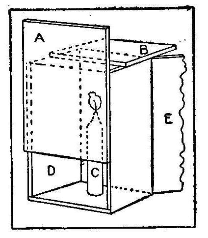
Occasionally through some accident to the regular ruby lamp, or
through the necessity of developing while out of reach of a
properly equipped dark room, some makeshift of illumination must
be improvised. Such a temporary safe light may be made from an
empty cigar box in a short time.
Remove the bottom of the box, and nail it in position as shown
at A. Remove one end, and replace as shown at B. Drive a short
wire nail through the center of the opposite end to serve as a
seat for the candle, C. The lamp is finished by tacking two or
more layers of yellow post-office paper over the aperture D,
bringing the paper well around to the sides and bottom of the box
to prevent light leakage from the cracks around the edges, says
Photo Era. The hinged cover E, is used as a door, making lighting
and trimming convenient. The door may be fastened with a nail or
piece of wire. It is well to reinforce the hinge by gluing on a
strip of cloth if the lamp is to be in use more than once or
twice. This lamp is safe, for the projecting edges of A and B
form light-shields for the ventilation orifice and the crack at
the top of the hinged cover, respectively. Moreover, since the
flame of the candle is above A, only reflected and transmitted
light reaches the plate, while the danger of igniting the paper
is reduced to a minimum.
Runny Paint
The paint will sag and run if too much oil is put in
white lead.
Camps and How to Build Them
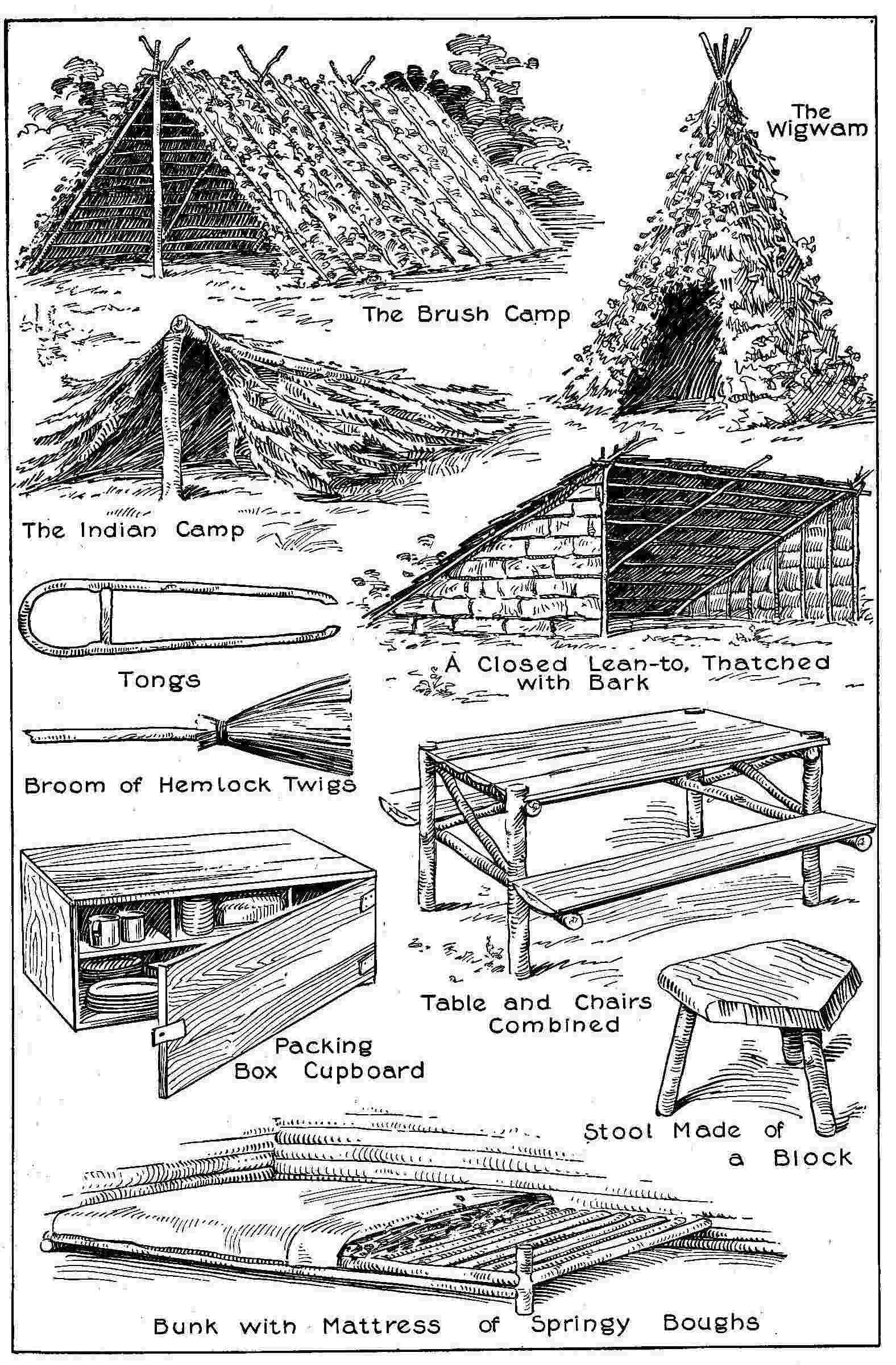
There are several ways of building a temporary camp from material
that is always to be found in the woods, and whether these
improvised shelters are intended to last until a permanent camp
is built, or only as a camp on a short excursion, a great deal of
fun can be had in their construction. The Indian camp is the
easiest to make. An evergreen tree with branches growing well
down toward the ground furnishes all the material. By chopping
the trunk almost through, so that when the tree falls the upper
part will still remain attached to the stump, a serviceable
shelter can be quickly provided. The cut should be about 5 ft.
from the ground. Then the boughs and branches on the under side
of the fallen top are chopped away and piled on top. There is
room for several persons under this sort of shelter, which offers
fairly good protection against any but the most drenching rains.
The Indian wigwam sheds rain better, and where there are no
suitable trees that can be cut, it is the easiest camp to make.
Three long poles with the tops tied together and the lower ends
spaced 8 or 10 ft. apart, make the frame of the wigwam. Branches
and brush can easily be piled up, and woven in and out on these
poles so as to shed a very heavy rain.
The brush camp is shaped like an ordinary “A” tent. The ridge
pole should be about 8 ft. long and supported by crotched
uprights about 6 ft. from the ground. Often the ridge pole can be
laid from one small tree to another. Avoid tall trees on account
of lightning. Eight or ten long poles are then laid slanting
against the ridge pole on each side. Cedar or hemlock boughs make
the best thatch for the brush camp. They should be piled up to a
thickness of a foot or more over the slanting poles and woven in
and out to keep them from slipping. Then a number of poles should
be laid over them to prevent them from blowing away.
In woods where there is plenty of bark available in large slabs,
the bark lean-to is a quickly constructed and serviceable camp.
The ridge pole is set up like that of the brush camp. Three or
four other poles are laid slanting to the ground on one side
only. The ends of these poles should be pushed into the earth and
fastened with crotched sticks. Long poles are then laid crossways
of these slanting poles, and the whole can be covered with brush
as in the case of the brush camp or with strips of bark laid
overlapping each other like shingles. Where bark is used, nails
are necessary to hold it in place. Bark may also be used for a
wigwam and it can be held in place by a cord wrapped tightly
around the whole structure, running spiral-wise from the ground
to the peak. In the early summer, the bark can easily be removed
from most trees by making two circular cuts around the trunk and
joining them with another vertical cut. The bark is easily pried
off with an ax, and if laid on the ground under heavy stones,
will dry flat. Sheets of bark, 6 ft. long and 2 or 3 ft. wide,
are a convenient size for camp construction.
The small boughs and twigs of hemlock, spruce, and cedar, piled 2
or 3 ft. deep and covered with blankets, make the best kind of a
camp bed. For a permanent camp, a bunk can be made by laying
small poles close together across two larger poles on a rude
framework easily constructed. Evergreen twigs or dried leaves are
piled on this, and a blanket or a piece of canvas stretched
across and fastened down to the poles at the sides. A bed like
this is soft and springy and will last through an ordinary
camping season without renewal. A portable cot that does not take
up much room in the camp outfit is made of a piece of heavy
canvas 40 in. wide and 6 ft. long. Four-inch hems are sewed in
each side of the canvas, and when the camp is pitched, a 2-in.
pole is run through each hem and the ends of the pole supported
on crotched sticks.
Fresh water close at hand and shade for the middle of the day are
two points that should always be looked for in. selecting a site
for a camp. If the camp is to be occupied for any length of time,
useful implements for many purposes can be made out of such
material as the woods afford. The simplest way to build a crane
for hanging kettles over the campfire is to drive two posts into
the ground, each of them a foot or more from one end of the fire
space, and split the tops with an ax, so that a pole laid from
one to the other across the fire will be securely held in the
split. Tongs are very useful in camp. A piece of elm or hickory,
3 ft. long and 1-1/2 in. thick, makes a good pair of tongs. For a
foot in the middle of the stick, cut half of the thickness away
and hold this part over the fire until it can be bent easily to
bring the two ends together, then fasten a crosspiece to hold the
ends close together, shape the ends so that anything that drops
into the fire can be seized by them, and a serviceable pair of
tongs is the result. Any sort of a stick that is easily handled
will serve as a poker. Hemlock twigs tied around one end of a
stick make an excellent broom. Movable seats for a permanent camp
are easily made by splitting a log, boring holes in the rounded
side of the slab and driving pegs into them to serve as legs. A
short slab or plank can easily be made into a three-legged stool
in the same way.
Campers usually have boxes in which their provisions have been
carried. Such a packing box is easily made into a cupboard, and
it is not difficult to improvise shelves, hinges, or even a rough
lock for the camp larder.
A good way to make a camp table is to set four posts into the
ground and nail crosspieces to support slabs cut from chopped
wood logs to form a top. Pieces can be nailed onto the legs of
the table to hold other slabs to serve as seats, and affording
accommodation for several persons.
Brooder for Small Chicks
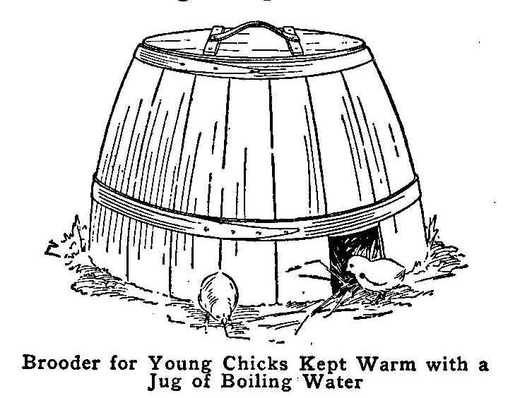
Brooder for Young Chicks Kept Warm with a Jug of Boiling Water
A very simple brooder can be constructed by cutting a sugar
barrel in half and using one part in the manner described. Line
the inside of the half barrel with paper and then cover this
with old flannel cloth. Make a cover for the top and line it in
the same manner. At the bottom cut a hole in the edge, about 4
in. deep and 4 in. wide, and provide a cover or door. The inside
is kept warm by filling a jug with boiling water and setting it
within, changing the water both morning and night. When the
temperature outside is 10 deg. the interior can, be kept at 90 or
100 deg., but the jug must be refilled with boiling water at
least twice a day.
Faucet Used as an Emergency Plug
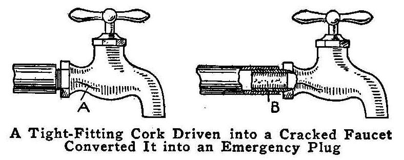
A Tight-Fitting Cork Driven into a Cracked Faucet Converted It into an
Emergency Plug
A brass faucet split as shown at A during a cold spell, and as no
suitable plug to screw into the elbow after removing the faucet
was at hand, I drove a small cork, B, into the end of the faucet
and screwed it back in place. The cork converted the faucet into
an emergency plug which prevented leakage until the proper
fitting to take its place could be secured.
Contributed by James M. Kane, Doylestown, Pa.
Automatic Electric Heat Regulator
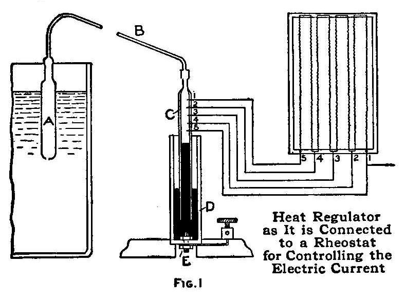
Heat Regulator as it is Connected
to a Rheostat for Controlling
the Electric Current.
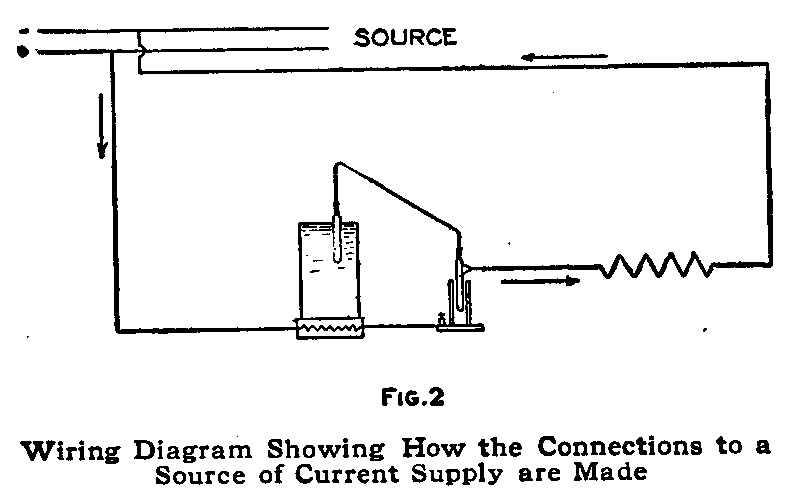
Wiring Diagram Showing How the Connections to a Source of Current
Supply are Made
It is composed of a closed glass tube, A, Fig. 1, connected by
means of a very small lead
pipe, B, to another glass tube, C,
open at the bottom and having five pieces of platinum wire (1, 2,
3, 4 and 5), which project inside and outside of the tube, fused
into one side. This tube is plunged into an ebonite vessel of
somewhat larger diameter, which is fastened to the base by a
copper screw, E. The tube C is filled to a certain height with
mercury and then petroleum.
The outer ends of the five platinum
wires are soldered to ordinary copper wires and connections made
to various points on a rheostat as shown. The diagram, Fig. 2,
shows how the connections to the supply current are made.
The apparatus operates as follows: The tube is immersed in the
matter to be heated, a liquid, for instance. As the temperature
of this rises, the air expands and exerts pressure on the
petroleum in the tube C so that the level of the
mercury is
lowered. The current is thus compelled, as the platinum wires
with the fall of the mercury
are brought out of circuit, to pass
through an increasing resistance, until, if necessary, the flow
is entirely stopped when the mercury
falls below the wire 5.
With this very simple apparatus the temperature can be kept
constant within a 10 deg. limit, and it can be made much more
sensitive by increasing the number of platinum wires and placing
them closer together, and by filling the tube A with some very
volatile substance, such as ether, for instance. The petroleum
above the mercury
prevents sparking between the platinum wire and
the mercury when the
latter falls below anyone of them.
Repairing a Washer on a Flush Valve
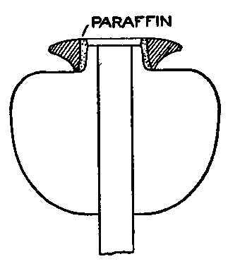
When the rubber washer on the copper flush valve of a soil-basin
tank becomes loose it can be set by pouring a small quantity of
paraffin between the rubber and the copper while the valve is
inverted, care being taken to have the rubber ring centered. This
makes a repair that will not allow a drop of water to leak out of
the tank.
Contributed by Frank Jermin, Alpena, Michigan.
Cleaning Discolored Silver
A very quick way to clean silver when it is not tarnished, but
merely discolored, is to wash the articles in a weak solution of
ammonia water. This removes the black stains caused by sulphur in
the air. After cleaning them with the solution, they should be
washed and polished in magnesia powder or with a cloth. This
method works well on silver spoons tarnished by eggs and can be
used every day while other methods require much time and,
therefore, cannot be used so often.
How to Make a Small Electric Motor
By W. A. Robertson
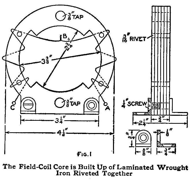
The Field-Coil Core is Built Up of Laminated Wrought Iron Riveted Together
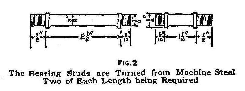
The Bearing Studs are Turned from Machine Steel
Two of Each Length being Required.
The field frame of the motor, Fig. 1, is composed of wrought
sheet iron, which may be of any thickness so that, when several
pieces are placed together, they will make a frame 3/4 in. thick.
It is necessary to layout a template of the frame as shown,
making it 1/16 in. larger than the dimensions given, to allow for
filing to shape after the parts are fastened together. After the
template is marked out, drill the four rivet holes, clamp the
template, or pattern, to the sheet iron and mark carefully with a
scriber. The bore can be marked with a pair of dividers, set at
1/8 in. This will mark a line for the center of the holes to be
drilled with a 1/4-in. drill for removing the unnecessary metal.
The points formed by drilling the holes can be filed to the
pattern size. Be sure to mark and cut out a sufficient number of
plates to make a frame 3/4 in. thick, or even 1/16 in. thicker,
to allow for finishing.
After the plates are cut out and the rivet holes drilled,
assemble and rivet them solidly, then bore it out to a diameter
of 2-3/4 in. on a lathe. If the thickness is sufficient, a slight
finishing cut can be taken on the face. Before removing the field
from the lathe, mark off a space, 3-3/8 in. in diameter, for the
field core with a sharp-pointed tool, and for the outside of the
frame, 4-1/2 in. in diameter, by turning the lathe with the hand.
Then the field can be finished to these marks, which will make it
uniform in size. When the frame is finished so far, two holes,
3-5/8 in. between centers, are drilled and tapped with a 3/8-in.
tap. These holes are for the bearing studs. Two holes are also
drilled and tapped for 1/4-in. screws, which fasten the
holding-down lugs or feet to the frame. These lugs are made of
a piece of 1/8-in. brass or iron, bent at right angles as shown.
The bearing studs are now made, as shown in Fig. 2, and turned
into the threaded holes in the frame. The bearing supports are
made of two pieces of 1/8-in. brass, as shown in the left-hand
sketch, Fig. 3, which are fitted on the studs in the frame. A
5/8-in. hole is drilled in the center of each of these supports,
into which a piece of 5/8-in. brass rod is inserted, soldered
into place, and drilled to receive the armature shaft. These
bearings should be fitted and soldered in place after the
armature is constructed. The manner of doing this is to wrap a
piece of paper on the outside of the finished armature ring and
place it through the opening in the field, then slip the bearings
on the ends of the shaft. If the holes in the bearing support
should be out of line, file them out to make the proper
adjustment. When the bearings are located, solder them to the
supports, and build up the solder well. Remove the paper from the
armature ring and see that the armature revolves freely in the
bearings without touching the inside of the field at any point.
The supports are then removed and the solder turned up in a
lathe, or otherwise finished. The shaft of the armature, Fig. 4,
is turned up from machine steel, leaving the finish of the
bearings until the armature is completed and fastened to the
shaft.
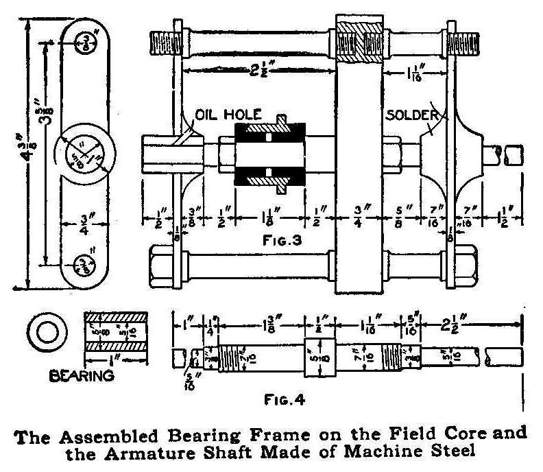
The Assembled Bearing Frame on the Field Core
and the Armature Shaft Made of Machine Steel.
The armature core is made up as follows: Two pieces of wrought
sheet iron, 1/8 in. thick, are cut out a little larger than
called for by the dimensions given in Fig. 5, to allow for
finishing to size. These are used for the outside plates and
enough pieces of No. 24 gauge sheet iron to fill up the part
between until the whole is over 3/4 in. thick are cut like the
pattern. After the pieces are cut out, clamp them together and
drill six 1/8-in. holes through them for rivets. Rivet them
together, and anneal the whole piece by placing it in a fire and
heating the metal to a cherry red, then allowing it to cool in
the ashes. When annealed, bore out the inside to 1-11/16 in. in
diameter and fit in a brass spider, which is made as follows:
Procure a piece of brass, 3/4 in. thick, and turn it up to the
size shown and file out the metal between the arms. Slip the
spider on the armature shaft and secure it solidly with the
setscrew so that the shaft will not turn in the spider when
truing up the armature core. File grooves or slots in the
armature ring so that it will fit on the arms of the spider. Be
sure to have the inside of the armature core run true. When this
is accomplished, solder the arms of the spider to the metal of
the armature core. The shaft with the core is then put in a lathe
and the outside turned off to the proper size. The sides are also
faced off and finished. Make the core 3/4 in. thick. Remove the
core from the lathe and file out slots 1/4 in. deep and 7/16 in.
wide.
The commutator is turned from a piece of brass pipe, 3/4 in.
inside diameter, as shown in Fig. 6; The piece is placed on a
mandrel and turned to 3/4 in. in length and both ends chamfered
to an angle of 60 deg. Divide the surface into 12 equal parts, or
segments. Find the centers of each segment at one end, then drill
a 1/8-in. hole and tap it for a pin. The pins are made of brass,
threaded, turned into place and the ends turned in a lathe to an
outside diameter of 1-1/4 in. Make a slit with a small saw blade
in the end of each pin for the ends of the wires coming from the
commutator coils. Saw the ring into the 12 parts on the lines
between the pins.
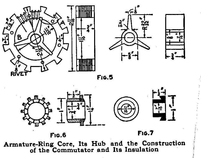
Armature-Ring Core, Its Hub and the Construction of the
Commutator and Its Insulation
The two insulating ends for holding these segments are made of
fiber turned to fit the bore of the brass tubing, as shown in
Fig. 7. Procure 12 strips of mica, the same thickness as the
width of the saw cut made between the segments, and use them as a
filler and insulation between the commutator bars. Place them on
the fiber hub and slip the hub on the shaft, then clamp the whole
in place with the nut, as shown in Fig. 3. True up the commutator
in a lathe to the size given in Fig. 6.
The brush holder is shaped from apiece of fiber, as shown in Fig.
8. The studs for holding the brushes are cut from 5/16-in. brass
rod, as shown in Fig. 9. The brushes consist of brass or copper
wire gauze, rolled up and flattened out to 1/8 in. thick and 1/4
in. wide, one end being soldered to keep the wires in place. The
holder is slipped on the projecting outside end of the bearing,
as shown m Fig. 3, and held with a setscrew.
The field core is insulated before winding with 1/64-in. sheet
fiber, washers, 1-1/8 in. by 1-1/2 in., being formed for the
ends, with a hole cut in them to fit over the insulation placed
on the cores. A slit is cut through from the hole to the outside,
and then they are soaked in warm water, until they become
flexible enough to be put in place. After they have dried, they
are glued to the core insulation.
The field is wound with No. 18 gauge double-cotton-covered magnet
wire, about 100 ft. being required. Drill a small hole through
each of the lower end insulating washers. In starting to wind,
insert the end of the wire through the hole from the inside at A
Fig. 1, and wind on four layers, which will take 50 ft. of. the
wire, and bring the end of the wire out at B. After one coil, or
side, is wound start at C in the same manner as at A, using the
same number of turns and the same length of wire. The two ends
are joined at B.
The armature ring is insulated by covering the inside and brass
spider with l/16-in. sheet fiber. Two rings of 1/16-in sheet
fiber are cut and glued to the sides of the ring. When the glue
is set, cut out the part within the slot ends and make 12 channel
pieces from 1/64-in. sheet fiber, which are glued in the slots
and to the fiber washers. Be sure to have the ring and spider
covered so the wire will not touch the iron or brass.
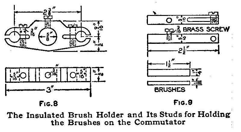
The Insulated Brush Holder and Its Studs for
Holding the Brushes on the Commutator
Each slot of the armature is wound with about 12 ft. of No. 21
gauge double-cotton-covered magnet wire. The winding is started
at A, Fig. 5, by bending the end around one of the projections,
then wind the coil in one of the slots as shown, making 40 turns
or four layers of 10 turns each shellacking each layer as it is
wound. After the coil is completed in one slot allow about 2 in.
of the end to protrude, to fasten to the commutator segment. Wind
the next slot with the same number of turns in the same manner
and so on, until the 12 slots are filled. The protruding ends of
the coils are connected to the pins in the commutator segments
after the starting end of one coils is joined to the finishing
end of the next adjacent. All connections should be securely
soldered.
The whole motor is fastened with screws to a wood base, 8 in.
long, 6 in. wide and 1 in. thick. Two terminals are fastened at
one side on the base and a switch at the other side.
To connect the wires, after the motor is on the stand, the two
ends of the wire, shown at B, Fig. 1, are soldered together. Run
one end of the field wire, shown at A, through a small hole in
the base and make a groove on the under side so that the wire end
can be connected to one of the terminals The other end of the
field wire C is connected to the brass screw in the brass brush
stud. Connect a wire from the other brush stud, run it through a
small hole in the base and cut a groove for it on the under side
so that it can be connected through the switch and the other
terminal. This winding is for a series motor. The source of
current is connected to the terminals. The motor can be run on a
110-volt direct current, but a resistance must be placed in
series with it.
Protecting Tinware
New tinware rubbed over with fresh lard and heated will never rust.
Another Optical Illusion
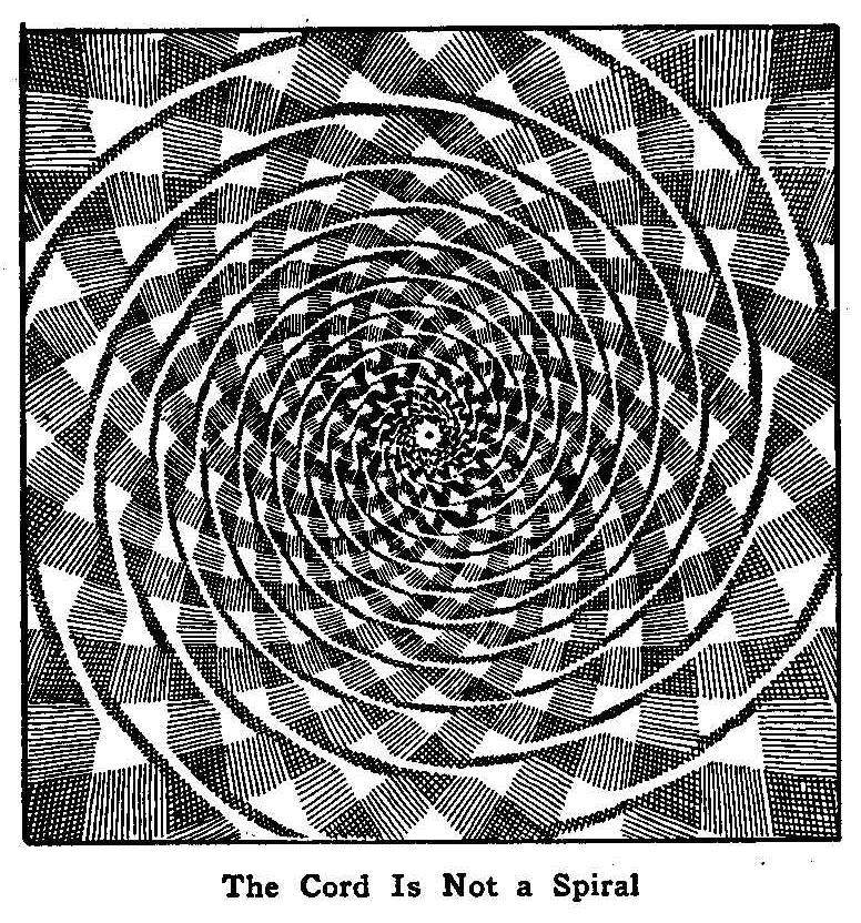
The Cord Is Not a Spiral
After taking a look at the accompanying illustration you will be
positive that the cords shown run in a spiral toward the center,
yet it shows a series of perfect circles of cords placed one
inside the other. You can test this for yourself in a moment with
a pair of compasses, or, still more simply, by laying a point of
a pencil on any part of the cord and following it round. Instead
of approaching or receding from the center in a continuous line,
as in the case of a spiral, you will find the pencil returning to
the point from which it started.
Substitute for Insulating Cleats
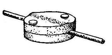
In wiring up door bells, alarms and telephones as well as
experimental work the use of common felt gun wads make a very
good cleat for the wires. They are used in the manner illustrated
in the accompanying sketch. The insulated wire is placed between
two wads and fastened with two nails or screws. If one wad on the
back is not thick enough to keep the wire away from the support,
put on two wads behind and one in front of the wire and fasten in
the same manner as described.
Electrically Operated Indicator for a Wind Vane
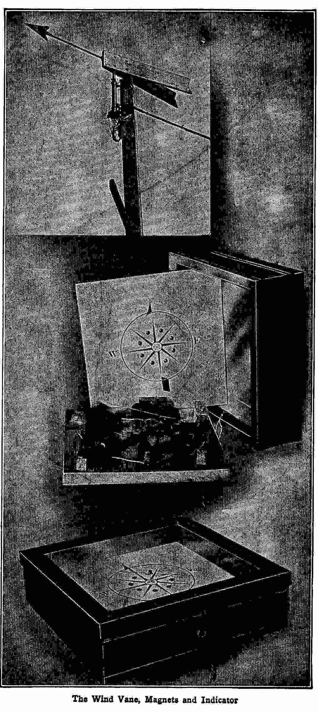
The Wind Vane, Magnets and Indicator
The accompanying photograph shows a wind vane connected with
electric wires to an instrument at considerable distance which
indicates by means of a magnetic needle the direction of the
wind. The bearings of the vane consist of the head of a worn out
bicycle. A 1/2-in. iron pipe extends from the vane and is held in
place by the clamp originally used to secure the handle bar of
the bicycle. In place of the forks is attached an eight-cylinder
gas engine timer which is slightly altered in such a manner that
the brush is at all times in contact, and when pointing between
two contacts connects them both. Nine wires run from the timer,
one from each of the eight contacts, and one, which serves as the
ground wire, is fastened to the metallic body. The timer is set
at such a position that when the vane points directly north, the
brush of the timer makes a connection in the middle of a contact.
When the timer is held in this position the brush will make
connections with each of the contacts as the vane revolves.
The indicating device which is placed in a convenient place in
the house consists of eight 4-ohm magnets fastened upon a 1-in.
board. These magnets are placed in a 10-in. circle, 45 deg.
apart and with their faces pointing toward the center. Covering
these is a thin, wood board upon which is fastened a neatly drawn
dial resembling a mariner’s compass card. This is placed over the
magnets in such a manner that there will be a magnet under each
of the eight principal points marked on the dial. Over this dial
is a magnetic needle or pointer, 6 in. long, perfectly balanced
on the end of a standard and above all is placed a cover having a
glass top. The eight wires from the timer contacts connect with
the outside wires of the eight magnets separately and the inside
wires from the magnets connect with the metal brace which holds
the magnets in place. A wire is then connected from the metal
brace to a push button, two or three cells of dry battery and to
the ground wire in connection with the timer The wires are
connected in such a manner that when the vane is pointing in a
certain direction the battery will be connected in series with
the coil under that part of the dial representing the direction
in which the vane is pointing, thus magnetizing the core of the
magnet which attracts the opposite pole of the needle toward the
face of the magnet and indicating the way the wind is blowing.
The pointer end of the needle is painted black.
If the vane points in such a direction that the timer brush
connects two contacts, two magnets will be magnetized and the
needle will point midway between the two lines represented on the
dial, thus giving 16 different directions. Around the pointer end
of the needle is wound a fine copper wire, one end of which
extends down to about 1/32 in. of the dial. This wire holds the
needle in place when the pointer end is directly over the magnet
attracting it; the magnet causing the needle to “dip” will bring
the wire in contact with the paper dial. Without this attachment,
the needle would swing a few seconds before coming to a
standstill.
The vane itself is easily constructed as can be seen in the
illustration. It should be about 6 ft. long to give the best
results. The magnets used can be purchased from any electrical
store in pairs which are called “instrument magnets.” Any
automobile garage can supply the timer and an old valueless
bicycle frame is not hard to find. The cover is easily made from
a picture frame with four small boards arranged to take the place
of the picture as shown.
The outfit is valuable to a person who is situated where a vane
could not be placed so as to be seen from a window and especially
at night when it is hard to determine the direction of the wind.
By simply pressing the push button on the side of the cover, the
needle will instantly point to the part of the dial from which
the wind is blowing.
Contributed by James L. Blackmer, Buffalo, N. Y.
A Home-Made Floor Polisher
An inexpensive floor polisher can be made as follows: Secure a
wooden box with a base 8 by 12 in. and about 6 in. high, also a
piece of new carpet, 14 by 18 in. Cut 3-in. squares out of the
four corners of the carpet and place the box squarely on it. Turn
three of the flaps of the carpet up and tack them securely to the
sides of the box. Before tacking the fourth side, fold a couple
of newspapers to the right size and shove them in between the
carpet and the bottom of the box for a cushion. Fill the box with
any handy ballast, making it heavy or light, according to who is
going to use it, and securely nail on the top of the box. The
handle can be made from an old broom handle the whole of which
will be none too long. Drive a heavy screw eye into the big end
of the handle and fasten to the polisher by a staple driven
through the eye into the center of the cover, thus making a
universal joint. The size of the box given here is the best
although any size near that, if not too high, will answer the
purpose just as well. The box is pushed or pulled over the floor
and the padded side will produce a fine polish.
How to Make a Lady’s Card-Case
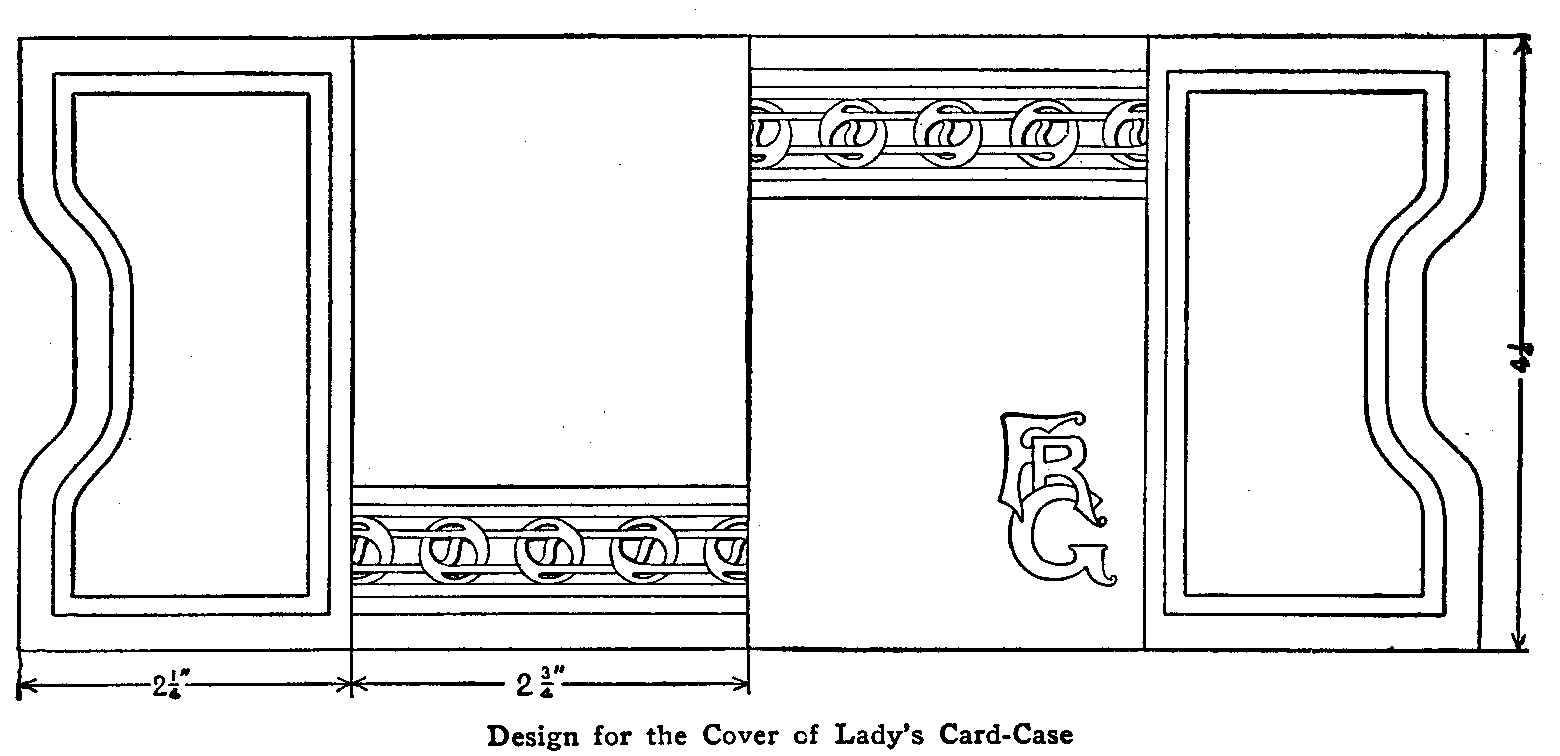
Design for the Cover of Lady’s Card-Case
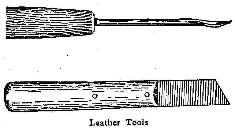
Leather Tools
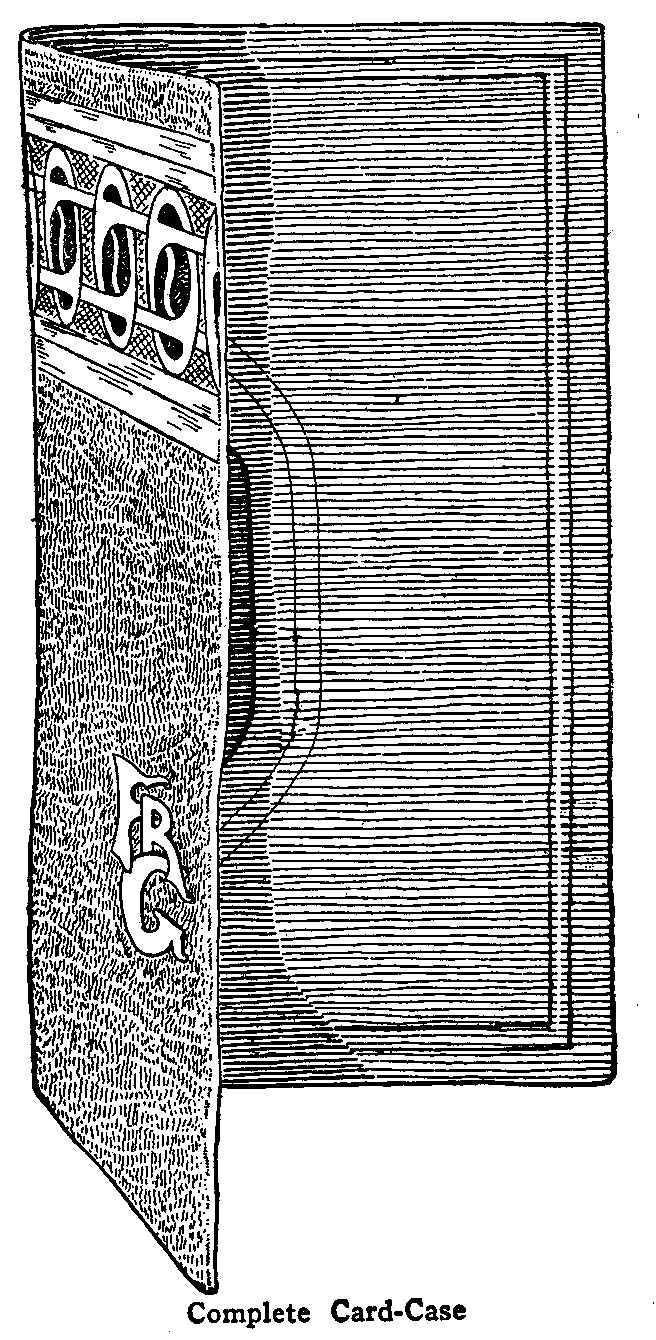
Complete Card Case
A card-case such as is shown here makes a very appropriate
present for any lady. To make it, secure a piece of “ooze” calf
skin leather 4-1/2 by 10-1/2 in. The one shown in the
accompanying picture was made of a rich tan ooze of light weight
and was lined with a grey-green goat skin. The design was
stenciled and the open parts backed with a green silk plush
having a rather heavy nap. The lining of goat skin need not cover
more than the central part-not the flies. A piece 4-1/2 by 5 in.
will be sufficient. A piece of plush 1-1/4 by 6 in. will be
enough for the two sides.
Begin work by shaping the larger piece of leather as shown in the
drawing. Allow a little margin at the top and bottom, however, to
permit trimming the edges slightly after the parts have been
sewed together. A knife or a pair of scissors will do to cut the
leather with, though a special knife, called a chip carving
knife, is most satisfactory.
The next thing is to put in the marks for the outline of the
designs and the borders. A tool having a point shaped as in the
illustration is commonly used. It is called a modeling tool for
leather and may be purchased, or, one can be made from an
ordinary nut pick by taking off the sharpness with fine emery
paper so that it will not cut the leather. To work these
outlines, first moisten the leather on the back with as much
water as it will take and still not show through on the face
side. Place the leather on some level, nonabsorbent surface and
with the tool—and a straightedge on the straight lines—indent
the leather as shown. The easiest way is to place the paper
pattern on the leather and mark on the paper. The indentations
will be transferred without the necessity of putting any lines on
the leather.
With the knife cut out the stencils as shown. Paste the silk
plush to the inner side, being careful not to get any of the
paste so far out that it will show. A good leather paste will be
required.
Next place the lining, fold the flies along the lines indicated
in the drawing. Hold the parts together and stitch them on a
sewing-machine. An ordinary sewing-machine will do if a good
stout needle is used. A silk thread that will match the leather
should be used. Keep the ooze side of the lining out so that it
will show, rather than the smooth side. With the knife and
straightedge trim off the surplus material at the top and bottom
and the book is ready for use.
Home-Made Fire Extinguisher
Dissolve 20 lb. of common salt and 10 lb. of sal ammoniac in 7
gal. of water, and put the solution in thin glass bottles, cork
tightly and seal to prevent evaporation. The bottles should hold
about 1 qt. If a fire breaks out, throw one of the bottles in or
near the flames, or break off the neck and scatter the contents
on the fire. It may be necessary to use several bottles to quench
the flames.
Crutch Made of an Old Broom
An emergency crutch made of a worn-out broom is an excellent
substitute for a wood crutch, especially when one or more
crutches are needed for a short time, as in cases of a sprained
ankle, temporary lameness, or a hip that has been wrenched.
Shorten and hollow out the brush of the broom and then pad the
hollow part with cotton batting, covering it with a piece of
cloth sewed in place. Such a crutch does not heat the arm pit and
there is an elasticity about it not to be had in the wooden
crutch. The crutch can be made to fit either child or adult and
owing to its cheapness, can be thrown away when no longer
needed.
Contributed by Katharine D. Morse, Syracuse, N. Y.
Toy Darts and Parachutes
Dart Parts and Paper Parachute
A dart (Fig. 1) is made of a cork having a tin cap, a needle and
some feathers. The needle is run through the center of the cork A
and a pin or piece of steel is put through the eye of the needle.
Take a quantity of small feathers, B, and tie them together
securely at the bottom. Bore a hole in the center of the cap C,
and fasten the feathers inside of it. Fasten the cap on the cork
and the dart is ready for use. When throwing the dart at a target
stand from 6 to 10 ft. away from it.
The parachute is made by cutting a piece of paper 15 in. square
and tying a piece of string to each corner. The strings should be
about 15 in. long. Tie all four strings together in a knot at the
end and fasten them in the top of a cork with a small tack. It is
best to be as high as possible when flying the parachute as the
air currents will sail it high and fast. Take hold of the
parachute by the cork and run it through the air with the wind,
letting it go at arm’s length.
Contributed by J. Gordon Dempsey, Paterson, N.J.
A Tool for Lifting Can Covers
Made of an Old Fork
A handy tool for prying up varnish paint, syrup and similar can
covers car be made from an old fork filed down to the shape shown
in the illustration. The end is filed to an edge, but not sharp.
Contributed by Ben Grebin, Ashland, Wis.
Keeping Rats from a Chicken Coop
After trying for months to keep the rats from tunneling their way
into my chicken coop by filling in the holes, laying poisoned
meat and meal, setting traps, etc., I devised a simple and
effective method to prevent them from doing harm.
My roosting coop is 5 by 15 ft. There is a 1-in. board all around
the bottom on the inside. I used wire mesh having 1/2-in.
openings and formed it into the shape of a large tray with edges
6 in. high, the corners being wired, and tacked it to the boards.
This not only keeps the rats out, but prevents the chickens from
digging holes, thus helping the rats to enter.
Contributed by John A. Hellwig, Albany, N. Y.
Homemade Telephone Receiver
The receiver illustrated herewith is to be used in connection
with the transmitter described elsewhere in this volume. The body
of the receiver, A, is made of a large wooden ribbon spool. One
end is removed entirely, the other sawed in two on the line C and
a flange, F, is cut on the wood, 1/8 in. wide and 1/16 in. deep.
A flange the same size is made on the end D that was sawed off,
and the outside part tapered toward the hole as shown. The magnet
is made of a 30-penny nail, B, cut to the length of the spool,
and a coil of wire, E, wound on the head end. The coil is 1 in.
long, made up of four layers of No. 22 gauge copper magnet wire,
allowing the ends to extend out about 6 in. The nail with the
coil is then put into the hole of the spool as shown. The
diaphragm C, which is the essential part of the instrument,
should be made as carefully as possible from ferrotype tin,
commonly called tintype tin. The diaphragm is placed between the
flanges on the spool and the end D that was sawed off. The end
piece and diaphragm are both fastened to the spool with two or
three slender wood screws, as shown.
A small wooden or fiber end, G, is fitted with two binding posts
which are connected to the ends of the wire left projecting from
the magnet winding. The binding posts are attached to the line
and a trial given. The proper distance must be found between the
diaphragm and the head of the nail. This can be accomplished by
moving the nail and magnet in the hole of the spool. When the
distance to produce the right sound is found, the nail and magnet
can be made fast by filling the open space with melted sealing
wax. The end G is now fastened to the end of the spool, and the
receiver is ready for use.
How to Clean Jewelry
To cleanse articles of silver, gold, bronze and brass use a
saturated solution of
cyanide of potassium. To clean small
articles, dip each one into the solution and rinse immediately in
hot water; then dry and polish with a linen cloth. Larger
articles are cleaned by rubbing the surface with a small tuft of
cotton saturated in the solution.
As cyanide of potassium is a
deadly poison, care must be taken not to have it touch any sore
spot on the flesh.
Ornamental Iron Flower Stand
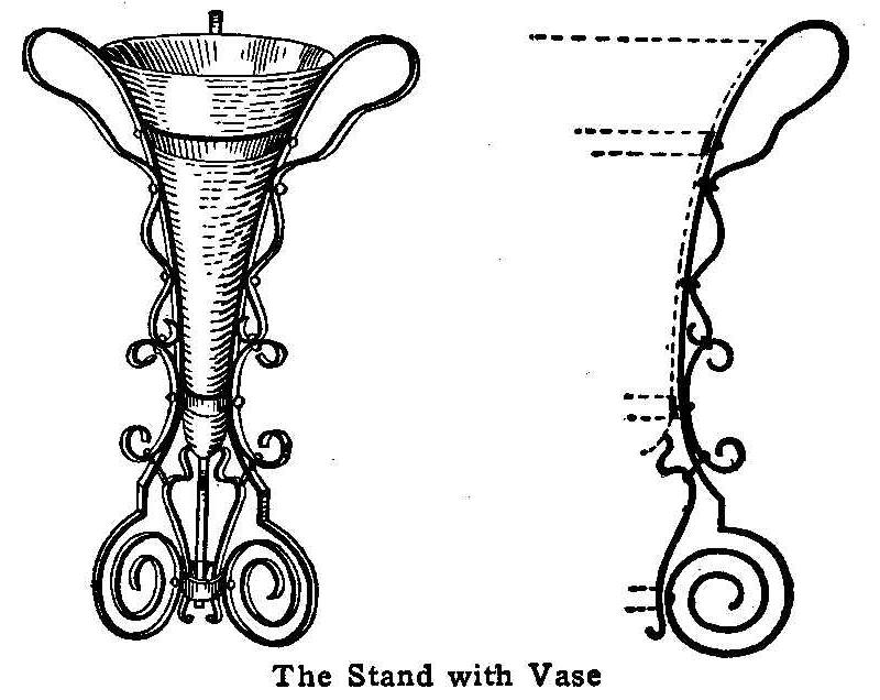
The Stand with Vase
The illustration shows an ornamental iron stand constructed to
hold a glass or china vase. This stand can be made by first
drawing an outline of the vase on a heavy piece of paper. The
vase is to have three supports. The shape of the scrolls forming
each support should be drawn on the paper around the shape of the
vase. A single line will be sufficient, but care must be taken to
get the shapes of the scrolls true. Take a piece of string or,
better still, a piece of small wire, and pass it around the
scroll shape on the paper. This will give the exact length of the
iron required to make the scroll. As sheet metal is used for
making the scrolls, it can be cut in the right lengths with a
pair of tinner’s shears. Take a pair of round-nose pliers, begin
with the smallest scrolls, and bend each strip in shape, using
the flat-nose pliers when necessary to keep the iron straight,
placing it on the sketch from time to time to see that the
scrolls are kept to the shape required. The scrolls are riveted
and bolted together. The supports are fastened together with
rings of strip iron 3/8 in. wide, to which the supports are
fastened with rivets. The metal can be covered with any desired
color of enamel paint.
How to Make a Coin Purse
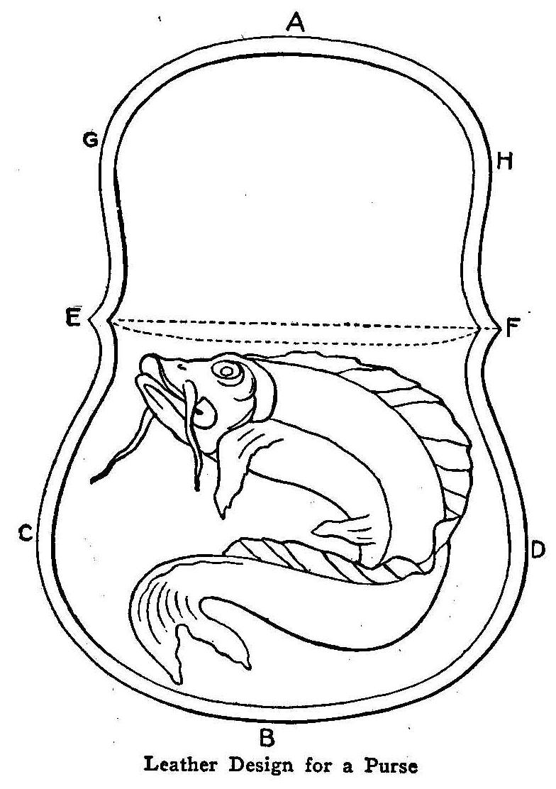
Leather Design for a Purse
The dimensions for a leather coin purse are as follows: from A to
B, as shown in the sketch, 6-3/8 in.; from C to D, 4-1/4 in.;
from E to F, 3-1/2 in. and from G to H, 3-1/4 in. Russian calf
modeling leather is the material used. A shade of brown is best
as it does not soil easily, and does not require coloring.
Cut out the leather to the size of the pattern, then moisten the
surface on the rough side with a sponge soaked in water. Be
careful not to moisten the leather too much or the water will go
through to the smooth side. Have the design drawn or traced on
the pattern. Then lay the pattern on the smooth side of the
leather and trace over the design with the small end of the
leather tool or a hard, sharp pencil. Trace also the line around
the purse. Dampen the leather as often as is necessary to keep it
properly moistened.
After taking off the pattern, retrace the design directly on the
leather to make it more distinct, using a duller point of the
tool. Press or model down the leather all around the design,
making it as smooth as possible with the round side of the tool.
Work down the outside line of the design, thus raising it.
Fold the leather on the line EF. Cut another piece of leather the
size of the side ECBD of the purse, and after putting the wrong
sides of the leather together, stitch around the edge as
designated by the letters above mentioned. Do not make this piece
come quite up to the line EF, so that the coins may be more
easily put in and taken out. About 1 in. from the lines EF on the
piece, stitch in a strip of leather about 1/4 in. wide when
stitching up the purse, through which to slip the fly AGH.
Window Anti-Frost Solution
A window glass may be kept from frosting by rubbing over the
inner surface a solution of 55 parts of glycerine and 1,000 parts
of 60 per cent alcohol. The odor may be improved by adding a
little oil of amber. This solution will also prevent a glass from
sweating in warm weather.
How to Make a Turbine Engine
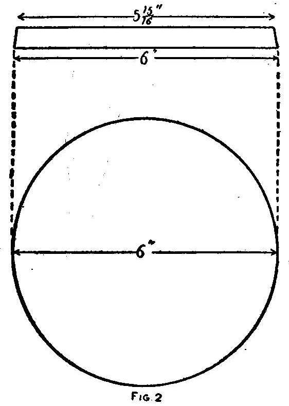
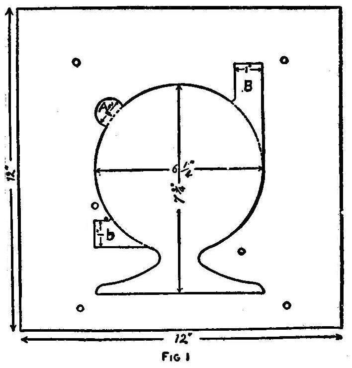
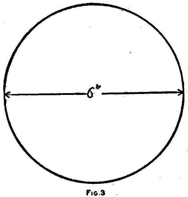
In the following article is described a machine which anyone can
make, and which will be very interesting, as well as useful. It
can be made without the use of a lathe, or other tools usually
out of reach of the amateur mechanic. It is neat and efficient,
and a model for speed and power. Babbitt metal is the material
used in its construction, being cast in wooden molds. The casing
for the wheel is cast in halves—a fact which must be kept in
mind.
First, procure a planed pine board 1 by 12 in. by 12 ft. long.
Cut off six pieces 12 in. square, and, with a compass saw, cut
out one piece as shown in Fig. 1, following the dotted lines,
leaving the lug a, and the projections B and b to be cut out with
a pocket knife. Make the lug 1/4 in. deep, and the projections B,
b, 1/2 in. deep. The entire cut should be slightly beveled.
Now take another piece of wood, and cut out a wheel, as shown in
Fig. 2. This also should be slightly beveled. When it is
finished, place it on one of the square pieces of wood, with the
largest side down, then place the square piece out of which Fig.
1 was cut, around the wheel, with the open side down. (We shall
call that side of a mold out of which a casting is drawn, the
“open” side.) Place it so that it is even at the edge with the
under square piece and place the wheel so that the space between
the wheel and the other piece of wood is an even 1/8 in. all the
way around. Then nail the wheel down firmly, and tack the other
piece slightly.
Procure a thin board 1/4 in. thick, and cut it out as shown in
Fig. 3; then nail it, with pins or small nails, on the center of
one of the square pieces of wood. Fit this to the two pieces just
finished, with the thin wheel down—but first boring a 3/4-in.
hole 1/4 in. deep, in the center of it; and boring a 3/8-in. hole
entirely through at the same place. Now put mold No.1 (for that
is what we shall call this mold) in a vise, and bore six 1/4-in.
holes through it. Be careful to keep these holes well out in the
solid part, as shown by the black dots in Fig. 1. Take the mold
apart, and clean all the shavings out of it; then bolt it
together, and lay it away to dry.
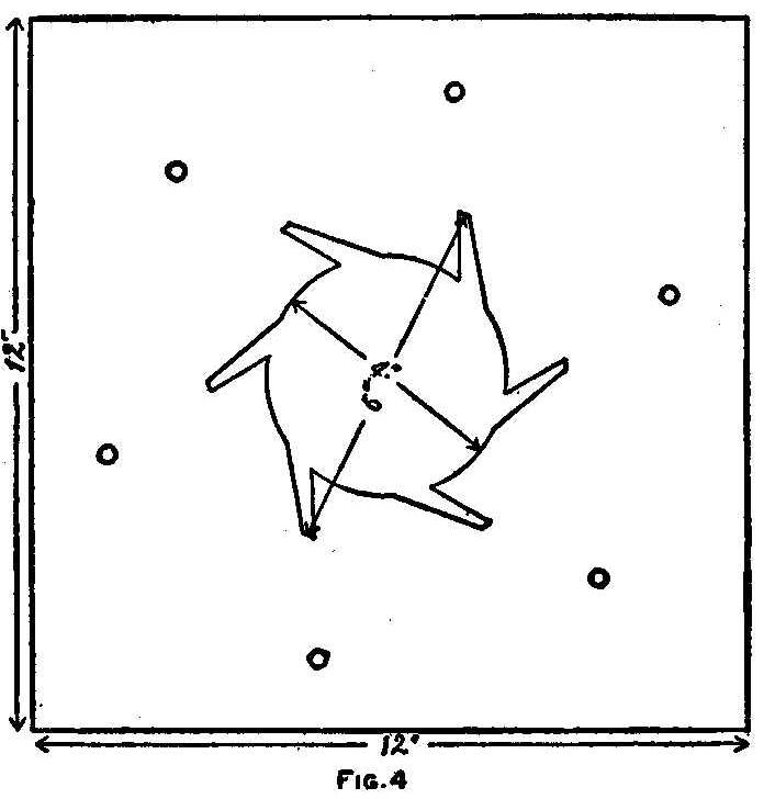
Now take another of the 12-in. square pieces of wood, and cut it
out as shown in Fig. 4, slightly beveled. After it is finished,
place it between two of the 12-in. square pieces of wood, one of
which should have a 3/8-in. hole bored through its center. Then
bolt together with six 1/4-in. bolts, as shown by the black dots
in Fig. 4, and lay it away to dry. This is mold No.2.
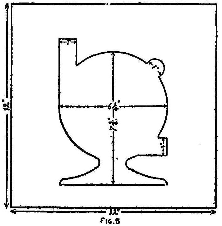
Now take mold No.1; see that the bolts are all tight; lay it on a
level place, and pour babbitt metal into it, until it is full.
Let it stand for half an hour, then loosen the bolts and remove
the casting.
Now cut out one of the 12-in.-square pieces of wood as shown in
Fig. 5. This is the same as Fig. 1, only the one is left-handed,
the other right-handed. Put this together in mold No.1, instead
of the right-handed piece; and run in babbitt metal again. The
casting thus made will face together with the casting previously
made.
Pour metal into mold No.2. This will cast a paddle-wheel, which
is intended to turn inside of the casting already made.
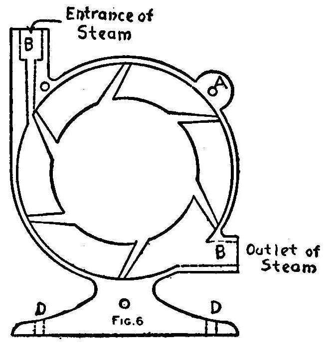
If there should happen to be any holes or spots, where the
casting did not fill out, fill them by placing a small piece of
wood with a hole in it, over the defective part, and pouring
metal in to fill it up.
If you cannot obtain the use of a drill press, take an ordinary
brace, fasten a 3/8-in. drill in it, and bore a hole through the
end of a strip about 2 in. wide and 16 in. long; put the top of
the brace through this hole, and fasten the other end of the
strip to a bench, as shown in illustration. Find the center of
the paddle-wheel, place it under the drill, true it up with a
square; and drill it entirely through. Find the centers of the
insides of the other two castings, and drill them in the same
manner.
A piece of mild steel 5 in. long, and 3/8-in. in diameter must
now be obtained. This is for a shaft. Commencing 1-1/2 in. from
the one end, file the shaft off flat for a distance of 1 in.
Then cut a slot in the paddle-wheel, and place the shaft inside
of the paddlewheel, with the flat part of the shaft turned to
face the slot in the wheel. Pour metal into the slot to key the
wheel on to the shaft.
The paddle-wheel is now ready to be fitted inside of the casing.
It may be necessary to file some of the ends off the paddles, in
order to let the paddle-wheel go into the casing. After it is
fitted in, so that it will turn easily, place the entire machine
in a vise, and bore three 1/4-in. holes, one in the lug, one in
the projections, B, b, and the other in the base, as shown by the
black dots in Fig. 6. Also bore the port-hole in projection B,
and the exhaust hole in projection b, and two 1/4-in. holes at d,
d, Fig. 6. Cut out a piece of gasket and fit it between the two
castings. Then bolt the castings together, screw down, and
connect to the boiler.
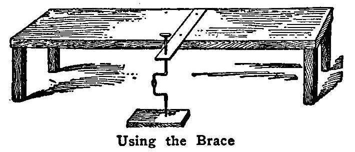
Using the Brace
The reader must either cast a pulley out of babbitt metal, or
else go to a machinist and get a collar turned, with a boss and a
set screw, and with three small screw holes around the edge. Cut
out a small wood wheel and screw the collar fast to it, fasten it
to the shaft of the turbine and turn on the steam. Then take a
knife or a chisel, and, while it is running at full speed, turn
the wheel to the shape desired.
Your turbine engine is now ready for work, and if instructions
have been carefully followed, will do good service.
Painting A Car
When painting the automobile body and chassis be sure to stuff
the oil holes with felt or waste before applying the paint. If
this caution is not observed the holes will become clogged with
paint which will prevent any oil reaching the bearing.
How To Build An Ice Boat
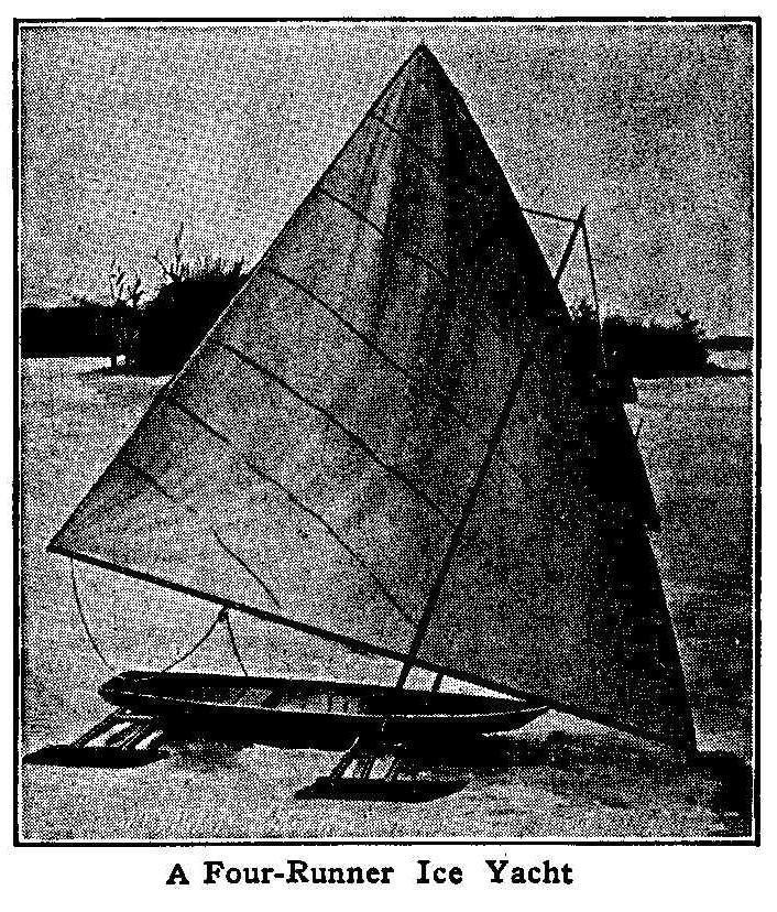
A Four-Runner Ice Yacht
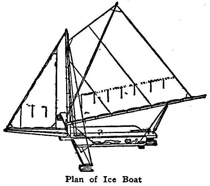
Plan of Ice Boat
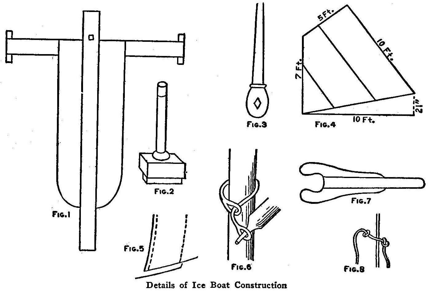
Details of Ice Boat Construction
The ice boat is each year becoming more popular. Anyone with even
small experience in using tools can construct such a craft, and
the pleasure many times repays the effort.
Take two pieces of wood 2 by 6 in., one 6 ft. and the other 8 ft.
long. At each end of the 6-ft. piece and at right angles to it,
bolt a piece of hardwood 2 by 4 by 12 in. Round off the lower
edge of each piece to fit an old skate. Have a blacksmith bore
holes through the top of the skates and screw one of them to each
of the pieces of hardwood. These skates must be exactly parallel
or there will be trouble the first time the craft is used.
Over the middle of the 6-ft. piece and at right angles to it,
bolt the 8-ft. plank, leaving 1 ft. projecting as in Fig. 1.
The rudder skate is fastened to a piece of hardwood 2 by 2 by 12
in. as the runners were fastened. This piece should be mortised 3
by 3 by 4 in. in the top before the skate is put on. Figure 2
shows the rudder post.
A piece of hardwood 1 by 6 by 6 in. should be screwed to the
under side of the 8-ft. plank at the end with the grain running
crosswise. Through this bore a hole 1-1/2-in. in diameter in
order that the rudder post may fit nicely. The tiller, Fig. 3,
should be of hardwood, and about 8 in. long.
To the under side of the 8-ft. plank bolt a piece of timber 2 by
4 by 22 in. in front of the rudder block, and to this cross piece
and the 6-ft. plank nail 8-in. boards to make the platform.
The spar should be 9 ft. long and 2-1/2 in. in diameter at the
base, tapering to 1-1/2 in. at the top. This fits in the square
hole, Fig. 1. The horn should be 5-1/2 ft. long, 2 by 3 in. at
the butt and 1 in. at the end.
Figure 4 gives the shape and dimensions of the mainsail which can
be made of muslin. Run the seam on a machine, put a stout cord in
the hem and make loops at the corners.
Figure 6 shows the way of rigging the gaff to the spar. Figure 7
shows the method of crotching the main boom and Fig. 8 a reef
point knot, which may come in handy in heavy winds.
Make your runners as long as possible, and if a blacksmith will
make an iron or steel runner for you, so much the better will be
your boat.
Electric Rat Exterminator
Electric Rat Trap
Some time ago we were troubled by numerous large rats around the
shop, particularly in a storehouse about 100 ft. distant, where
they often did considerable damage. One of the boys thought he
would try a plan of electrical extermination, and in order to
carry out his plan he picked up an old zinc floor plate that had
been used under a stove and mounted a wooden disk 6 in. in
diameter in the center. On this disk he placed a small tin pan
about 6 in. in diameter, being careful that none of the fastening
nails made an electrical connection between the zinc plate and
the tin pan.
This apparatus was placed on the floor of the warehouse where it
was plainly visible from a window in the shop where we worked and
a wire was run from the pan and another from the zinc plate
through the intervening yard and into the shop. A good sized
induction coil was through connected with these wires and about
six dry batteries were used to run the induction coil whenever a
push button was manipulated.
It is quite evident that when a rat put its two fore feet on the
edge of the pan in order to eat the mush which it contained, that
an electrical connection would be made through the body of the
rat, and when we pushed the button up in the shop the rat would
be thrown 2 or 3 ft. in the air and let out a terrific squeak.
The arrangement proved quite too effective, for after a week the
rats all departed and the boys all regretted that their fun was
at an end.
Contributed by John D. Adams, Phoenix, Ariz.
How to Make a Simple Fire Alarm
Simple Fire Alarm
A fire alarm which is both inexpensive and simple in construction
is shown in the illustration. Its parts are as follows:
A, small piece of wood; B, block of wood nailed to A; S S, two
pieces of sheet brass about 1/4 in. wide, bent into a hook at
each end; P, P, binding-posts fastening the springs S S, to block
B, so that they come in contact at C. W is a piece of wax crayon
just long enough to break the contact at C when inserted as shown
in the illustration.
When these parts have been put together in the manner described,
connect the device in circuit with an electric bell, and place it
behind a stove. When the stove becomes too hot the wax will melt
at the ends, allowing the springs to contact at C, and the alarm
bell will ring.
Contributed by J. R. Comstock, Mechanicsburg, Pa.
To Build a Merry-Go-Round
Home-Made Merry-Go-Round
This is a very simple device, but one that will afford any amount
of amusement. The center post rests in an auger hole bored in an
old stump or in a post set in the ground. The stump makes the
best support. The center pole should be 10 ft. high. An old wheel
is mounted at the top of the pole, and the pole works in the
wheel as an axle, says the American Boy. The wheel is anchored
out by several guy wires. The seat arms may be any length
desired. A passenger rides in each seat and the motorman takes
his station at the middle.
Arbor Wheels
Emery wheel arbors should be fitted with flanges or washers
having a slight concave to their face.
Novelty Clock for the Kitchen
The Clock with Holder
An inexpensive and easy way to make an unique ornament of a clock
for kitchen use is to take an old alarm clock or a new one if
preferred, and make it into a clock to hang on the wall. Take the
glass, dial and works out of the shell and cut some pieces out of
the metal so that when the pieces left are turned back it will
have the appearance as in Fig. 1. Then get a 10-cent frying pan,
6 in. in diameter, and drill a hole in the center so the shaft
for the hands will easily pass through and extend out far enough
to replace the two hands. Put the works back in the metal shell
and solder it to the frying pan by the pieces turned out as in
Fig. 2. Gild the pan all over, including the handle, and print
black figures in the small circles. Calendar figures can be
pasted on small circles and these pasted on the frying pan. The
parts can be divided into minutes with small lines the same as
shown in the drawing. Make new hands that are long enough to
reach the figures from sheet brass or tin and paint them black.
Contributed by Carl P. Herd, Davenport, Iowa
How to Make a Small Silver Plating Outfit
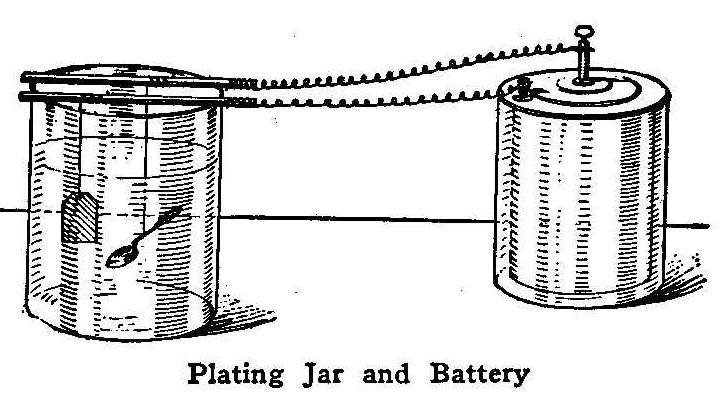
Plating Jar and Battery
Take an ordinary glass fruit jar or any other receptacle in
glass, not metal, which will hold 1 qt. of liquid and fill it
with rain or distilled water and then add 3/4 oz. of silver
chloride and 1-1/2 oz. of c.p.
potassium cyanide. Let this
dissolve and incorporate well with the water before using. Take
an ordinary wet battery and fasten two copper wires to the
terminals and fasten the other ends of the wires to two pieces of
heavy copper wire or 1/4-in. brass pipe. The wires must be well
soldered to the brass pipe to make a good connection. When the
solution is made up and entirely dissolved the outfit is ready
for plating.
Procure a small piece of silver, a silver button,
ring, chain or anything made entirely of silver and fasten a
small copper wire to it and hang on the brass pipe with
connections to the carbon of the battery. Clean the article to be
plated well with pumice and a brush saturated in water. When
cleaning any article there should be a copper wire attached to
it. Do not touch the article after you once start to clean it, or
the places touched by your fingers will cause the silver plate to
peel off when finished. When well scoured, run clear, cold water
over the article and if it appears greasy, place in hot water.
When well cleaned place in the plating bath and carefully watch
the results. If small bubbles come to the surface you will know
that you have too much of the anode or the piece of silver
hanging in the solution and you must draw out enough of the piece
until you can see no more bubbles. Leave the piece to be plated
in the solution for about one-half hour, then take the article
out and with a tooth brush and some pumice, clean the yellowish
scum off, rinse in clear water and dry in sawdust. When
thoroughly dry, take a cotton flannel rag and some polishing
powder and polish the article. The article must have a fine
polish before plating if it is desired to have a finely polished
surface after the plate is put on. In order to see if your
battery is working, take a small copper wire and touch one end to
the anode pipe and the other end to the pipe holding the article
to be plated. When these two parts touch there will be a small
spark. Always take the zincs out of the solution when not in use
and the batteries will last longer. This description applies
only to silver plating. Articles of
lead, pewter, tin or any soft
metal cannot be silver plated unless the article is first copper
plated.
Removing a Tight-Fitting Ring from a Finger
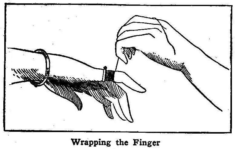
Wrapping the Finger
When a ring cannot be removed easily from the finger, take a
string or thread and draw one end through between the ring and
the flesh. Coil the other end of the string around the finger
covering the part from the ring to and over the finger joint.
Uncoil the string by taking the end placed through the ring and
at the same time keep the ring close up to the string. In this
way the ring can be easily slipped over the knuckle and off from
the finger.
Contributed by J. K. Miller, Marietta, Penn.
A Photographic Jig-Saw Puzzle
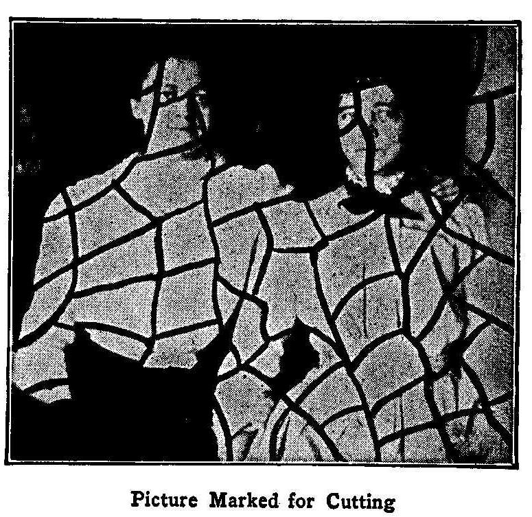
Picture Marked for Cutting
Take any photographic print and mount it on heavy cardboard, or,
if you have a jig saw, a thin smooth wood board and mark out
various shaped pieces as shown in the accompanying cut. If the
picture is mounted on cardboard, the lines can be cut through
with a sharp pointed knife. If you have a jig saw, you can make a
bromide enlargement from the negative you have selected and
mount the print on a smooth board that is not too thick. This
wood-mounted picture can be sawed out making all shapes of
blocks, which forms a perfect jig-saw puzzle.
Contributed by Erich Lehmann, New York City.
Rolling Uphill Illusion
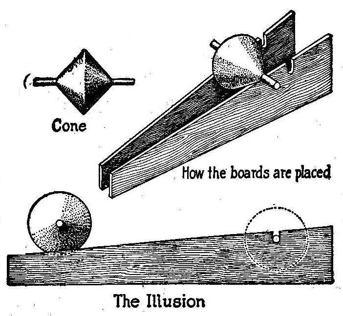
The Illusion
This interesting as well as entertaining illusion, can be made by
anyone having a wood-turning lathe. A solid, similar to two cones
placed base to base, is accurately turned in a lathe, the sides
sloping to an angle of 45 deg. The spindle can be turned out of
the solid at the same time as the cone; or, after turning the
cone, drive an iron or wood shaft through the center making a
tight fit.
The boards for the track are made with a sloping edge on which
the cone is to roll. This slope will depend on the diameter of
the cone, which can be any size from 3 to 12 in. The slope should
not be too flat, or the cone will not roll, and it should be such
that the one end will be higher than the other by a little less
than half the diameter of the cone. Thus it will be seen that the
diameter of the cone determines the length of the slope of the
tracks. A notch should be cut in the tracks, as indicated, for
the shaft to drop into at the end of the course.
The lower end of the tracks are closed until the high edge of the
cone rests upon the inside edges of the tracks and the high end
spread sufficiently to take the full width of the cone and to
allow the shaft to fall into the notches. When the cone and
tracks are viewed from the broadside the deception will be more
perfect, and will not be discovered until the construction of the
model is seen from all sides. Should it be difficult to make the
cone from wood, a good substitute can be made from two
funnels.
Contributed by I. G. Bayley, Cape May Point, N.J.
Maple Leaf
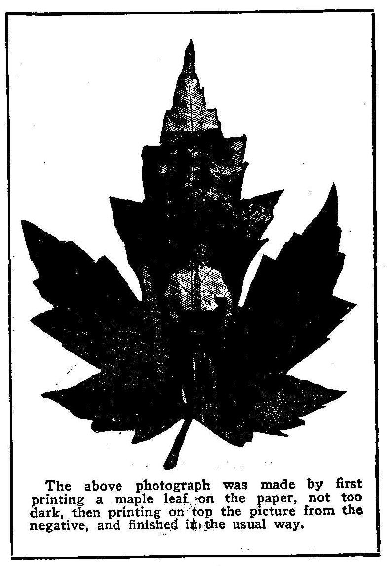
The above photograph was made by first printing a mapleleaf on
the paper, not too dark, then printing on top of the picture from
the negative, and finished in the usual way.
Annealing Chisel Steel
Persons who have occasion to use tool or carbon steel now and
then and do not have access to an assorted stock of this material
find that the kind most readily obtained at the hardware store is
the unannealed steel known as chisel steel. Machining or filing
such steel is exceedingly slow and difficult, besides the
destruction of tools; as a matter of fact this steel is intended
for chisels, drills, and like tools which require only forging
and filing. If this steel is annealed, it can be worked as easily
as the more expensive annealed steel.
Annealing may be done by heating the steel to a cherry red, not
any more, and burying it in a box of slaked lime, where it is
allowed to remain until all the heat is gone. If well done, the
metal will be comparatively soft and in a condition to machine
easily and rapidly. In lieu of lime, bury in ashes, sand, loam,
or any substance not inflammable, but fine enough to closely
surround the steel and exclude the air so that the steel cools
very slowly.
If possible, keep the steel red hot in the fire several hours,
the longer the better. In certain processes, like that of file
manufacturing, the steel blanks are kept hot for 48 hours or
more. Where it is impossible to wait so long as the foregoing
method takes, then a cold water anneal may be used with less
time. This method consists of heating the work as slowly and
thoroughly as the time will permit, then removing the steel from
the fire and allowing it to cool in the air until black and then
quenching in water.
In addition to softening the steel, annealing benefits the metal
by relieving strains in the piece. Should a particularly accurate
job be called for, the steel should be annealed again after the
roughing cuts have been taken and before machining to the final
size. This will insure a true job and diminishes the danger of
spring in the final hardening.
Contributed by Donald A. Hampson, Middletown, N. Y.
How to Make a Post Card Holder
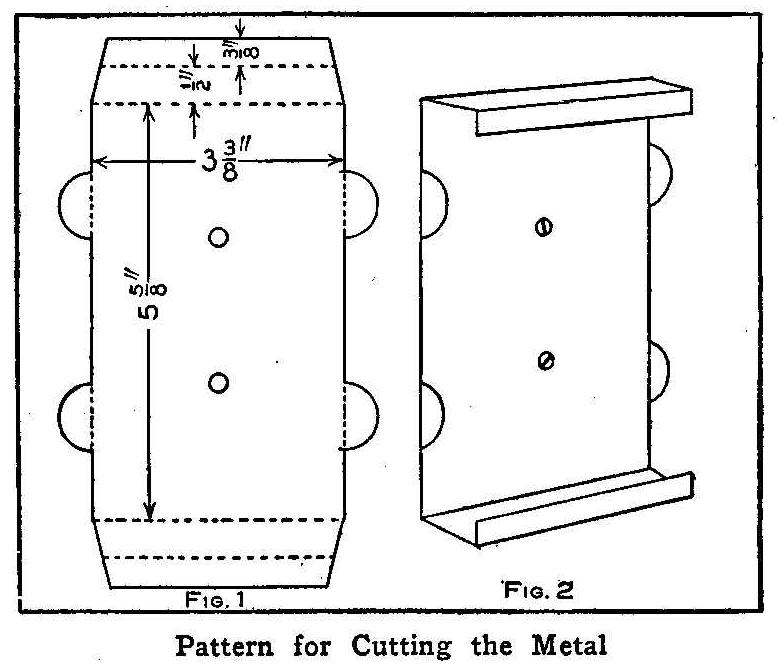
Pattern for Cutting the Metal
This holder is designed to lay flat on the counter or to stack
one on top of the other, keeping each variety of cards separate,
or a number of them can be fastened on any upright surface to
display either horizontal or vertical cards.
The holders can be made from sheet tin, zinc, brass or aluminum.
The dimensions for the right size are given in Fig. 1; the dotted
line showing where the bends are made. The completed holder is
shown in Fig. 2 as fastened to a wall.
Contributed by John F. Williamson, Daytona, Fla.
Unused Paint
Do not allow paint that is left over from a job to stand
uncovered. The can should be tightly sealed and the paint will
be found suitable for use for several days.
Perfume-Making Outfit
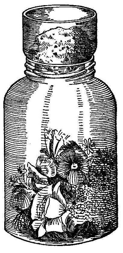
The real perfume from the flowers is not always contained in the
liquid purchased for perfume. The most expensive perfume can be
made at home for less than 10 cents an ounce. The outfit
necessary is a large bottle or glass jar with a smaller bottle to
fit snugly into the open mouth of the large one. Secure a small
piece of very fine sponge and wash it clean to thoroughly remove
all grit and sand. Saturate the sponge with pure olive oil, do
not use strong oil, and place it inside of the smaller bottle.
Fill the large bottle or jar with flowers, such as roses,
carnations, pansies, honeysuckles or any flower having a strong
and sweet odor. Place the small bottle containing the sponge
upside down in the large one, as shown in the illustration.
The bottle is now placed in the sun and kept there for a day and
then the flowers are removed and fresh ones put in. Change the
flowers each day as long as they bloom. Remove the sponge and
squeeze out the oil. For each drop of oil add 2 oz. of grain
alcohol. If stronger perfume is desired add only 1 oz. alcohol to
each drop of oil.
Home-Made Duplicator for Box Cameras
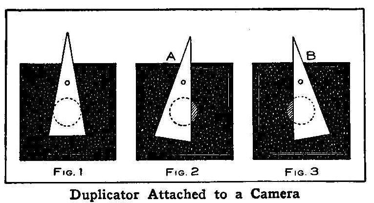
Duplicator Attached to a Camera
The projecting tube of the lens on a hand camera can be easily
fitted with a duplicator while the box camera with its lens set
on the inside and nothing but a hole in the box does not have
such advantages. A small piece of heavy cardboard can be made to
produce the same results on a box camera as a first-class
duplicator applied to a hand camera. The cardboard is cut
triangular and attached to the front end of the camera as shown
in Fig. 1 with a pin about 1 in. above the lens opening. A rubber
band placed around the lower end of the cardboard and camera
holds the former at any position it is placed. A slight pressure
of the finger on the point A, Fig. 2, will push the cardboard
over and expose one-half of the plate and the same pressure at B,
Fig. 3, will reverse the operation and expose the other one-half.
Pins can be stuck in the end of the camera on each side of the
lens opening at the right place to stop the cardboard for the
exposure. With this device one can duplicate the picture of a
person on the same negative.
Contributed by Maurice Baudier, New Orleans, La.
Optical Illusions
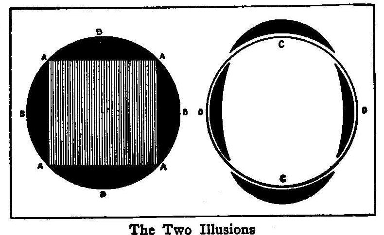
The Two Illusions
The accompanying sketch shows two optical illusions, the first
having a perfect circle on the outside edge appears to be
flattened at the points A, and the arcs of the circle, B, appear
to be more rounding. In the second figure the circle appears to
have an oval form with the distance from C to C greater than from
D to D. A compass applied to the circles in either figures will
show that they are perfectly round.
Contributed by Norman S. Brown, Chippewa Falls, Wis.
Use of Kerosene in Polishing Metals
Anyone who has polished a flat iron or steel surface with emery
cloth knows how soon the cloth gums and fills up. The cloth in
this condition will do little or no cutting. A simple remedy for
this trouble is to use kerosene on the surface. The oil floats
away a large part of the gumming substance and leaves the emery
cloth sharp and clean to do the best work, also, it seems to act
as a lubricant to keep particles of metal from collecting on the
cloth and scratching or digging in the surface of the metal. A
very light lard oil is equally good for this purpose, but not
always easily obtained. A surface polished where oil or kerosene
is used does not rust so easily as one polished dry, for the
reason that a little oil remains on the metal.
Kerosene is the best to use on oil stones, being better than
heavier oil. This oil readily floats away all particles of the
feather edge that are liable to become loosened and forced into
the stone. These particles of metal when stuck to the stone are
the cause of spoiling it, as well as nicking the tools that are
being sharpened. Keep the surface of the stone well oiled at all
times to make the cutting free.
Contributed by Donald A. Hampson, Middletown, N. Y.
How to Make Lamps Burn Brightly
For a good, steady light there is nothing better than a lamp, but
like most everything it must have attention. After cleaning well
and fitting it, place a small lump of camphor in the oil vessel.
This will greatly improve the light and make the flame clearer
and brighter. If there is no camphor at hand add a few drops of
vinegar occasionally.
A Practical Camera for Fifty Cents
By C. H. Claudy
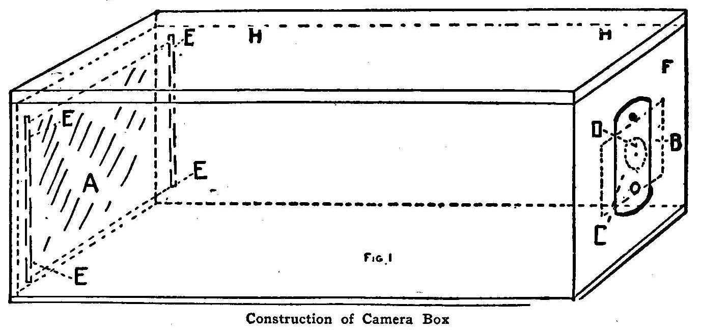
Construction of Camera Box
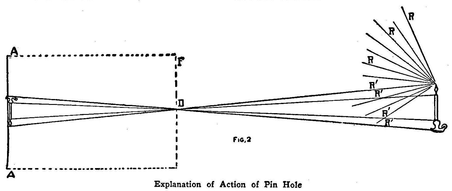
Explanation of Action of Pin Hole
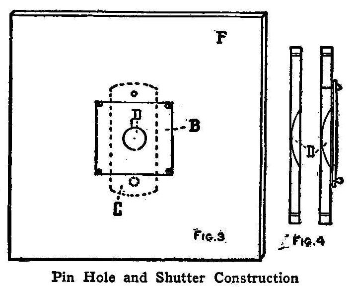
Pin Hole and Shutter Construction
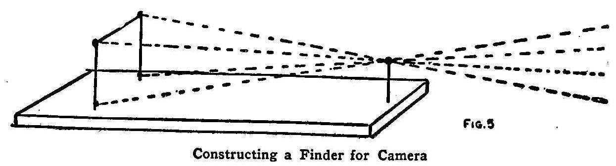
Constructing a Finder for Camera
I say for fifty cents, but really this is an outside estimate. If
you possess a few tools and the rudiments of a shop, by which is
meant a few odds and ends of screws, brass and nails, you can
really make this camera for nothing.
The camera box is the first consideration, and for this a cigar
box answers every purpose. It is better to use one of the long
boxes which contain a hundred cigars and which have square ends.
This box should be cut down, by means of a saw and a plate, until
the ends are 4 in. square. Leave the lid hinged as it is when it
comes. Clean all the paper from the outside and inside of the
box—which may be readily done with a piece of glass for a
scraper and a damp cloth—and paint the interior of the box a
dead black, either with carriage makers’ black or black ink.
Now bore in the center of one end a small hole, 1/4 in. or less
in diameter. Finally insert on the inside of the box, on the
sides, two small strips of wood, 1/8 by 1/4 in. and fasten them
with glue, 1/8 in. from the other end of the box. Examine Fig. 1,
and see the location of these strips, which are lettered EE.
Their purpose is to hold the plate, which may be any size desired
up to 4 in. square. Commercially, plates come 3-1/2 by 3-1/2
in., or, in the lantern slide plate, 3-1/4 by 4 in. If it is
desired to use the 3-1/2 by 3-1/2 in. plates, which is advised,
the box should measure that size in its internal dimensions.
We now come to the construction of the most essential part of the
camera—the pin hole and the shutter, which take the place of the
lens and shutter used in more expensive outfits. This
construction is illustrated in Fig. 4. Take a piece of brass,
about 1/16-in. thick and 1-1/2 in. square. Bore a hole in each
corner, to take a small screw, which will fasten it to the front
of the camera. With 1/4-in. drill bore nearly through the plate
in the center, but be careful that the point of the drill does
not come through. This will produce the recess shown in the first
section in Fig. 4. Now take a No. 10 needle, insert the eye end
in a piece of wood and very carefully and gently twirl it in the
center of the brass where it is the thinnest, until it goes
through. This pin hole, as it is called, is what produces the
image on the sensitive plate, in a manner which I shall presently
describe. The shutter consists of a little swinging piece of
brass completely covering the recess and pin hole, and provided
with a little knob at its lower end. See Fig. 3, in which F is
the front of the camera, B the brass plate and C the shutter.
This is also illustrated in the second cross section in Fig. 4.
In the latter I have depicted it as swung from a pivot in the
brass, and in Fig. 3 as hung from a screw in the wood of the
front board; either construction will be effective.
Lastly, it is necessary to provide a finder for this camera in
order to know what picture you are taking. Make a little frame of
wire, the size of the plate you are using, and mount it upright
(see Fig. 5) on top of the camera as close to the end where the
pin hole is as you can. At the other end, in the center, erect a
little pole of wire half the height of the plate. If now you look
along the top of this little pole, through the wire frame and see
that the top of the little pole appears in the center of the
frame, everything that you see beyond will be taken on the plate,
as will be made plain by looking at the dotted lines in Fig. 5,
which represents the outer limits of your vision when confined
within the little frame.
When you want to use this camera, take it into an absolutely dark
room and insert a plate (which you can buy at any supply store
for photographers) in the end where the slides of wood are, and
between them and the back of the box. Close the lid and secure it
with a couple of rubber bands. See that the little shutter covers
the hole. Now take the camera to where you wish to take a
photograph, and rest it securely on some solid surface. The
exposure will be, in bright sunlight and supposing that your
camera is 10 in. long, about six to eight seconds. This exposure
is made by lifting the little brass shutter until the hole is
uncovered, keeping it up the required time, and then letting it
drop back into place. It is important that the camera be held
rigid during the exposure, and that it does not move and is not
jarred—otherwise the picture will be blurred. Remove the plate
in the dark room and pack it carefully in a pasteboard box and
several wrappings of paper to protect it absolutely from the
light. It is now ready to be carried to some one who knows how to
do developing and printing.
To explain the action of the pin hole I would direct attention to
Fig. 2. Here F represents the front of the camera, D the pinhole,
AA the plate and the letters RR, rays from a lighted candle.
These rays of course, radiate in all directions, an infinite
multitude of them. Similar rays radiate from every point of the
object, from light reflected from these points. Certain of these
rays strike the pin hole in the front of the camera, represented
here by RRRR. These rays pass through the pin hole, and as light
travels only in straight lines, reach the plate AA, forming an
inverted image of the object, in this case a candle in a
candlestick. Millions of rays are given off by every point in
every object which is lighted by either direct or reflected
light. To all practical purposes only one of these rays from each
point in an object can pass through a minute opening like a pin
hole. This being so, any screen which interrupts these selected
rays of light will show upon it a picture of the object, only
inverted. If that screen happens to be a photographically
sensitive plate, which is protected from all other light by being
in a dark box, upon it will be imprinted a photographic image
which can be made visible by the application of certain
chemicals, when it becomes a negative, from which may be printed
positives. This camera is not a theoretical possibility, but an
actual fact. I have made and used one successfully, as a
demonstration of pin-hole photography.
Use for an Old Clock
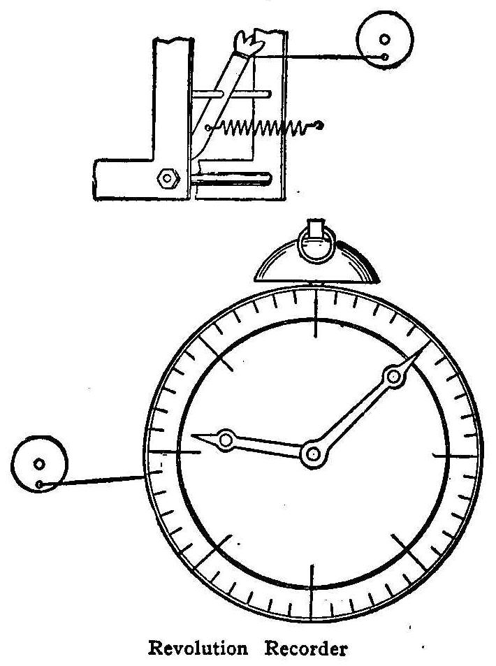
Revolution Recorder
Remove the hair spring of the clock, and fasten a spring to one
end of the pawl and a small wire to the other end. Make a slit in
the case of the clock opposite the pawl. Fasten the spring on the
outside in any convenient way and pass the wire through the slit
to an eccentric or other oscillating body.
To make the dial, paste a piece of paper over the old dial, pull
the wire back and forth one hundred times, and make a mark where
the minute hand stops. Using this for a unit divide up the whole
dial. The hour hand has an inner circle of its own. Put the alarm
hand at a little before twelve and wind the alarm. When the alarm
is unwound the hour hand starts on a new trip. The clock I used
was put on an amateur windmill and when the hour hand went around
once 86,400 revolutions or jerks on the wire were made, while the
minute hand recorded one-twelfth of this number, or 7,200.
Contributed by Richard H. Ranger, Indianapolis, Ind.
Renewing Dry Batteries
Dry batteries, if not too far gone, can be renewed by simply
boring a small hole through the composition on top of each carbon
and pouring some strong salt water or sal ammoniac solution into
the holes. This kink is sent us by a reader who says that the
process will make the battery nearly as good as new if it is not
too far gone beforehand.
Saving a Brush
If a round brush spreads too much, slip a rubber band over the
upper part of the bristles.
How to Make a Simple Burglar Alarm
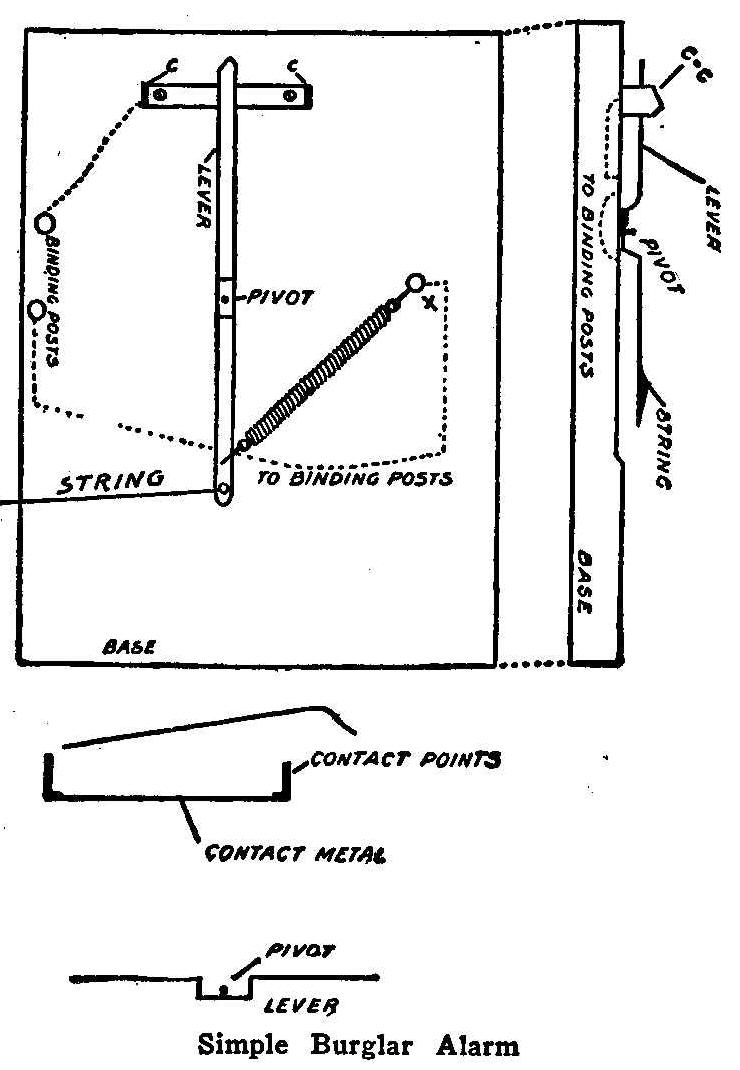
Simple Burglar Alarm
Take a piece of any wood about 6 by 8 in. for the base. This may
be finished in any way desired. For the contact points use brass
or any sheet metal which will be satisfactory. Take a piece about
2-1/2 or 3 in. in length and bend the ends up about 1/2 in. in a
vertical position as shown. Fasten this to the top of the board
using screws or nails. Under this strip of metal fasten a copper
wire which can be connected to a binding-post on the board if
desired. Take another piece of metal about 4-1/2 in. in length
and make a lever of it in the shape shown in the diagram. Fasten
this so that one end of it will swing freely, but not loosely
between the ends of the other piece marked C-C. Near the end
fasten a spiral spring, S, which can be obtained almost anywhere.
Fasten the end of this to the screw marked X. Also fasten to this
screw a copper wire leading to the binding-post. In the lower end
of the lever make a small hole to fasten a string through.
This string may be fastened across a door or window and any
movement of it will pull it to the contact point on the right. If
the string is cut or broken the spring will pull the lever to the
contact point on the left and thus complete the circuit. If the
string is burned it will also act as a fire alarm.
How to Fit Corks
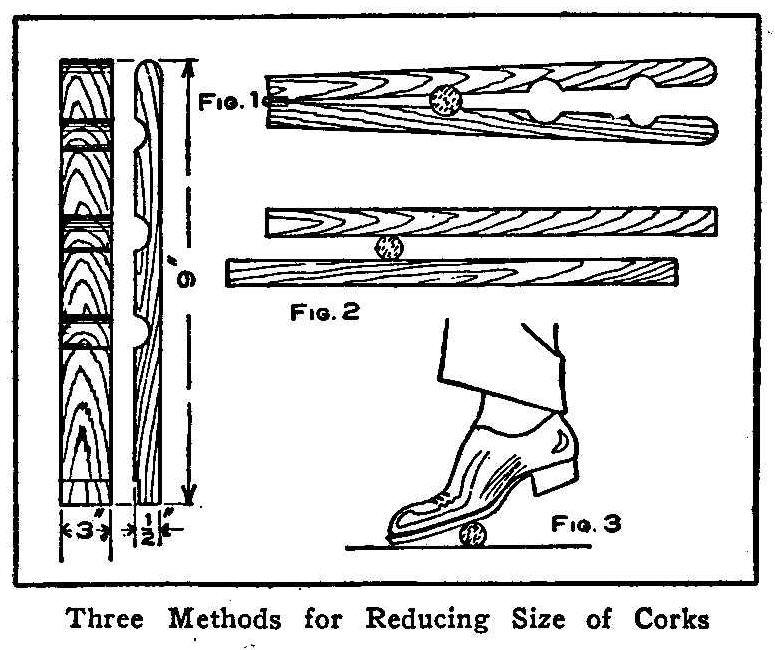
Three Methods for Reducing Size of Corks
Occasionally odd-sized bottles are received in stores which
require corks cut to fit them. No matter how sharp a knife may
be, it will leave some sharp edges after cutting the cork, which
will cause leakage. The illustration shows three very effective
methods of reducing the size of corks. The one shown in Fig. 1 is
made from two pieces of 1/2-in. wood fastened together at one
end with a common hinge. Two or three grooves are cut cross-wise
in sizes desired. The cork is put into the groove and both pieces
are pressed together, which will make the cork smaller.
Rolling the cork between two flat surfaces (Fig. 2) is simple and
almost as good as pressing in the grooves. A cork rolled on the
floor (Fig. 3) is a quick and effective way. A slower and equally
as good way is to soak the cork in hot water for a short time.
Contributed by L. Szerlip, Brooklyn, N. Y.
Right Handed Engine
Standing at the cylinder end and looking toward the flywheel of
an engine, the wheel will be at the right if the engine is
right-hand.
Home-Made Crutch
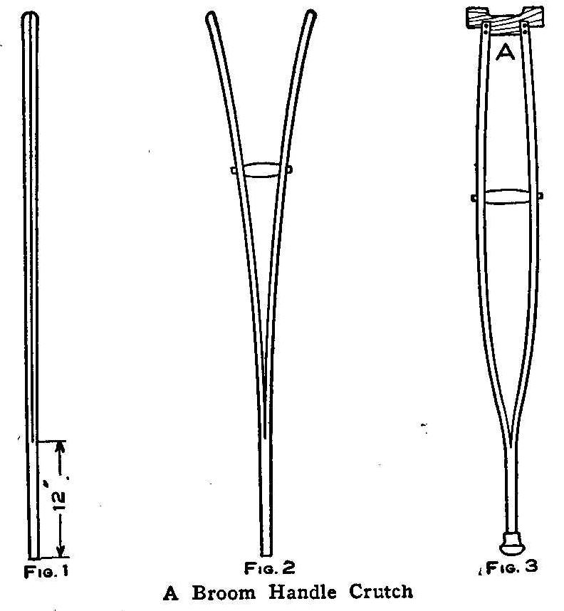
A Broom Handle Crutch
While a fractured bone was healing in the limb of my boy he
needed a pair of crutches and not being able to secure the right
length, I set about to make the crutches from two broom handles.
I split the handles to within 1 ft. of the end (Fig. 1) with a
rip saw, and then stuck them in a barrel of water for three days
to make the wood pliable for bending. A grip for each stick was
made as long as the hand is wide and a hole bored through the
center the size of a No. 10 gauge wire. These grips were placed
between the two halves of each stick at the right distance for
the length of the boy’s arm and a wire run through both split
pieces and the handle then riveted as shown in Fig. 2. Another
piece was cut as shown at A, Fig. 3, and nailed to the upper ends
of each half of the broom handle.
Contributed by Geo. P. Grehore, Nashville, Tenn.
Home-Made Necktie Holder
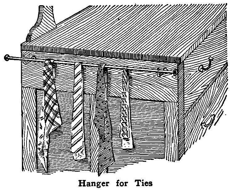
Hanger for Ties
The gas bracket is considered a good place to hang neckties, even
if it does crowd them together. The illustration shows a better
method, a curtain rod attached to one end of a bureau. Two
long-shanked, square-hooked screws should be used, so they may be
screwed beneath and close up to the projecting top. When removed
they will leave no disfiguring holes.
Contributed by C. W. Neiman, New York City.
How to Make a Trousers Hanger

Cut from Sheet Metal
Secure from your tinsmith a piece of sheet metal 7 in. wide and
12 in. long. Cut the metal as shown in Fig. 1 and make a close
bend at the point A, but not too close to cause it to break. The
piece will then appear as shown in Fig. 2. Cut a piece from the
waste material 1/2 in. wide and 2-1/4 in. long and bend it around
the two pieces B, Fig. 2, so it will slide freely on their
length. Bend the edges C in for 1/8 in. to hold the trousers
firmly. Drill a hole through the top end of B and attach a wire
formed into a hook for use in hanging on a nail. The bottom end
of the trousers is inserted between the jaws C and the small
ferrule pushed down to clamp them on the cloth.
Contributed by A. Levinson, Saginaw, Michigan.
Easy Designs in Ornamental Iron Work
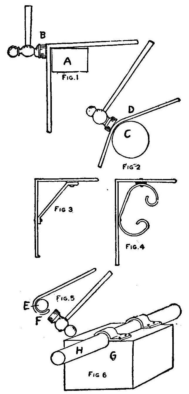
Many an industrious lad has made money manufacturing the common
forms of wood brackets, shelves, boxes, stands, etc., but the day
of the scroll saw and the cigar-box wood bracket and picture
frame has given way to the more advanced and more profitable work
of metal construction. Metal brackets, stands for lamps, gates,
parts of artistic fences for gardens, supporting arms for signs,
etc., are among the articles of modern times that come under the
head of things possible to construct of iron in the back room
or attic shop. The accompanying sketches present some of the
articles possible to manufacture.
First, it is essential that a light room be available, or a
portion of the cellar where there is light, or a workshop may be
built in the yard. Buy a moderate sized anvil, a vise and a few
other tools, including bell hammer, and this is all required for
cold bending. If you go into a forge for hot bending, other
devices will be needed. Figure 1 shows how to make the square
bend, getting the shoulder even. The strip metal is secured at
the hardware store or the iron works. Often the strips can be
secured at low cost from junk dealers. Metal strips about 1/2 in.
wide and 1/8 in. thick are preferable. The letter A indicates a
square section of iron, though an anvil would do, or the base of
a section of railroad iron. The bend is worked on the corner as
at B, cold. If a rounded bend is desired, the same process is
applied on the circular piece of iron or the horn of an anvil.
This is shown in Fig. 2, at C. This piece of iron can be
purchased at any junk store, where various pieces are always
strewn about. A piece about 20 in. long and 4 in. in diameter is
about the right size. The bend in the metal begins at D and is
made according to the requirements. Occasionally where sharp
bends or abrupt corners are needed, the metal is heated previous
to bending.
Although the worker may produce various forms of strip-metal
work, the bracket is, as a rule, the most profitable to handle.
The plain bracket is shown in Fig. 3, and is made by bending the
strip at the proper angle on form A, after which the brace is
adjusted by means of rivets. A rivet hole boring tool will be
needed. A small metal turning or drilling lathe can be purchased
for a few dollars and operated by hand for the boring, or a
common hand drill can be used. Sometimes the bracket is improved
in design by adding a few curves to the end pieces of the brace,
making the effect as shown in Fig. 4. After these brackets are
made they are coated with asphaltum or Japan; or the brackets may
be painted or stained any desired shade.
In some of the work required, it is necessary to shape a complete
loop or circle at the end of the piece. This may be wrought out
as in Fig. 5. The use of a bar of iron or steel is as shown. The
bar is usually about 2 in. in diameter and several feet in
length, so that it will rest firmly on a base of wood or stone.
Then the bending is effected as at F, about the bar E, by
repeated blows with the hammer. After a little practice, it is
possible to describe almost any kind of a circle with the tools.
The bar can be bought at an iron dealers for about 40 cents. From
the junk pile of junk shop one may get a like bar for a few
cents.
A convenient form for shaping strip metal into pieces required
for brackets, fences, gates, arches, and general trimmings is
illustrated at Fig. 6. First there ought to be a base block, G,
of hard wood, say about 2 ft. square. With a round point or
gouging chisel work out the groove to the size of the bar,
forming a seat, by sinking the bar, H, one-half its depth into
the wood as shown. In order to retain the bar securely in
position in the groove, there should be two caps fitted over it
and set-screwed to the wooden base. These caps may be found in
junk dealers’ heaps, having been cast off from 2-in. shaft boxes.
Or if caps are not available, the caps can be constructed from
sheet metal by bending to the form of the bar, allowing side
portions or lips for boring, so that the caps can be set screwed
to the wood. Thus we get a tool which can be used on the bench
for the purpose of effecting series of bends in strips of metal.
Since the introduction of the laws requiring that signs of
certain size and projection be removed from public thoroughfares
in cities, there has been quite a call for short sign brackets,
so termed, of the order exhibited in Fig. 7. These
sign-supporting brackets do not extend more than 3 ft. out from
the building. A boy can take orders for these signs in almost any
city or large town with a little canvassing. The sign supporting
bracket shown is merely a suggestion. Other designs may be
wrought out in endless variety. A hook or eye is needed to
sustain the ring in the sign.
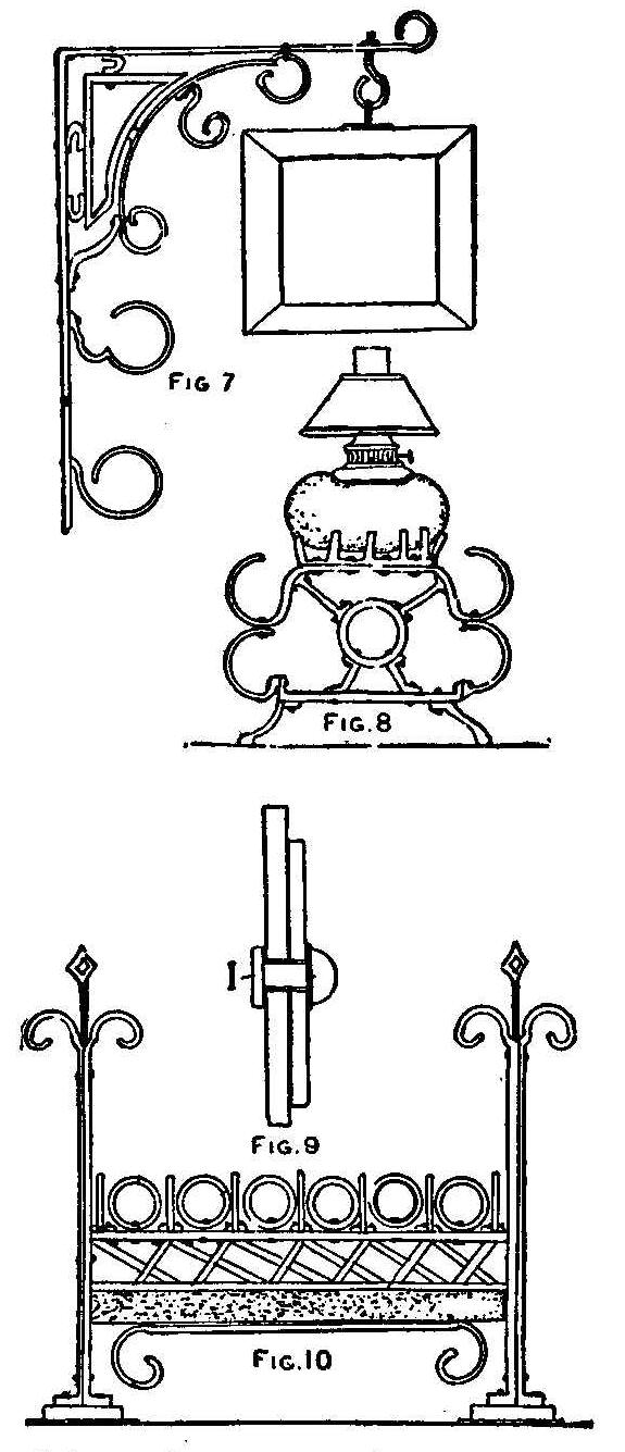
The young man who undertakes to construct any sort of bracket,
supports, frames or the like, will find that he will get many
orders for lamp-supporting contrivances, such as shown at Fig. 8.
It is hardly necessary to go into details for making these
stands, as every part is bent as described in connection with the
bending forms, and the portions are simply riveted at the
different junctures. Both iron and copper rivets are used as at
I, in Fig. 9, a cross sectional view.
The best way is to bore straight through both pieces and insert
the rivet. In some cases the rivet is headed up in the bore and
again washers are used and the heading effected on the washer.
Copper rivets are soft and easily handled, but are costly as
compared with iron rivets.
Good prices are obtained for the guards for open fireplaces made
in many varieties in these days. The return of the open fireplace
in modern houses has created a demand for these guards and in
Fig. 10 we show a design for one of them. The posts are made
sufficiently stiff by uniting two sides with rivets. The ends at
top are looped as shown, while the ends or butts at the base are
opened out to make the feet. Rings are shaped on forms and are
then riveted to the base cross-piece as illustrated. Crosses are
made to describe to central design and the plan is worked out
quite readily with the different shapes.
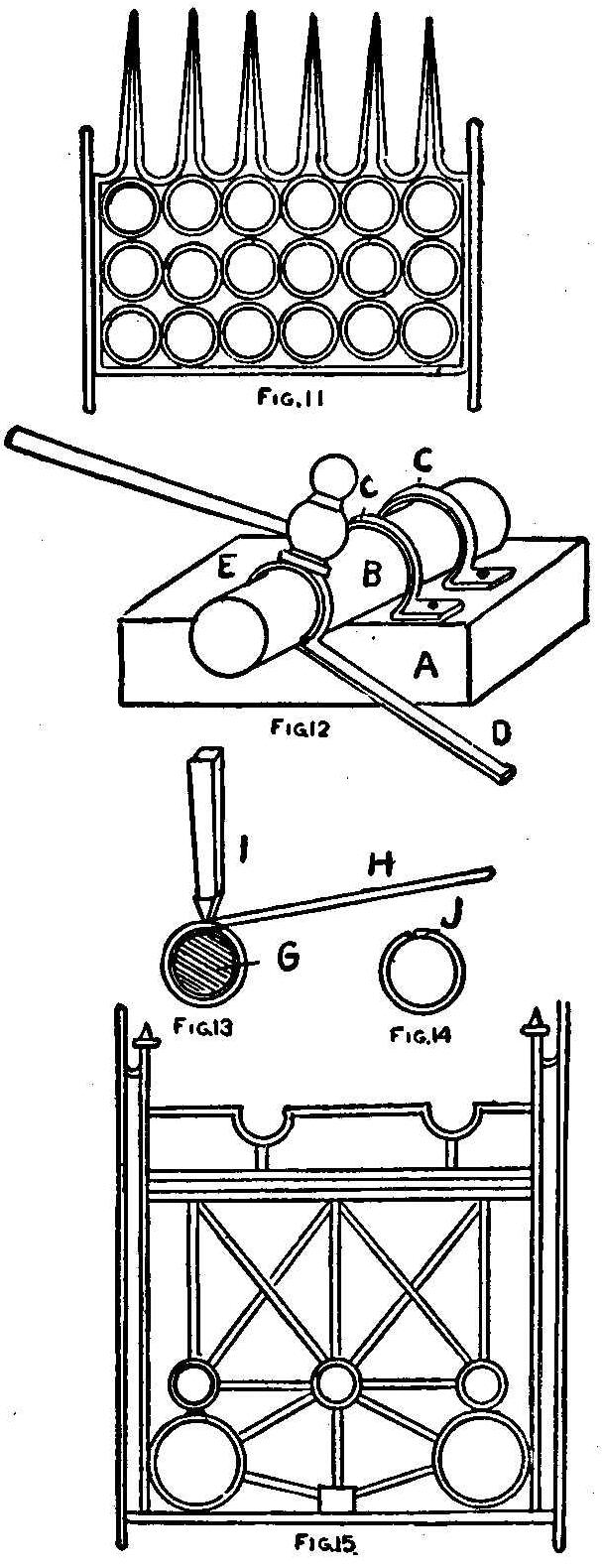
The making of metal fire grate fronts has proven to be a very
interesting and profitable occupation for boys in recent times.
Not long ago it was sufficient for the ingenious youth to turn
out juvenile windmills, toy houses and various little knickknacks
for amusement. The modern lad wants more than this. He desires to
turn some of his product into cash. Therefore we present some of
the patterns of fire grates which boys have made and can make
again from scrap iron, with few tools and devices, and find a
ready market for the same as soon as they are made. Figure 11 is
a sketch of a form of fire grate bar or front that is constructed
with a series of circles of strip metal. The best way is to go to
the hardware store or iron dealer’s and buy a quantity of
1/4-in., 1/2-in., and 3/4-in. iron, about 1/8 to 3/16 in. thick.
In fact 1/16-in. metal would do in many cases where the parts are
worked out small in size. The 1/8-in. metal is very strong. Then
after getting the supply of strip metal in stock, procure the
usual type of metal worker’s hammer, a cheap anvil, a 9-lb. vise,
a cold chisel, a file or two, and a round piece of shaft iron,
about 3 in. diameter and 2 to 3 ft. long. This piece of iron is
represented at B, Fig. 12.
The iron is held in position by means of the straps of metal C,
C, which are bent over the shaft tightly and grip the board base
with set or lag screws as shown. The wooden base should be about
2 in. thick and large enough to make a good support for the iron
shaft. The process of bending the rings in this way is as shown.
The piece of strip iron is grasped at D. Then with the hammer the
iron is gradually worked cold about the mandrel as at E until the
perfect form is acquired. After the form is finished, the strip
at the terminus of the ring is cut off. In order to get a steady
base the wooden part may be bolted to a bench. In Fig. 13 is
shown the method of clipping off the completed ring. The cold
chisel is held upright, and by delivering several blows with the
hammer upon the same, the point is caused to chip through the
metal and release the ring. The shaft or mandrel is marked G. The
cold chisel is indicated at I and the position where the hand
grasps the strip is at H. The final operation in shaping the ring
is by driving the protruding cut, lip down, to the common level
of the opposite point, thus giving us the finished ring with the
lips closed on the mandrel as at J, Fig. 14. These rings can be
turned out in this way very speedily. The next operation involves
the process of uniting the rings in the plan to shape the design.
The design work is often worked out ahead and followed. Some
become so proficient that they can develop a design as they
proceed.
Figure 11 is a design of grate front used for various purposes in
connection with grate fires. The series of rings are united by a
rivet between each at the joining point. With thin metal the
holes can be punched with an iron punch and hammer on an anvil
where there is a hole to receive the point of the punch after the
punch penetrates the metal. For the heavier forms of metal a
drill is necessary. A metal drill and brace can be purchased very
cheaply for this work. After drilling the holes, the parts are
erected and the rivets inserted and headed up as each addition is
made. Thus the series of rings are united and then the side
pieces are similarly riveted. The points at the top are then
worked out and joined on. These points are filed down to the
necessary taper after the union is effected. The finishing work
involves smoothing rough places with a file and painting.
Asphaltum makes a good black finish. Some of the best designs of
grates are bronzed. Some are silvered. The different designs are
finished as desired by customers.
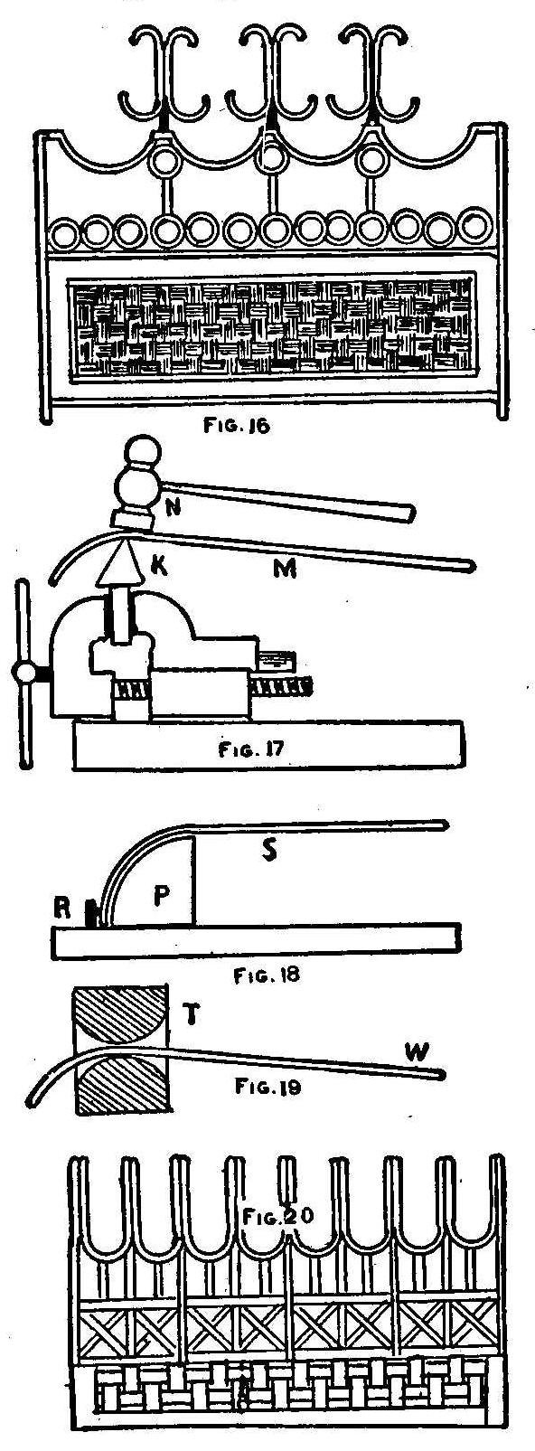
Figure 15 is another design of grate in which the process of
shaping the rings is like that in the first design. There are
some half circles in this pattern and these are framed by shaping
the same about the mandrel with the hammer. In order to get the
shoulders close and the circle complete it is necessary to heat
the metal. A coke fire can be made in a hole in the ground. Then
procure a tin blowpipe and blow the flame against the metal at
the point to be bent. This metal will become red hot very soon,
and can be bent readily against the anvil and the circular form.
Let the metal cool off on the ground after heating. Fig. 16 is
another design which can be wrought out. The middle adjustment is
wire screen work which may be bought at a hardware store and set
into the position shown. Fig. 17 shows a chipping off device
useful in connection with this work. Metal chippers can be bought
at any tool store. The chipper is placed in the jaws of the vise
as at K, and secured there. The strip of metal in process of
cutting is marked M. The hammer head is caused to strike the
metal just over the cutting edge of the chipper. The quick, hard
blow causes the cutting edge to penetrate far enough to sever the
piece. Bending cold with a wooden form is done as in Fig. 18. The
wooden form is marked P and is about 8 in. wide and 7 in. high,
forming a one-sided oval shape. There is a pin R set into the
base board of the oval form and the strip of metal for bending is
grasped at S and the other end is inserted back of the pin R. By
applying pressure, the strip of metal is bent to the form.
Figure 19 shows the hour-glass wood bending form, made by
selecting a piece of hard wood block, about 6 in. square and
boring through with an inch bit. Then the hole is shaped
hour-glass like. The view is a sectional one. The block is placed
in a vise and the strip for bending is inserted as at T.
The strip of metal is grasped at W and can be bent to various
forms by exerting pressure. Fig. 20 is another type of fireplace
front, constructed by uniting the shaped metal pieces. In fact an
almost endless variety of designs can be wrought out after the
start is once made. A good way to figure the price on the grate
is to add up the costs of the parts and charge about 12 cents per
hour for the work.
How to Make a Water Wheel
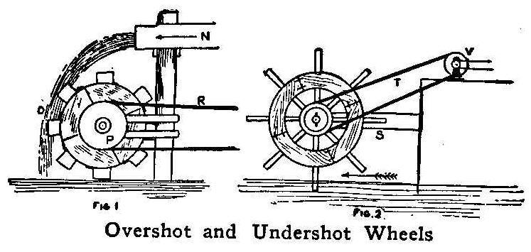
Overshot and Undershot Wheels
Considerable power can be developed with an overshot water wheel
erected as in Fig. 1. This wheel is made with blocks of wood cut
out in sections as indicated by the lines, so as to form the
circle properly. The wheel can be about 24 in. in diameter to
produce results and about 10 in. wide. Get some tin cans and
attach them around the wheel as shown. Bore the wheel center out
and put on the grooved wood wheel, P, and a rope for driving, R.
This rope runs to a wooden frame in the manner illustrated. The
water is carried in a sluice affair, N, to the fall, O, where the
water dippers are struck by the volume and from 2 to 4 hp. will
be produced with this size of wheel if there is sufficient flow
of water. This power can be used for running two or three sewing
machines, fans, fret-saws, and the like. Another form of water
wheel is shown in Fig. 2. This is driven by an underflow of
current. This type of wheel can be made on lines similar to the
other, only that the paddles are of wood and extend outward as
shown. The wheel is supported in a bearing on the piece S. A
belt, T, communicates the power to the wheel V and from here the
power is carried to any desired point.
How To Build An Imitation Street Car Line
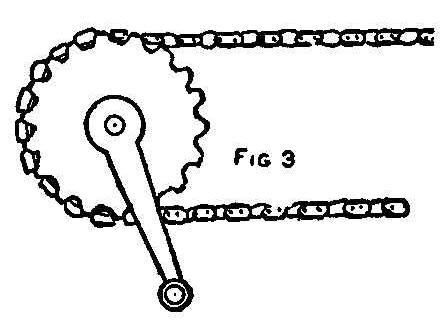
Crank
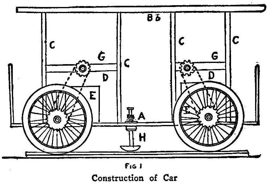
Construction of Car
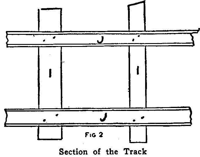
Section of the Track
An imitation street car line may sound like a big undertaking,
but, in fact, it is one of the easiest things a boy can
construct, does not take much time and the expense is not great.
A boy who lives on a farm can find many fine places to run such a
line, and one in town can have a line between the house and the
barn, if they are some distance apart.
Often all the boards and blocks required can be had for helping a
carpenter clear away the rubbish around a new building. Wheels
and parts of old bicycles, which can be used in so many ways, can
be found at a junk shop at very low prices, wheels in good repair
are not expensive. For the car for the street car line try to
find a set of wheels having axles, but if you cannot find such,
make shafts of hard wood, about 3 in. by 2-1/2 in. and by means
of a jackknife turn, or shave down the ends to receive the hub
bearings of the wheels. Fasten the wheel hubs securely over the
ends of the wood with pins or little bolts, or if the wheel
bearing is of such a nature that it revolves on its own journal,
the journal can be fastened to the end of the wood piece. Each of
the wheels should be provided with a sprocket; any chain sprocket
of a bicycle may be used. Fasten these sprockets on the outside
of the wheels as shown in Fig. 1. They can be set on over the
bearing end and secured with a set screw, or the original key can
be employed. It is best in cases like this to use the original
parts. Make the floor of the car of pieces of boards placed on
the axles and nailed, screwed or bolted, as shown at A. To erect
the frame, place uprights, C C C C, in position as shown,
fastening the ends to the base-boards and making the roof line as
at B, then put in the cross-pieces, G G. Seats, E E, are simply
boxes. The drive of the car is effected by using the driving
sprockets, D D, fitted to the crosspieces, G G, with the original
bearings. The parts are thereby secured to the car and the chain
placed on.
Key the cranks for turning to the upper sprocket’s shaft and all
is ready. If there are sprocket gears and cranks on either side,
four boys may propel the car at one time. Considerable speed can
be made on smooth roads, but it is the best amusement to run a
car line on wooden tracks with a brake consisting of a piece of
wooden shaft, passing through a bore in the car floor, and fitted
with a leather covered pad as at H. A spiral spring holds up the
brake until pressure is applied by foot power, when the brake
contacts with the wooden track and checks the car.
The track plan is illustrated in Fig. 2. Get some boards and
place them end for end on other pieces set as ties. The main
boards or tracks, JJ, can be about 6 in. wide, to the edges of
which nail strips about 3/4 in. wide and about the same height.
The ties, I I, can be almost any box boards. Wire nails are the
best to use in putting the tracks together. The sprocket
connection with the chain is shown in Fig. 3. This consists of
the sprocket gear on the propelling shaft, and the crank. The
pedals may be removed and a chisel handle, or any tool handle,
substituted, so as to afford means for turning the crank by hand
power. Great fun can be had with the road, and, furthermore, it
can be made enumerative, as boys and girls can be given rides
for a penny each.
Clean Before Painting
Apply a coat of raw starch water to a dirty wall before painting;
this, when dry, may be brushed or wiped off.
Varnish for Electric Terminals
A good varnish for electric terminals is made of sealing wax
dissolved in gasoline. To prevent brittleness add a little
linseed oil.
Measuring the Height of a Tree
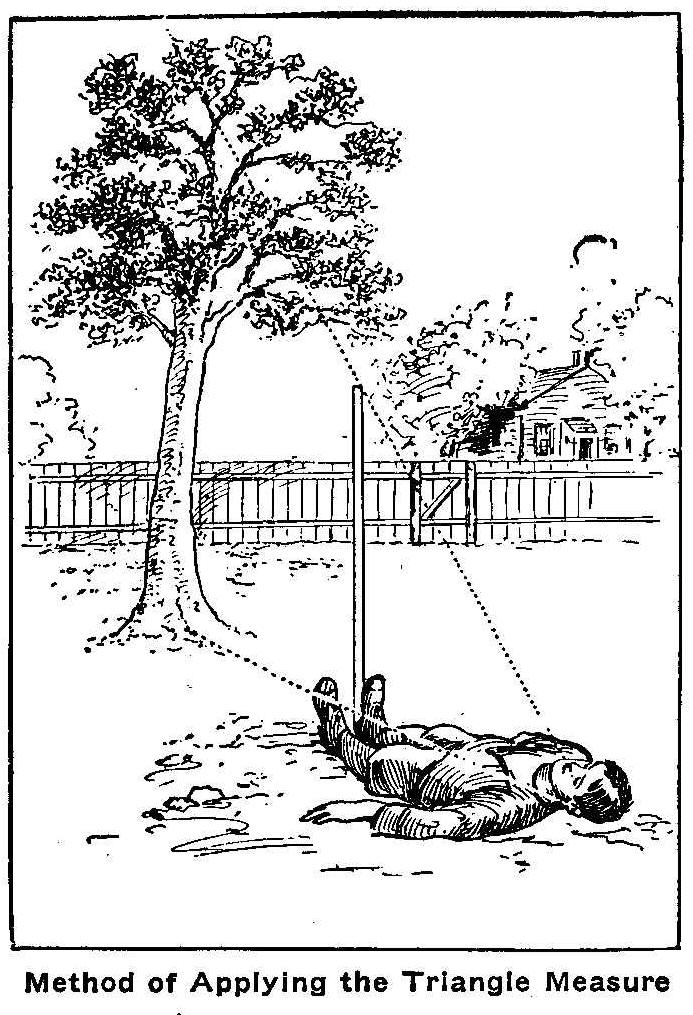
Method of Applying the Triangle Measure
Near the end of the season our boy announced the height of our
tall maple tree to be 33 ft.
“Why, how do you know?” was the general question.
“Measured it.”
“How?”
“Foot rule and yardstick.”
“You didn’t climb that tall tree?” his mother asked anxiously.
“N o’m; I found the length of the shadow and measured that.’
“But the length of the shadow changes.”
“Yes’m; but twice a day the shadows are just as long as the
things themselves. I’ve been trying it all summer. I drove a
stick into the ground, and when its shadow was just as long as
the stick I knew that the shadow of the tree would be just as
long as the tree, and that’s 33 ft.”
The above paragraph appeared in one of the daily papers which
come to our office. The item was headed, “A Clever Boy.” Now we
do not know who this advertised boy was, but we knew quite as
clever a boy, one who could have got the approximate height of
the tree without waiting for the sun to shine at a particular
angle or to shine at all for that matter. The way boy No. 2 went
about the same problem was this: He got a stick and planted it in
the ground and then cut it off just at the level of his eyes.
Then he went out and took a look at the tree and made a rough
estimate of the tree’s height in his mind, and judging the same
distance along the ground from the tree trunk, he planted his
stick in the ground. Then he lay down on his back with his feet
against the standing stick and looked at the top of the tree over
the stick.
If he found the top of stick and tree did not agree he tried a
new position and kept at it until he could just see the tree top
over the end of the upright stick. Then all he had to do was to
measure along the ground to where his eye had been when lying
down and that gave him the height of the tree.
The point about this method is that the boy and stick made a
right-angled triangle with boy for base, stick for perpendicular,
both of the same length, and the “line of sight” the hypotenuse
or long line of the triangle. When he got into the position which
enabled him to just see the tree top over the top of the stick he
again had a right-angled triangle with tree as perpendicular, his
eye’s distance away from the trunk, the base, and the line of
sight the hypotenuse. He could measure the base line along the
ground and knew it must equal the vertical height, and he could
do this without reference to the sun. It was an ingenious
application of the well known properties of a right-angled
triangle.
Railway and Locomotive Engineer.
White Putty to Black
White putty on a black window frame can be made to harmonize by
rubbing the fresh putty with a piece of cotton dipped in
lampblack.
Using Sandpaper
Sandpaper may be kept from slipping under the hand by chalking
the back.
An Interesting Electrical Experiment
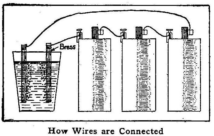
How Wires are Connected
Anyone possessing a battery having an electromotive force of from
4 to 20 volts can perform the following experiment, which is
particularly interesting on account of the variation of results
with apparently the same conditions.
Immerse two pieces of brass in a strong solution of common salt
and water. Connect one piece to the positive wire and the other
to the negative, taking care that the brass pieces do not touch
each other. After the current has passed one or two minutes, the
solution will become colored, and if the process is continued a
colored pigment will be precipitated. The precipitate varies
considerably in color and may be either yellow, blue, orange,
green or brown, depending on the strength of the current, the
strength of the solution, and the composition of the brass.
Novelty Chain Made from a Match
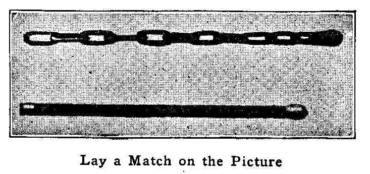
Lay a Match on the Picture
The accompanying engraving shows what is possible to do with a
penknife. A small chain composed of several links was cut from
the wood that forms the match.
Keeping Doors Closed
Glass doors in bookcases may be kept from swinging open by
boring a hole, about 1/4 in. deep, either at the top or bottom in
the edge of the door, 2 in. from the closing edge, and inserting
an ordinary cork, allowing a small portion to project and rub on
the facing.
Restoring Broken Negatives
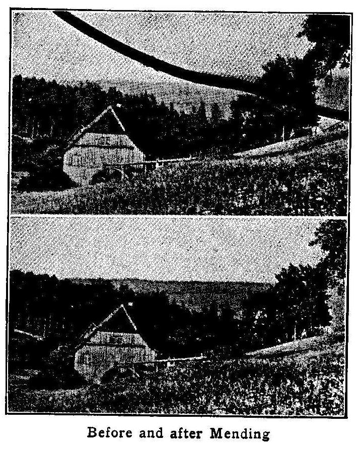
Before and After Mending
Whoever has the misfortune to break a valuable negative need not
despair, for the damage can be repaired most effectively. In case
the negative be broken into many pieces, take a clean glass, the
same size as the broken negative, and put upon this the pieces,
joining them accurately, says Camera Craft. Put another clean
glass on top of this and bind the three together with
passe-partout binding or gummed strips of ordinary paper, as one
would a lantern slide, and cover the glass edges.
Next make a transparency of this—in the camera, of course—and
if it is done right, the positive will only show the cracks as
dark and light lines. The dark lines are removed with the etching
knife and the light ones with the retouching pencil. From this
transparency another negative can be made, or as many negatives
as necessary, by either contact or in the camera, and if the work
on the glass positive was done carefully, no trace of the break
should be seen on the finished negative. If the negative is
broken in two or three larger pieces only, a contact positive may
be made in the printing frame without binding, by using a clean
glass in the latter, upon which the pieces are put together, face
up, and a dry plate exposed in contact with them in the dark
room. The accompanying engravings show a print before and after
repairing a broken negative in this manner.
Coin and Tumbler Trick
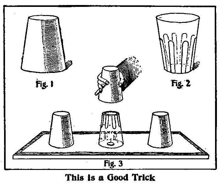
This Is a Good Trick
The accompanying sketch shows how a good trick may be easily
performed by anyone. Lay a piece of heavy paper that is free from
creases on a board or table. Secure three tumblers that are alike
and stick a piece of the same heavy paper over the openings in
two of them, neatly trimming it all around the edges so as to
leave nothing of the paper for anyone to see. Make three covers
of paper as shown in Fig. 1 to put over the tumblers. Place three
coins on the sheet of paper, then the tumblers with covers on top
of the coins, the unprepared tumbler being in the middle. Now
lift the covers off the end tumblers, and you will see that the
paper on the openings covers the coins. Replace the covers, lift
the middle one, and a coin will be seen under the tumbler, as the
opening of this tumbler is not covered. Drop the cover back again
and lift the other tumblers and covers bodily, so that the
spectators can see the coins, remarking at the same time that you
can make them vanish from one to the other. The openings of the
tumblers must never be exposed so that any one can see them, and
a safe way to do this is to keep them level with the table.
Another Way to Renew Dry Batteries
There are many methods of renewing dry batteries, and I have used
several of them, but I found the following the best: Remove the
paper cover and with a 1/4-in. drill make about six holes around
the side of the zinc, about 1/2 in. from the bottom. Then drill
another row of holes about half way up the side and put the
battery to soak in a solution of sal ammoniac for 48 hours. Then
remove and plug the holes up with hard soap, and replace in the
paper box, when it will give nearly as strong a current as when
new.
Simply Made Wire Puzzle
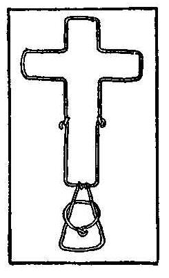
The object of this simply made wire puzzle is to get the ring
off, which is not easy unless you know how. To do so it is
necessary to move the triangle with ring to one of the hinge
joints and fold the puzzle. Then slip the ring off the triangle
over the hinge joint and it will slip all around and off at the
other hinge.
Pronunciation
Diabolo is pronounced Dee-ab-lo.
Repairing Box Cameras
In repairing the inner part of box cameras which have been broken
loose, use a binding of strong black cloth well glued in place.
This will materially strengthen the joints where the wooden
pieces are so thin that it is impossible to use brads in holding
them together.
Do not forget to thoroughly clean all the old glue or cement from
the joints with a rasp or sandpaper before attempting a repair.
A Fishhook Box
Made of Shotgun Shells
A box that may be used to hold fishhooks, sinkers, matches or any
small articles, can be made from two empty shotgun cartridges as
shown in the sketch. The paper is cut from the brass part of one
shell at the place marked A, Fig. 1, and the brass part, Fig. 2,
is used for a cap on the other shell (Fig. 3). Coating the box
with shellac will improve its appearance.
Contributed by Abner B. Shaw, N. Dartmouth, Mass.
A Tin Drinking Cup for the Camp
Handle on a Tin Can
If in need of a drinking cup while camping, a temporary cup can
be made of a tomato or baking-powder can. Punch two holes near
the top of the can; bend a piece of wire and place the ends
through the holes as shown at A in the sketch. Pull the ends to
draw the loop close up on the inside of the tin and then twist
the ends to form a handle as shown at B. When there is enough
wire twisted to form a good handle, pass the ends around the can
at the bottom and twist them together on the opposite side.
Contributed by W. A. Lane, El Paso, Tex.
A Bookmark
A very handy bookmark can be made by attaching a narrow ribbon to
an ordinary paper clip and using it as shown in the sketch. The
clip is slipped over the binding in the back of the book as shown
in the sketch.
Contributed by Chester E. Warner, Kalamazoo, Mich.
Kitchen Knife Sharpener
Sharpener on Table Edge
A good serviceable knife sharpener may be made from a piece of
steel cut as shown with two screw holes drilled for fastening it
to a piece of wood or to a table. The knife is drawn through and
sharpened on either side. Both positions of the knife are shown.
The steel is hardened before fastening it in place.
Contributed by George Madsen, Chicago. Ill.
Devices of Winter Sports
How to Make and Use Them
Tip Up Pole
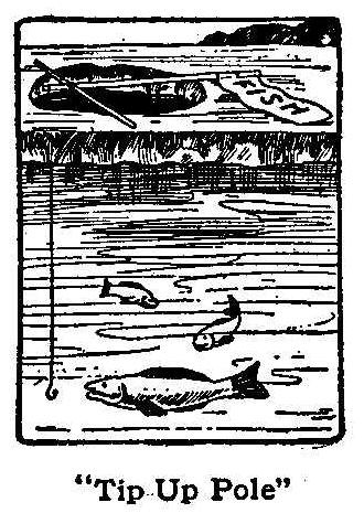
Tip Up Pole
In the north the red-cheeked boy digs a hole in the ice and while
he amuses and invigorates himself at skating, the fish underneath
the icy sheet fasten themselves to the hook he has let down
through a hole. The boy used to sit over the hole in the ice and
wait for the fish to bite, but that became too slow and detracted
too much from his pleasure at skating. So his inventive genius
set itself to work and the “tip-up” and “signal” shown in the
illustration was the result. When the fish is not biting the flag
lies flat on the ice, but as soon as a fish has swallowed the
hook the flag pole stands straight up wafting its bright colored
flag to the breezes and all the boys on the skating pond read the
word “fish.” The fish is drawn up, the hook rebaited and the
youthful fisherman resumes his pleasures on the ice. Often a
score or more of these “tip-ups” are planted about the edges of
the ice pond, each boy bringing his fishing tackle with his
skates and thus finding a double source of amusement. Maybe one
boy will thus have a half dozen different lines in the water at
once, it being easy to watch them all together.
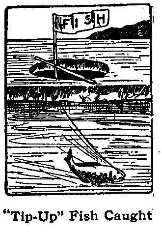
Tip-Up Fish Caught
The device by which the fish is made to give its own signal when
caught is exceedingly simple and any boy can make it. Procure a
light rod about 2 ft. in length and to one end fasten a small
flag, made of any bright colored cloth. Bind the rod at right
angles to another stick which is placed across the hole, so that
a short piece of the flagrod projects over the cross stick. To
this short end fasten the fishing line. Be sure and use strong
string in binding the two rods together, and also take care that
the cross stick is long enough to permit several inches of each
end to rest on the ice. After fastening the line to the short end
of the rod, bait the hook with a live minnow or other suitable
bait and let it down through the hole. When the fish is hooked
the flag will instantly raise and wave about strenuously until
the fish is taken from the water.
Jumping-Jack Fisherman
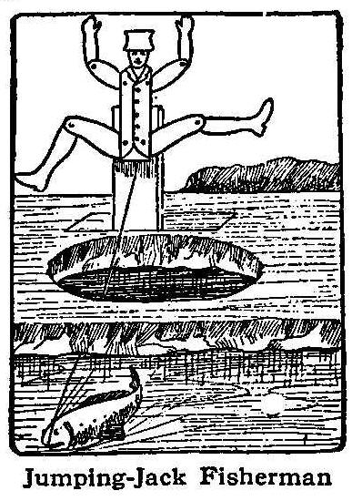
Jumping-Jack Fisherman
If the small boy has a “jumping-jack” left over from Christmas.
he may make this do his fishing for him and serve as well as the
“tip-up,” or he can easily make the jumping-jack himself
independent of Santa Claus. The string which is pulled to make
the joints move is tied securely to the fishing line; the hook is
baited and lowered into the water through a hole in the ice. The
“jumping-jack” waves his legs and arms frantically to notify the
boys when the fish is biting. The “jumping-jack” is also used for
fishing in summer time by placing it on a float which is cast
into the water.
Merry-Go-Round Whirl on Ice
A German device for the amusement of children is a whirl on an
ice merry-go-round. It is made by placing a vertical shaft or
stake, provided with a couple of old cart-wheels, in a hole in
the ice. One wheel acts as a turning base and prevents the shaft
from sinking into the pond, and the other forms a support for the
long sweep attached for propulsion purposes, and should be
fastened to the shaft about 3 ft. above the base wheel. The sleds
are made fast in a string to the long end of the sweep, which
when turned rapidly causes the sleds to slide over the ice in a
circle at a high speed.
If the sweep is long enough to have each
end from the shaft the same length, two strings of sleds may be
attached, which will balance the device and make the turning much
easier.
The Running Sleigh
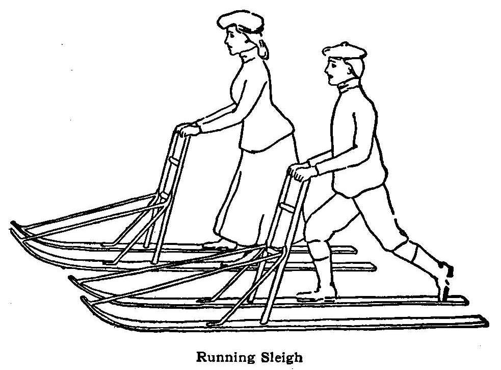
Running Sleigh
Another winter sport, very popular in Sweden, and which has
already reached America, is the “running sleigh,” shown in the
illustration. A light sleigh is equipped with long double runners
and is propelled by foot power. The person using the sleigh
stands with one foot upon a rest attached to one of the braces
connecting the runners and propels the sleigh by pushing backward
with the other foot. To steady the body an upright support is
attached to the runners. The contrivance can be used upon hard
frozen ground, thin ice and snow-covered surfaces, and under
favorable conditions moves with remarkable speed. The “running
sleigh” has a decided advantage over skis, because the two foot
supports are braced so that they cannot come apart. Any boy can
make the sleigh.
The Winged Skater
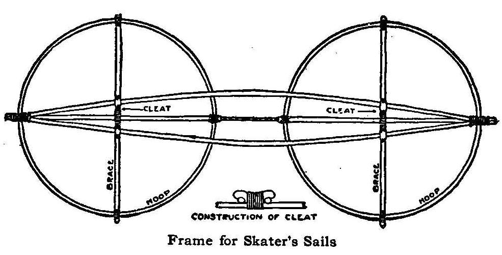
Frame for Skater’s Sails
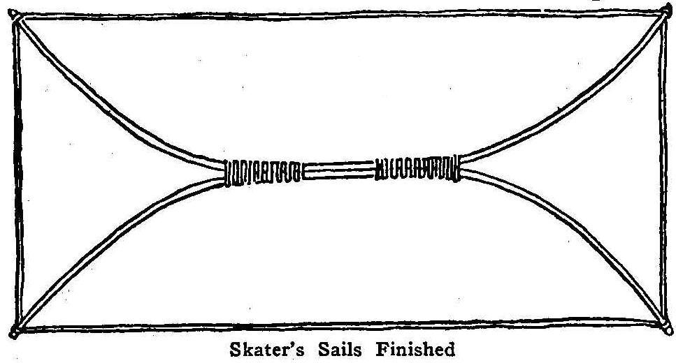
Skater’s Sails Finished
With the actual speed of the wind a skater may be hurled along
the ice if he is aided by sails. He has been known to travel at
the rate of 40 miles an hour, And the sport while affording the
limit of excitement, is not attended with danger. The sails are
easily made, as the illustrations and description will show.
Secure two large thin hoops about 4 ft. in diameter. They may be
obtained from an old hogshead or by bending thin strips. For each
hoop select a piece of strong cane about 3/4 in. in diameter to
constitute the fore and main masts or cross-yards. Extend these
across the center of the hoop and fasten each end firmly to the
hoop’s sides. For the middle of each cross-spar make a cleat and
lash it on firmly. The main spar should also be made of two
pieces of strong cane, each about 9-1/2 ft. long. Bind them
together at each end so that the large end of one is fastened to
the small end of the other.
Next comes the attaching of the sails to the separate masts. The
sails should be made of strong sheeting or thin canvas. Tack the
cloth to the hoop on the inner side after it has been wrapped
around the hoop two or three times.
Now the main spar should be attached by springing it apart and
slipping the cleats of the crossspar between the two pieces. Bind
the inner sides of the hoops tightly together by means of a very
strong double cord, as shown in the figure. Then your sail is
ready for the ice pond. See that your skates are securely
fastened, raise your sail and you will skim along the ice as
lightly as a bird on the wing. With a little practice you will
learn to tack and guide yourself as desired.
If the hoops cannot be easily obtained the sails may be made
equally effective by using the main spar and fore and main masts
as herein described, making the sails square shaped instead of
round and leaving off the hoops. In this case the sails should be
securely bound with strong tape. Attach a corner to each end of
the cross-spar, and a corner to the outer end of the main spar.
The remaining corner of each then appears opposite to each other,
and should be fastened together by strong cord in the same manner
as the hoops. In this case the sails may be left off until after
the frame is entirely put together and then fastened on to the
spars by buttons.
A more simple sail may be made according to the plans illustrated
in the lower drawing. It is made by binding together in the
center the halves of two strong hogshead hoops, or two bent poles
are better. If possible the sail should be about 8 ft. long and 4
ft. wide. Fasten on the sail at the four corners. The rig will
convey two persons and is more easily constructed than any other.
Ice Boating
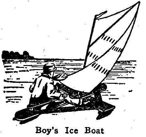
Boy’s Ice Boat
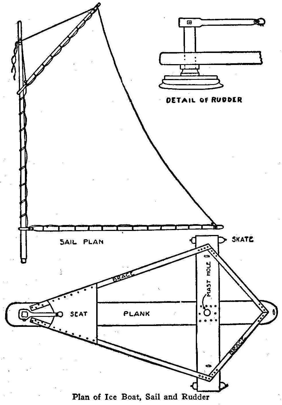
Plan of Ice Boat, Sail and Rudder
But the sport that is greatest of all, the one that used to be
part of the life of every northern boy, and which is being
revived in popularity after years of stagnation, is ice boating.
With the aid of old skates, pieces of board and an old sheet or a
small bit of canvas, any boy possessed of ordinary mechanical
genius may make an ice boat. The frame of the boat should be made
something in the form of a kite. The center-board should be 4 or
5 ft. long, 6 in. wide and 2 in. thick. The cross board may be of
a piece of 1 by 6 in. plank 3 ft. long.
{383}
Fasten these with braces
of small stout strip, as shown in the drawing, and screw the
cross-piece securely to the center-board. Bore a hole in the
center of the intersection for the mast pole. The seat may be
made of a piece of strong cloth or leather. Three skates are
fastened on to either side of the cross-board and one to the
rear end of the center-board, the latter of which is to operate
as a rudder. In attaching the skates first make a couple of
runner blocks, each 6 in. long and 3 in. wide. Bore holes in them
for the straps of the skates to pass through and fasten them
securely. Nail the runner blocks firmly to the crossboard about
1-1/2 in. from each end.
In making the rudder hew down a piece of scantling 1 ft. long
until it assumes the shape of a club with a flat base. Nail a
strip of wood firmly to this base, and to the strip fasten the
skate. Run the top of the club through a hole bored in the stern
of the center-board. Then make the helm by boring a hole in one
end of a strip of soft board about 1 ft. long, and through this
hole pass the club or rubber-pole and fasten it so it may be
shifted when desired. Make the sail out of an old sheet, if it be
strong enough, piece of canvas, or any such substance and attach
it to the mast and sprit as shown in the illustration, and
guide it by a stout string attached to the lower outer corner. As
an ice boat will travel faster than the wind, some care and
considerable skill is necessary. Unless you are accustomed to
managing a sail boat, do not select a place in which to learn
where there are all holes or open water. To stop the boat throw
the head around into the wind, same as you would with a sailboat.
If the wind is strong the occupants of the boat should lie flat
on their stomach.
Coasters and Chair Sleighs
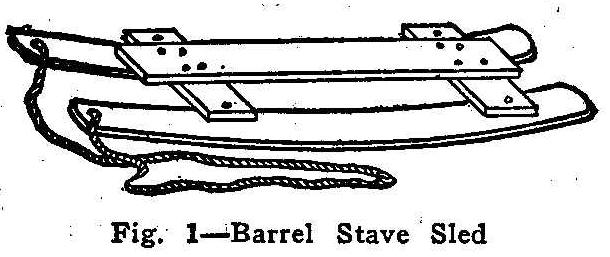
Barrel Stave Sled
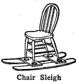
Chair Sleigh
Make your own sled, boys! There is no use in buying them, because
your hand-made sled is probably better than any purchased one and
then you can take so much more pride in it when you know it is of
your own construction. There are so many different designs of
sleds that can be made by hand that the matter can be left almost
entirely to your own ingenuity. You can make one like the bought
sleds and face the runners with pieces of an iron hoop which will
answer every purpose. A good sled for coasting consists simply of
two barrel staves and three pieces of board as shown in the
picture, Fig. 1.
No bought sled will equal it for coasting and it is also just
the thing for carrying loads of snow for building snow houses.
The method of its construction is so simple that no other
description is needed than the picture.
{384}
You can make a
chair-sleigh out of this by fitting a chair on the cross board
instead of the long top board or it will be still stronger if the
top board is allowed to remain, and then you will have a device
that can readily again be transformed into a coasting sled. In
making the chair-sleigh it is necessary, in order to hold the
chair in place, to nail four L-shaped blocks on the cross boards,
one for each leg of the chair. Skating along over the ice and
pushing the chair in front of him the proud possessor of a
chair-sleigh may take his mother, grown sister or lady friend
with him on his outings, and permit her to ride in the chair.
Folding Chair Sleigh
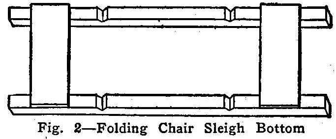
Fig. 2-Folding Chair Sleigh Bottom
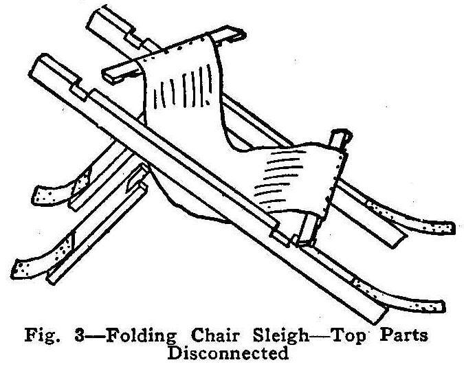
Fig. 3-Folding Chair Sleigh-Top Parts Disconnected
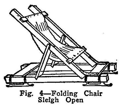
Fig. 4-Folding Chair Sleigh Open
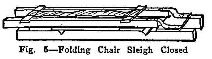
Fig. 6-Folding Chair Sleigh Closed
A folding chair sleigh is even more enjoyable and convenient than
the device just described. If the ice pond is far from home this
may be placed under your arm and carried where you like.
The illustrations, Figs. 2 and 3, show all the parts as they
should look before being joined together. The seat may be made of
a piece of canvas or carpet. The hinges are of leather. Figure 4
shows the folding chair sleigh after it has been put together.
Skates are employed for the runners. The skates may be strapped
on or taken off whenever desired. When the chair is lifted the
supports slip from the notches on the side bars and fall on the
runner bars. The chair is then folded up so that it can be
carried by a small boy. With regular metal hinges and light
timbers a very handsome chair can be constructed that will also
afford an ornamental lawn chair for summer.
The Toboggan Sled
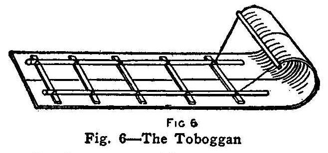
Fig. 6-The Toboggan
When the snow is very deep a toboggan sled is the thing for real
sport. The runners of the ordinary sled break through the crust
of the deep snow, blocking the progress, and spoiling the fun.
The toboggan sled, with its broad, smooth bottom, glides along
over the soft surface with perfect ease.
To make the toboggan sled, secure two boards each 10 ft. long and
1 ft. wide and so thin that they can be easily bent. Place the
boards beside each other and join them together with cross
sticks. Screw the boards to the cross stick from the bottom and
be sure that the heads of the screws are buried deep enough in
the wood to not protrude, so that the bottom will present an
absolutely smooth surface to the snow. Fasten two side bars to
the top of the cross sticks and screw them firmly. In some
instances the timbers are fastened together by strings, a groove
being cut m the bottom of the boards so as to keep the strings
from protruding and being ground to pieces. After the side bars
are securely fastened, bend the ends of the boards over and tie
them to the ends of the front cross bar to hold them in position.
See Fig. 6. The strings for keeping the boards bent must be very
strong. Pieces of stout wire, or a slender steel rod, are even
better. The toboggan slide is the favored device of sport among
the boys in Canada, where nearly every boy knows how to make
them.
The Norwegian Ski
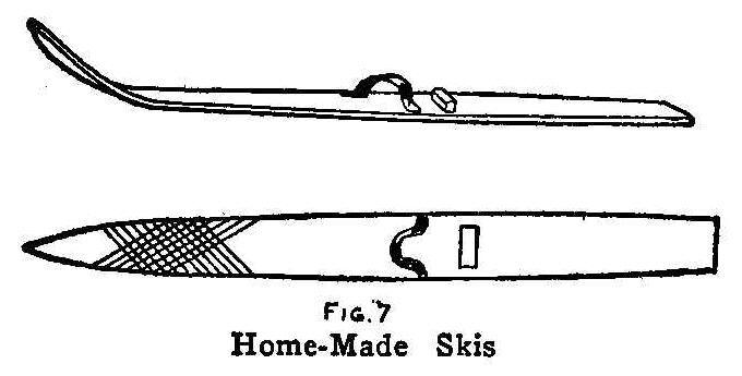
Home-Made Skis
You have often read of the ski, the snowshoe used by the
Norwegians and other people living in the far north. With them
the men and women glide down the snow-covered mountain sides,
leap across ditches, run races and have all kinds of sport. They
are just as amusing to the American boy who has ever learned to
manipulate them, and it is wonderful how much skill can be
attained in their use. Any boy with a little mechanical ingenuity
can make a pair of skis (pronounced skees). They can be made from
two barrel staves. Select staves of straight grained wood.
Sharpen the ends of each and score each end by cutting grooves in
the wood, as shown in the cut, Fig. 7. A pocket knife or small
gouge will suffice for this work. Then smear the end of the
staves with oil and hold them close to a hot fire until they can
be bent so as to tip the toes upward, as shown in the picture,
Fig. 7. Then with a cord bind the staves as they are bent and
permit them to remain thus tied until they retain the curved form
of their own accord. Now screw on top of each ski a little block,
just broad and high enough to fit in front of the heels of your
shoe. Fasten a strap in front of each block through which to slip
your toes, and the skis are made. The inside of the shoe heel
should press firmly against the block and the toe be held tightly
under the strap. This will keep the skis on your feet. Now
procure a stick with which to steer and hunt a snow bank. At
first you will afford more amusement to onlookers than to
yourself, for the skis have a way of trying to run in opposite
directions, crosswise and various ways, but with practice you
will soon become expert in their manipulation.
Home-Made Settee
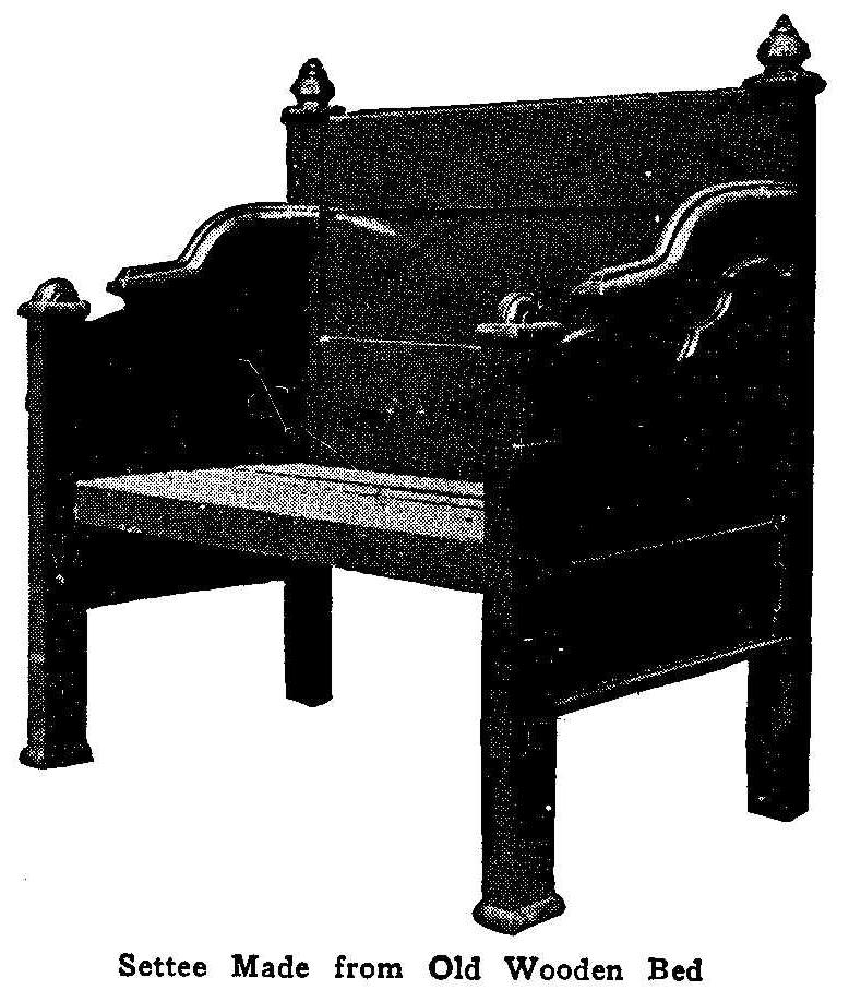
Settee Made from Old Wooden Bed
Many people have old wooden beds stored away which can easily be
made into handy settees like the one shown in the accompanying
photograph. A few nails and one-half dozen 3-in. screws are all
the materials necessary besides the old bed. The tools needed are
a saw, hammer and a screwdriver. The head-board, if too high, can
be cut off and some of the ornaments replaced. The footboard must
be cut in two to make the ends or arms of the settee. The side
rails and a few of the slats are used in making the
seat.
Contributed by Wm. F. Hild, Lake Forest, Ill.
Enameling a Bicycle Frame
Make an enamel by mixing 2 oz. burnt umber with 1 qt. boiled oil,
heating, and then adding 1 oz. asphaltum. Keep the mass hot until
thoroughly mixed, says the Master Painter. Thin with turpentine
while still hot.
Use a camel’s hair brush for applying the enamel
and allow it to set; then place the article in an oven, bake for
six or eight hours at a temperature of 250 deg. F. When cool rub
down with steel wool. Apply a finishing coat and allow it to bake
eight hours at 250 deg. F. Rub down with a soft rag, varnish and
bake again at 200 deg. F. Heat and cool the frame gradually each
time. Black enamel is easiest to apply and bakes hardest, but
requires a temperature of 300 deg. Colors can be baked at from
200 to 250 deg.
How to Make a Sewing Bag
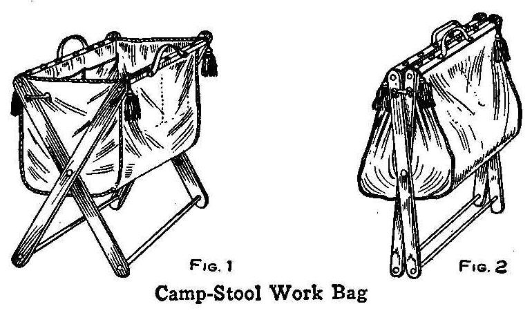
Camp-Stool Work Bag
A very practical and novel sewing bag for odds and ends necessary
for mending, etc., can be made of a folding camp stool. If an old
stool is not at hand, a new one can be purchased for 25 cents.
Remove the top or seat, which is usually made of a piece of
carpet, then make a bag as shown in Fig. 1 and stitch a heavy
cord around the top to make it strong. Make pockets on the inside
as shown and nail the bag to the two crosspieces on which the
ends of the carpet were tacked. Large, brass furniture nails
should be used. Attach a small hook and eye on each end and
fasten two leather handles to the crosspieces.
Such a bag requires little room when folded and can be stored in
a closet when not in use.
Contributed by Joseph Ledwinka, Philadelphia, Pa.
Home-Made Roller Skates
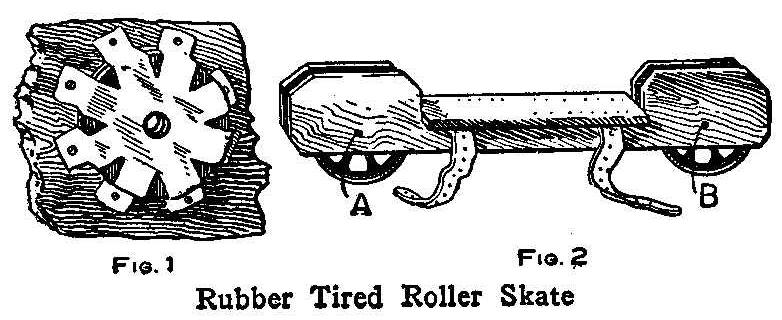
Rubber Tired Roller Skate
The rubber-tired wheels of an old carpet sweeper can be used to
advantage in making a pair of roller skates. In Fig. 1 is shown
how an iron washer or two may be fastened to the wood with a
piece of sheet metal to support the short axles of the wheels.
The wheels are oiled through the holes A and B, Fig. 2. These
holes should be smaller than the axles. The two side pieces are
fastened together with a board nailed on the top edges, as shown.
This board also furnishes the flat top for the shoe sole. Two
straps are attached for fastening the skate to the shoe.
Contributed by Thos. De Loof, Grand Rapids, Mich.
Adjuster for Flexible Electric Wires
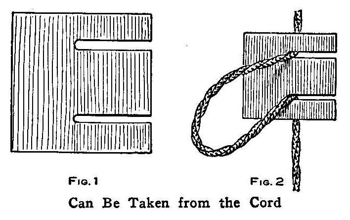
Can Be Taken from the Cord
The accompanying illustration shows an adjuster for changing the
drop of an electric light. The main feature of this adjuster is
that it can be removed from the cord at any time. The adjuster is
made from a piece of wood, 3/8 in. thick, 2 in. wide and 3 in.
long. A 1/4 in. hole is bored in the center near each end of the
wood and a slot cut from the holes to the outside edge, as shown
in Fig. 1. It is attached to the flexible cord as shown in Fig. 2.
Contributed by J.J. Voelcker; Decatur, Ill.
Making Photographs on Watch Dials
Beat to a foam the white of an egg, with the addition of a little
ammonia. Add 9 oz. and 3 dr. of water and beat again. After the
egg has settled, filter and let the liquid run over the dial,
which has been previously cleaned with ammonia. When the surplus
has run off, coat with the mixture and allow to dry.
A sensitive collodion is now produced as follows: Dissolve 9 gr.
of chloride of zinc in 5 dr. of alcohol; add 7-1/2 gr. of
collodion cotton and 6-1/2 dr. of ether. Shake the whole
forcibly.
Dissolve 23 gr. of nitrate of silver in hot water, add 1-1/2 dr.
of alcohol and keep the whole solution by heating. The silver
solution is now added in small quantities at a time to the
collodion, which must be well settled. This, of course, is done
in the dark room. After 24 hours the emulsion is filtered by
passing it through cotton moistened with alcohol. This durable
collodion emulsion is now flowed thinly upon the prepared watch
dial, which, after the collodion has coagulated, is moved up and
down in distilled water until the fatty stripes disappear. The
water is then changed once, and after a short immersion, the dial
is left to dry on a piece of blotting paper. It is now ready for
exposure. Expose under magnesium light and develop with a citrate
oxalic developer, or in the following hydroquinone developer:
| Hydroquinone | 1 dr. |
| Bromide of potassium | 6 dr. |
| Sulphite of soda | 1-1/2 oz. |
| Carbonate of soda | 2-2/3 dr. |
| Water | 14 oz. |
After fixing and drying, coat with a transparent positive
varnish.
Home-Made Overhead Trolley Coaster
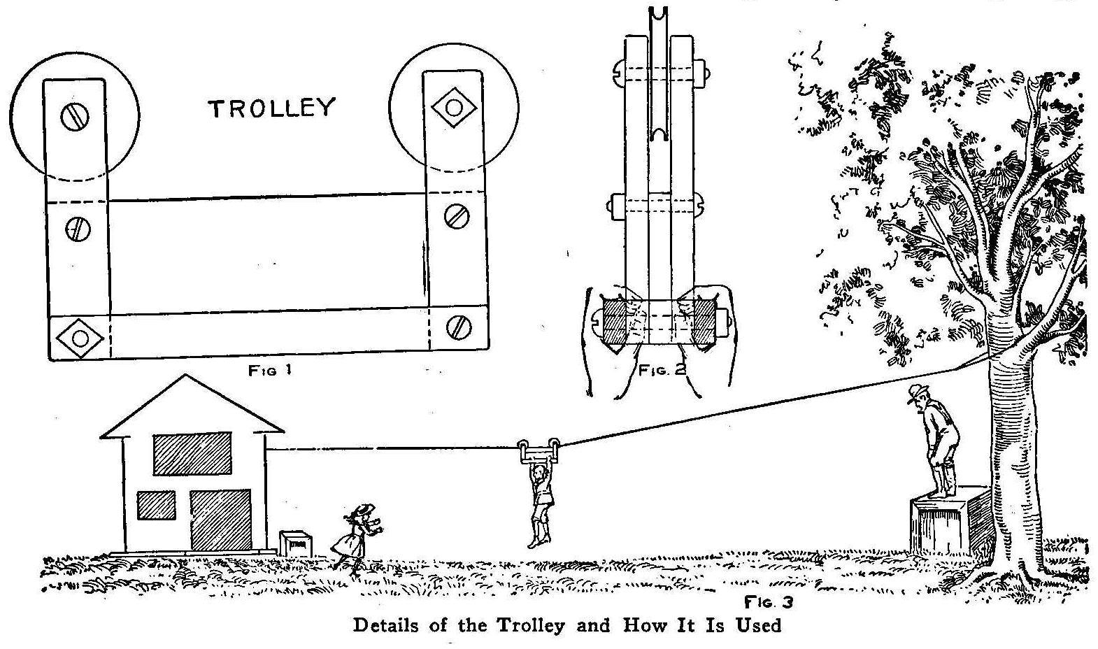
Details of the Trolley and How It Is Used
The accompanying sketch shows a playground trolley line which
furnished a great deal of amusement to many children at a minimum
cost. The wire, which is 3/16 in. in diameter, was stretched
between a tree and a barn across a vacant quarter block. The
strength of the wire was first tested by a heavy man. When not in
use the wire is unhooked from the tree and hauled into the barn
and coiled loosely in the hay loft. The wire was made taut for
use by a rope which was fastened to the beams in the barn. The
trolley was made, as shown in Figs. 1 and 2, of strips of wood
bolted with stove bolts on two grooved pulleys. The middle wide
board was made of hardwood. The wheels were taken from light
pulley blocks and stove bolts were purchased from a local
hardware store to accurately fit the hubs. As it was necessary to
keep the bearings greased, we used vaseline. This coaster made
great sport for the youngsters and at no time were they in danger
of a serious fall as the line was hung low and the slant of the
wire was moderate.
Contributed by H. J. Holden, Palm Springs, Calif.
How to Make an Electric Furnace Regulator
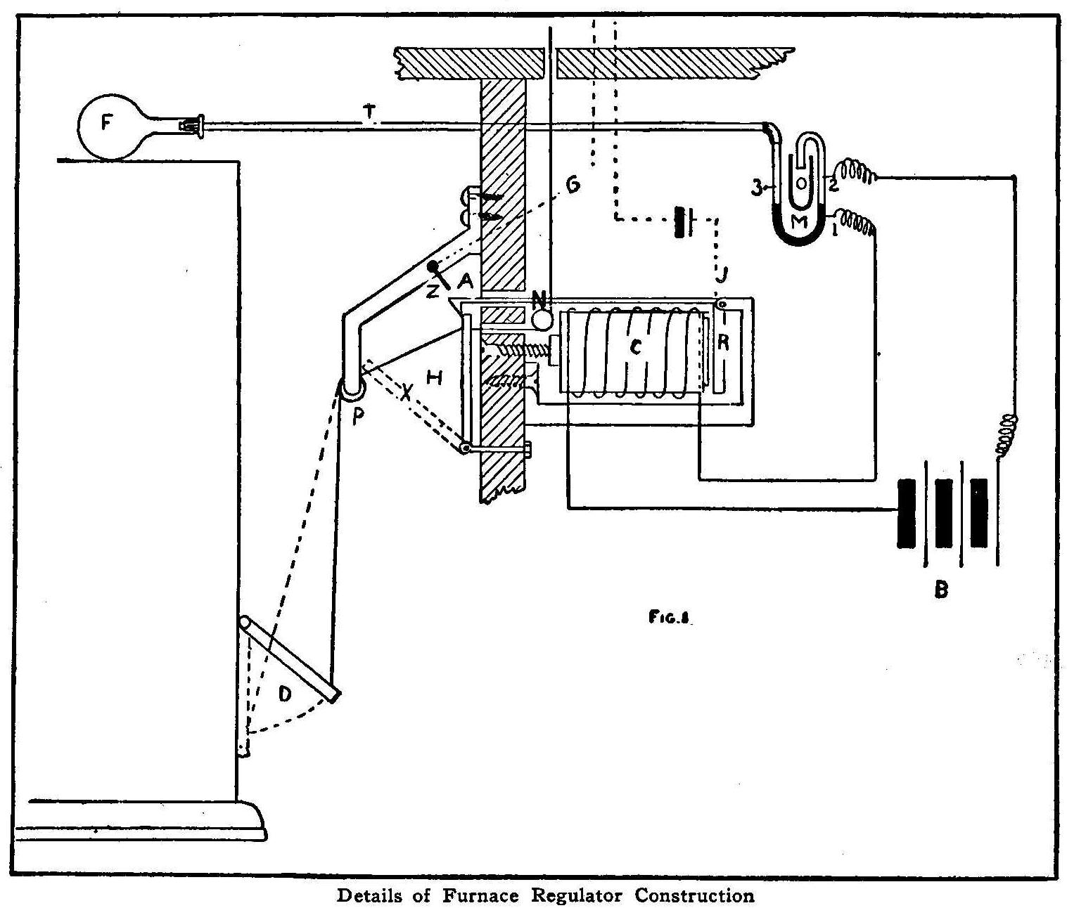
Details of Furnace Regulator Construction
We have a furnace in our house and a part of my work each evening
last winter was to go down in the basement at 9 o’clock, fill the
furnace with coal for the night and stay there until it was
burning in good shape, then to close the draft door. As this
performance requires from twenty to thirty minutes I concluded to
make a self-acting device which would close the draft and leave
the furnace safe, without any further attention on my part, after
putting in the coal and opening it up to burn. As some other boys
may like to build the same regulator I will tell just how to make
one and how it operates.
Referring to Fig. 1, you will see a straight cord is attached to
the draft door of the furnace, D, and is run over the pulley P
and finally is attached to a small piece of iron, H. This piece
of iron is hinged to I. To the other side of H another cord G is
fastened, which passes over the pulley N and terminates in any
convenient place in the rooms above. This piece of iron H is held
in place by the release A. Now C is a coil of wire from a door
bell. R is an armature which works A on pivot J. M is a U-tube,
filled with mercury, one end being
connected to a half liter glass flask F by the tube T, and the
other end terminates in an overflow tube O. B is a battery of
three bichromate cells which are connected up with the C and the
platinum points 1—2, which are fused into the U-tube.
On fixing the furnace the iron piece H takes position X, this
being the normal position when draft door D is closed. On
arriving upstairs I pull the cord G, which causes the piece H to
become fixed in the vertical position by means of A. This opens
the draft door at the same time. Now when the furnace heats up
sufficiently it causes the air to expand in F, which causes the
mercury in M to rise a little above
the point 2. This immediately causes a current to flow through C
which in turn draws R towards it, raises A and causes H to drop
to position X. This shuts the furnace door. Now the furnace, of
course, cools down, thus causing the air in F to contract and
consequently opening the circuit through C. If at any time the
furnace should overheat, the raising of A, on which is grounded a
wire from a signal bell upstairs, will make a circuit through the
bell by means of the point Z and wire leading therefrom. This
bell also serves to tell me whether H has dropped or not. This
same device of regulating the draft D can be used to regulate the
damper, found on the coal doors of most furnaces, by simply
fusing a platinum point on the other side of M and changing the
cord which is attached to D. A two-contact switch could also be
inserted to throw connections from 2 to 3. It would work in this
manner: The damper door, of course, which keeps a low fire, would
be up in a position similar to D; on the furnace cooling too
much, connection, due to contracting of air in F, would be made
through 3 and C, causing H to drop, thus closing door. This
simple device worked very well all last winter and gave me no
trouble whatever.
If you cannot readily procure a U-tube, you can make one, as I
did, and the work is interesting.
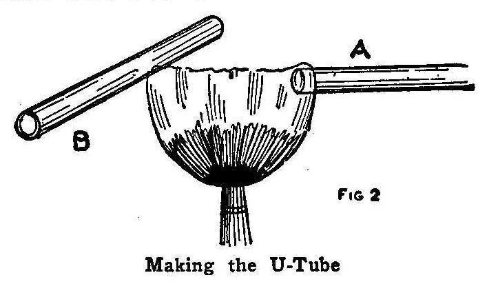
Making the U-Tube
The U-tube is constructed in the following manner. A glass tube
is closed at one end. This is done by holding the tube in one
corner of a gas flame, somewhat near the dark area (A, Fig. 2),
and constantly turning the tube, when it will be found that the
glass has melted together. Now, after it is cool, about 3 or 4
in. from the sealed end, the tube is held steadily so that the
flame will heat one small portion ( B, Fig. 2 ). After this small
portion is heated blow into the tube, not very hard, but just
enough to cause tube to bulge out. Allow to cool. Then reheat the
small bulged portion, blow quite hard, so that the glass will be
blown out at this point, forming a small hole. Now insert about
1/2 in. of platinum wire and reheat, holding platinum wire by
means of a small pliers so that it will be partly in the tube and
partly without. The platinum will stick to the glass, and if
glass is sufficiently heated one will be able to pull it, by
means of pliers, from one side of the hole to the other, thus
sealing the wire into the tube. Another wire is sealed in the
same way about 1 in. from the first. Now, to bend the tube, one
must hold it, with both hands, in the flame and turn constantly
until soft. Quickly withdraw from flame and bend, just as you
would a piece of copper wire. Allow to cool slowly.
The several tubes are connected with a short piece of rubber
tubing.
The total cost of materials for constructing the apparatus
complete will not amount to more than one dollar.
Contributed by M. G. Kopf, Lewis Institute, Chicago.
Weatherproofing for Tents
Dissolve 4 oz. sulphate of zinc in 10 gal. water; add 1/2 lb.
sal-soda; stir well until dissolved, and add 1/2 oz. tartaric
acid. Put the tent cover in this solution and let lie 24 hrs.
Take out (do not wring it) and hang up to dry.
Grinnell’s Hand Book on Painting.
Sawing Sheet Metal
Sheet metal placed between two boards in the jaws of a vise and
clamped tightly, can be sawed easily with a hacksaw.
A Monoplane Weather Vane
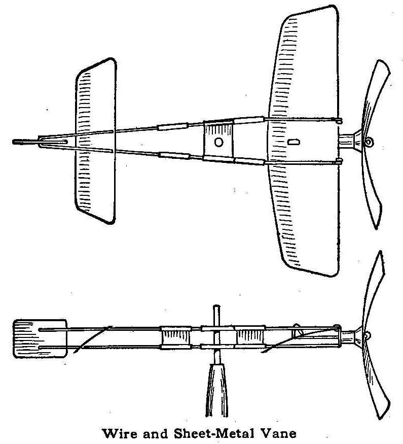
Wire and Sheet-Metal Vane
The toy windmill or weather vane shown in the sketch is made to
represent a Blériot monoplane. The propeller is turned by the
wind. The frame is made of heavy wire and connected with straps
of tin. The construction is plainly shown in the illustration.
The windmill vane can be made in any size to suit the builder.
Contributed by W. C. Bliss, St. Louis, Missouri.
How to Make a Minnow Trap
Glass minnow traps that will give as good service as those
purchased at the tackle store can be made without difficulty. If
a trap should be banged carelessly against the side of the boat
or some other obstruction and smashed, instead of spending
several dollars to replace it, a half hour’s time will turn out a
new one just as good, says a correspondent of Outing.
A trap of this kind can be made from an ordinary fruit jar such
as used in putting up preserves, either of one or two-quart
capacity. A one-quart jar gives good results, but if the bait to
be caught is of fairly large size, the two quart size may be
used. As the jars have the same style top they can be used
interchangeably with one mouthpiece.
The mouthpiece is made of a round neck bottle of which the glass
is colorless and rather thin. If the neck of the bottle is cut at
the right point, it makes a glass funnel that will just fit into
the fruit jar. The funnel forms the mouth of the trap. Put the
neck of the bottle into the fruit jar and mark the glass with a
file where the bottle and jar meet. Make as deep a cut as
possible with a file around the bottle on the mark and place two
turns of a yarn string saturated in kerosene around just below
the cut when the bottle is standing in an upright position. Set
fire to the string and turn the bottle from side to side to
distribute the heat evenly, then when the string has burned out,
plunge the bottle in cold water and it will separate on the
cut.
Bind some copper wire around the neck of the jar so that three
ends will project 1/2 in. or more. These are bent down over the
funnel when put into the jar, forming clamps to hold it in place.
The copper wire can be bent many times in emptying or baiting the
trap without breaking.
Two copper wire bands are tied tightly around the jar about 3 in.
apart. They should be twisted tight with a pair of pliers and the
ends joined, forming a ring for attaching a cord.
For catching “kellies” or “killies,” bait the trap with crushed
clams or salt-water mussels and for fresh water shiners use
mincemeat or bread crumbs and do not spill any bait outside of
the trap. Leave the trap down ten to fifteen minutes and when
resetting it after emptying, put back one or two of the victims,
as the others enter more readily if they see some of their
companions ahead of them.
A Remedy for Leaking Fountain Pens
Fountain-pen leaks may often be prevented by unscrewing the joint
and lightly smearing the screw with vaseline. This also makes it
easy to unscrew the joint for filling.
Kites of Many Kinds and How to Make Them
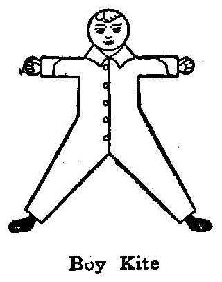
Boy Kite
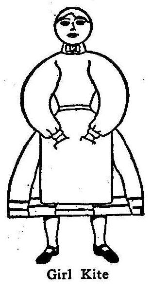
Girl Kite
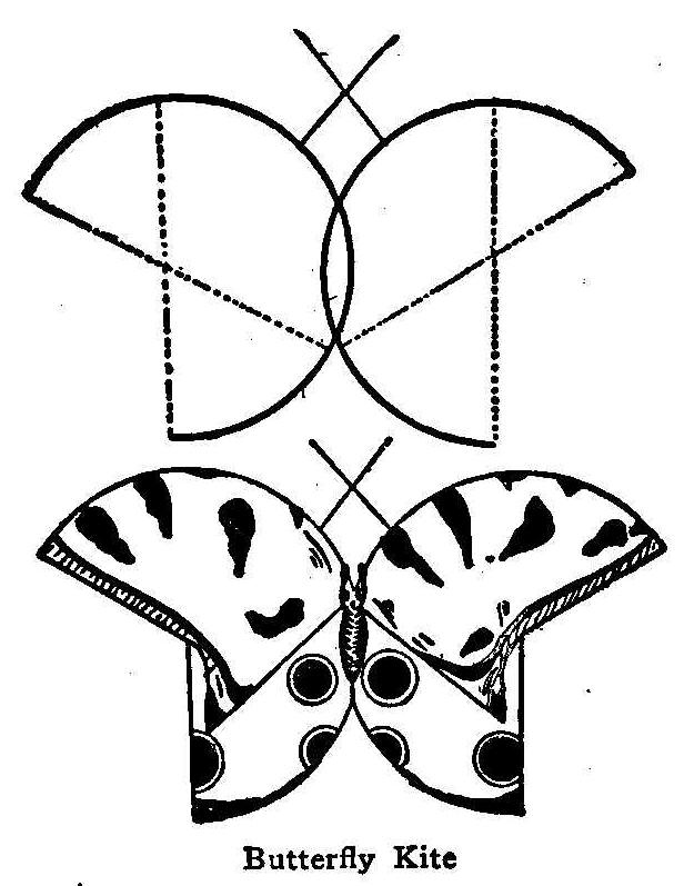
Butterfly Kite
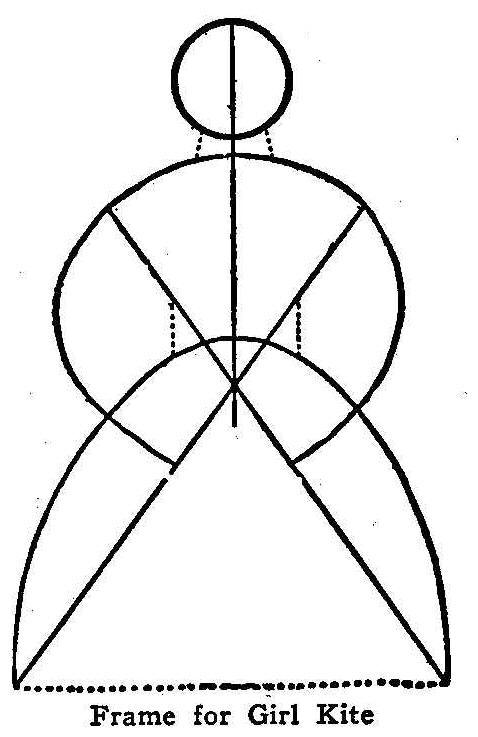
Frame for Girl Kite
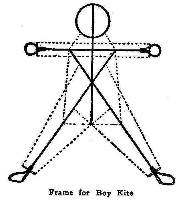
Frame for Boy Kite
One of the prettiest of all is the butterfly kite. To make this
get two thin kite sticks of equal length. Bend each in an are,
tying one end of a strong string to one end of each stick and the
other end of the string to a point about 3 in. from the other end
of the stick. This leaves one end of each stick free, hooking
over the hemisphere described by the thread and the stick. Now
tie another thread to each of these free ends and tie the other
end of the thread to a point near the other end of the stick,
corresponding with the distance from the end at which the first
strings were tied on the opposite side. This done, you should
have two arched frames, each an exact counterpart of the other in
size, curvature and weight. Now fasten the two frames together so
that the arcs will overlap each other as shown in the sketch.
Bind the intersecting points securely with thread. To make the
butterfly’s head, secure two heavy broom straws or two short
wires, and attach them to the top part of the wing frames near
where the sticks intersect, so that the straws or wires will
cross. These form the antennae, or the “smellers.” Then select
the color of paper you want, yellow, brown, blue, white or any
other color; lay it on a flat surface and place the frame on top
of it, holding the frame down securely with a weight. Then with a
pair of scissors cut the paper around the frame, leaving about a
1/2-in. margin for pasting. Cut slits in the paper about 2 in.
apart around the curves and at all angles to keep the paper from
wrinkling when it is pasted. Distribute the paste with a small
brush and make the overlaps a little more than 1/4 in. wide and
press them together with a soft cloth. When the kite is dry
decorate it with paint or strips of colored paper in any design
you may fancy. The best effects are produced by pasting pieces of
colored paper on top of the other paper. Black paper decorations
show up to fine advantage when the kite is in flight. Attach the
“belly-band” to the curved sticks by punching a hole in the paper
in the same manner as it is attached to the common hexagonal or
coffin-shaped kite. With a tail, your kite is ready to fly.
Another interesting design is the boy kite. With light colored
coat and vest and gay striped trousers, the kite standing high in
the air always attracts attention and affords splendid sport for
the American youth in springtime.
In making a boy kite it should be remembered that the larger the
boy is the better he will fly. To construct the frame, two
straight sticks, say 3-1/2 ft. long, should serve for the legs
and body; another straight stick forms the spine and should be
about 2 ft. 4 in. long. For the arms, get a fourth straight stick
about 3 ft. 3 in. long. Make the frame for the head by bending a
light tough stick in a circle about 7 in. in diameter. Bind it
tightly with a strong thread and through its center run the
spine. Then tack on the arm stick 3 in. under the circle so that
the spinal column crosses the arm stick exactly in the center.
Wrap tightly with strong thread and tack on the two sticks that
are to serve for the legs and body. The leg sticks should be
fastened to the arm stick about 6 in. on either side of the
spinal column, and crossed so that the other ends are 3 ft.
apart. Tack them and the arm stick together at the point where
they intersect. Small hoops and cross stick of the same material
as the head frame should be fastened to both extremities of the
arm stick and the lower ends of the leg stick for the hands and
feet. See that both hand frames are exactly alike and exercise
equal caution regarding the foot frames; also see that the arm
stick is at exact right angles with the spine stick and that the
kite joints are all firmly tied and the kite evenly balanced;
otherwise it may be lopsided. Fasten on the strings of the frame,
beginning at the neck at equal distances from the spine, as
indicated by the dotted lines in the diagram. Extend a string
slantingly from the arms tick to the head on both sides of the
spinal column, and run all the other strings as shown in the cut,
being careful that both sides of the frame correspond in
measurements.
To cover the kite, select different colors of paper to suit your
taste, and after pasting them together, lay the paper on the
floor and placing the frame on it, cut out the pattern. Leave an
edge of 1/2 in. all around and make a slit in this edge every 6
in. and at each angle; make the slits 2 in. apart around the
head. After the kite is pasted and dry, paint the buttons, hair,
eyes, hands, feet, etc., as you desire. Arrange the “belly band”
and tail band and attach the kite string in the same manner as in
the ordinary coffin-shaped kite.
The “lady kite” is made on the same principle as the boy kite.
The frame may be made exactly as the boy kite and then “dressed”
with tissue paper to represent a girl, or it may be made on the
special frame, page 81. Remember the dotted lines represent the
strings or thread, and the other lines indicate the kite sticks.
Be careful with your measurements so that each side of the kite
corresponds exactly and is well balanced. Also see that every
point where the sticks intersect is firmly tacked and bound.
To cover the kite, first paste together pieces of tissue paper of
different color to suit your taste. The paste should be made of
flour and water and boiled. Make the seams or overlaps not quite
3/8 in. wide. Lay the paper on the floor, using weights to hold
it down, and place the frame of the kite upon it. Then cut out
the paper around the frame, leaving an edge of 1/2 in. Don’t
forget to make a slit in the edge every 6 or 7 in. and at each
angle. Around the head the slits are cut 2 in. apart, as in the
case of the boy kite. After the kite is dry, paint the paper as
your fancy dictates.
To make the breast band, punch holes through the paper, one upon
each side of the leg sticks, just above the bottom, and one upon
each side of the arm sticks at the shoulder. Run one end of the
string through the hole at the bottom of the left limb and tie it
to the leg stick; tie the other end at the right shoulder. Fasten
one end of another string of the same length at the bottom of the
right leg; pass the string up across the first band and tie the
other end at the left shoulder. Attach the kite string to the
breast band at the point where the two strings intersect. Tie the
knot so that you can slide the kite string up or down until it is
properly adjusted. The tail band is made by tying a string to the
leg sticks at the bottom of the breast band. Let the string hang
slack below the skirt and attach the tail to the center. The same
general rules apply in attaching the string and tail to the boy
kite.
You can make the lady look as if dancing and kicking in the
clouds by making the feet of stiff pasteboard and allowing them
to hang loose from the line which forms the bottom of the skirt.
The feet will move and sway with each motion of the kite.
How to Make Rubber Stamps
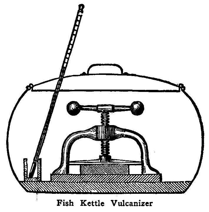
Fish Kettle Vulcanizer
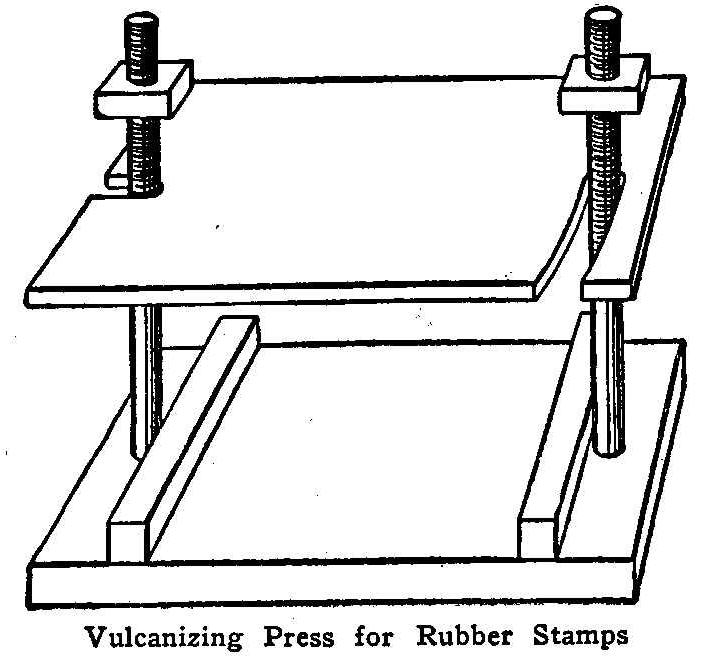
Vulcanizing Press for Rubber Stamps
India rubber, especially prepared for stamp-making, should be
procured from a dealer or manufacturer, if good results are to be
obtained. As an experiment, it is possible for an amateur to
prepare the rubber, but, in such cases, it is always attended
with uncertain results. The mixed uncured rubber comes in white
sheets, strong, firm and about 1/8 in. thick, and for its
manipulation a press is indispensable, but can be home-made.
For the base of the press use a piece of iron, having two holes
drilled in it at the middle of opposite sides, through which pass
bolts, letting the thread ends extend upward and counter-sinking
places for the bolt heads to keep the under side of the base
level. Solder the bolts in place at the base. The upper part of
the press, or the platen, is also of iron, cut so it can be swung
off the bolts, rather than by removing the nuts and lifting it
off. String a half dozen nuts, larger than those which screw on,
on each bolt, so that when the upper nut on each is screwed to
the extent of the thread the pressure will be communicated
through the nuts wedged in between the platen and the upper nut.
The bolt holes in the platen should be directly over those in the
base. Distance pieces of an exact thickness should be provided
for use on the base; these serve to keep the pressure even.
In preparing the mould, if type is to be copied, use rather large
type with wide spaces and set up with high quads and spaces, or
the type faces may be filled up by rubbing with either wax, or
soap, lightly brushing off any that remains loose. The type so
set should be locked into a frame. This may be made of two pieces
of wood bolted together at both ends, or of printer’s furniture.
Place it on a flat surface (marble is good, but any perfectly
smooth surface will do) and place distance pieces 1/8 in. higher
than its upper surface on either side of it. Apply olive oil to
the type faces and wipe off any excess. To form the matrix or
reverse of the model, take a piece of iron larger than the
inscription to be copied, and spread upon it to a depth of 1/4
in, a putty made by mixing plaster of paris and water to the
right consistency.
{394}
By means of a table knife spread the plaster
smoothly and then invert the plate upon the model and press down
until the distance pieces are struck. Let it set 10 minutes and
then remove. If care has been taken the matrix will be perfect.
After it has thoroughly dried, preferably in an oven, saturate it
with an alcoholic solution of shellac to strengthen it.
Cut a piece of smooth rubber, large enough to cover the matrix,
from the sheet, throw this into a box of talc, or powdered
soapstone, so that it receives a coating on both sides; dust a
little of the powder over the matrix, also. Place the press on a
support over a gas burner; or a kerosene lamp, and apply the
heat. Place the matrix on the base of the press, dust off the
piece of india rubber and place in the press upon the matrix and
screw down the platen. Heat the press to 284 deg. F. and keep
screwing down the platen so that the rubber, now soft and
putty-like, is forced into every recess of the matrix. A
thermometer is not necessary; some rubber always protrudes and
the stage of the process can be told from that. At first it is
quite elastic, then as the heat increases it becomes soft, then
the curing begins and it again becomes elastic, so that, if a
point of a knife blade is pressed against it, it resumes its
shape when the point is removed. When this takes place it is then
thoroughly vulcanized and the sheet can be removed from the
matrix. Ten minutes, under favorable conditions, is sufficient
time for moulding the rubber. By means of common glue, or bicycle
tire cement, fasten the rubber stamp to a wooden handle.
It is possible to dispense with the press in making stamps, where
the work is not done in quantities, and use a hot flat-iron. The
matrix is placed on a stove at low heat, the rubber laid on and
the hot iron applied. But a few moments are required to mould
it.
An old letter press if it be inclosed in a tin oven makes a good
press, or all the necessary materials and apparatus can be
purchased from a dealer. Any type such as all printers use will
answer.
To Light a Gaslight Without Matches
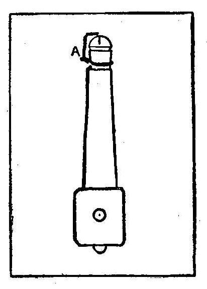
It is probably well known that if you rub your feet briskly over
a carpet on a dry, cold day and then touch any metallic object
with your finger it will emit a small spark. The following
amusing experiment may be done on the same principle:
Take any small piece of wire about 2 in. long and twist it around
a gas burner as shown at A in the sketch. Have the tip of the
burner about 1/8 in. below the end of the wire. The wire must be
just far enough away from the center of the burner to keep it out
of the flame, or else it will melt.
Now get a friend to turn on the gas when you are ready for it. Go
around the room once or twice rubbing your feet along the carpet.
When you come around to the gaslight touch the point of the wire
and if the gas is turned on, the light will flare right up as if
it had been lit with a match.
This experiment cannot be done on a damp day or without shoes,
and works best in cold weather.
Contributed by E. H. Klipstein.
How To Make a Trap For Rabbits, Rats and Mice
A Good Trap for Small Animals
From an old 6-in. pine fence board cut off four pieces 2-1/2 ft.
long and one 6 in. square for the end of the trap and another 4
in. by 8 in. for the door. Use old boards, as new boards scare
rabbits.
Figure 1 shows how the box is made. It should be 4 in. wide and 6
in. high on the inside. The top and bottom boards project 1 in.
beyond the side boards at the back and the end board is set in.
The top board should be 2 in. shorter than the sides at the
front. Nail a strip on the top board back of the door and one on
the bottom board so the game cannot push the door open from
inside the trap and get out.
In the middle of the top board bore a hole and put a crotched
stick in for the lever to rest on. Bore another hole in the top
of the door for the lever to pass through. Two inches from the
back of the box bore a hole for the trigger, which should be made
out of heavy wire in the manner shown in Fig. 2. The door of the
trap must work easily and loosely.
Novel Electric Motor
Novel Electric Motor
The materials necessary to make this motor are an old electric
bell of the “buzzer” type and a cogwheel from an old clock.
Remove the hammer-head and gong from the bell, then bend the end
of the hammer into a loop, as in Fig. 1. Now make a little wire
catch like Fig. 2, and fasten its loop into the loop of the
hammer. Mount the bell on a small board as in Fig. 3 and fasten
the cogwheel almost on a line with it. Now press down the hammer
and place a nail in the position shown in the diagram so that the
catch touches one of the teeth.
Fasten the board in an upright position and attach two dry
batteries to the binding-posts. If properly connected, the
fly-wheel will turn quite rapidly and with amazing force for so
small a machine. The machine, however, has a fixed direction as
shown by the arrow, but the belting can be arranged so as to send
the models in a reversed direction if required. The materials for
the motor should not cost more than 25c for the bell and if you
have an old bell it will cost next to nothing.
Contributed by Fred C. Curry, Brockville, Ontario.
How to Print Photographs on Silk
Silk, satin or any other fine material can be used to make
photographic prints, but the most attractive results for the
amateur are obtained on silk, the best color for this purpose
being either cream or white, says Photography. The chemicals
required are only four in number, and a comparatively small
amount of each will suffice, so that the process can be tried
without any very great outlay.
A dram of dextrine is mixed with 2 oz. of water and allowed to
dissolve. It is then made up to 4 oz. with boiling water, and,
when cold, a solution of 1 dr. of ammonium chloride in 2 oz. of
water is added. As this mixture does not keep well, it should be
used as soon as possible after being made up.
The silk is soaked in the liquid until it is thoroughly
saturated, which should take about four or five minutes, and it
is then hung up to dry, suspending it, tightly stretched, from
its two top corners. The fabric when “salted,” as this operation
is termed, will keep indefinitely. All these operations can be
done in daylight.
The next stage is the application of the sensitizer, for which
purpose the two following solutions must be made up and then
mixed:
| Silver nitrate | 120 gr. |
| Water | 1 oz. |
| Citric acid | 50 gr. |
| Water | 1 oz. |
The mixture is spread evenly over the silk with a soft
camel’s-hair brush. There must be no metal in the mounting of the
brush that is used.
Particular care must be taken to see that no particle of the
surface of the silk is left uncovered. The best way to insure
this is to brush the liquid over the silk, first in one direction
and then crosswise. The process of sensitizing must be done in a
weak artificial light, such as at night by ordinary gas or lamp
light, or in the very feeblest daylight.
The silk is then again fastened up and allowed to dry, but it is
now sensitive to the light and the drying must therefore be done
in the dark. It is ready for printing as soon as it is dry, and
as it does not keep well in the sensitive condition, it should be
used up within a few days at the most.
The printing, which is done in daylight, is carried on in the
same way as for printing-out papers, except that the silk should
be printed a little darker than usual. It will be found
convenient to gum the edges slightly, and then to fix the silk on
a stiff piece of paper before putting it into the printing frame.
If this precaution is not adopted there is a tendency for the
silk to slip or crease when it is being examined. The silk must
be handled carefully while in the printing frame for this reason,
but apart from that, there is no particular difficulty. The paper
can be taken off when the printing is finished.
Prints on silk are toned, fixed and washed in the same way as
ordinary silver prints. The washing should be thorough, and
before the prints are quite dry, they should be ironed to remove
all creases.
Removing Old Paint
A chair more than a hundred years old came to me by inheritance.
It was originally painted green and had been given two coats of
dark paint or varnish within the last 30 years. Desiring to
improve the appearance of the relic, I decided to remove the
paint and give it a mahogany stain. The usual paint removers
would readily take off the two latter coats but had no effect
upon the first. I tried to remove the troublesome green in
various ways, but with little success until I applied a hot,
saturated solution of concentrated lye.
By coating the paint with
this repeatedly, applying one coat upon another for two days, and
then using a stiff brush, the layer was easily and completely
removed.
Contributed by Thos. R. Baker, Chicago, Ill.
A Window Lock
Bore a hole through the sash of the lower window and halfway
through the sash of the upper window, where they meet in the
center, and insert a heavy nail or spike. This will fasten the
sash together so well that nothing short of a crowbar can pry
them apart. The nail can be easily removed when the windows are
to be opened.
Homemade Magnifying Glass
A very good magnifying glass can be made from an ordinary
incandescent lamp of about 16-cp. size which has been rendered
useless by being burned out or having the filament broken. Grind
or break off the tip end of the globe and fill with water. Put in
clear water and plug or cork up the hole.
Trailer for a Bicycle
Fig. 1—Trailer Attached to a Bicycle
Fig. 2-The Hook in Position
Instead of using a seat on the handlebars or frame of a bicycle
for my little girl, I made a trailer, as shown in Fig. 1, to
attach to the rear axle. I made it from old bicycle parts. The
handlebars, which form the back of the seat, fasten into the seat
post of an old bicycle attached to the trailer axle. The trailer
is attached to the rear axle of the bicycle with two arms or
forks, on the ends of which are two forgings, formerly used on
the rear ends of a bicycle frame, brazed in, and one of the tube
projections cut off from each to make a hook, as shown in Fig. 2.
The piece marked E shows one of these forgings or hooks in
section. The original axle of the bicycle was removed and one
1-5/16 in. longer supplied, which was turned below the threads
for clearance, as shown at A. A washer, D, with a hexagon hole
was fitted over the regular nut C, on the axle, and filed
tapering so the forging or hook E, on the trailer attachment,
could be kept in position. The washer F is held tightly against
the hook by pressure from a spring, G. The spring is held in
place by a small nut, H, and cotter pin, I. This attachment makes
a flexible joint for turning corners. When turning from right to
left the left hook on the trailer fork stays in position, while
the right hook pushes the washer F outward and relieves the
strain on the fork. This attachment also makes it easy to remove
the trailer from the bicycle. The washers F are pushed outward
and the hook raised off the axle.
Contributed by John F. Grieves, Providence, R. I.
Home-Made Telephone Transmitter
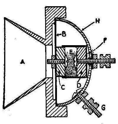
The parts for transmitting the sound are encased in a covering,
H, made from the gong of an old electric bell. A round button, D,
is turned or filed from the carbon electrode of an old dry cell
and a hole drilled through the center to fit in a binding-post
taken from the same battery cell. This button must be carefully
insulated from the shell, H, by running the binding-post through
a piece of small rubber tube where it passes through the hole and
placing a rubber or paper washer, F, under the carbon button, and
an insulating washer under the nut on the outside. This will
provide one of the terminals of the instrument. Construct a paper
tube having the same diameter as the button and with a length
equal to the depth of the bell case, less 1/8 in. Glue or paste
this tube to the button so it will form a paper cup with a carbon
bottom.
The diaphragm, B, which is the essential part of the instrument,
should be made as carefully as possible from ferrotype tin,
commonly called tintype tin. Cut a circular piece from this metal
the exact size of the outside of the shell. A hole is made in the
center of the disk a little larger than a binding-post that is
taken from another old battery cell. When making the hole in the
disk be careful not to bend or crease the tin. Scrape the black
coating from the tin around the outside about 1/4 in. wide and a
place about 1 in. in diameter at the center.
The second electrode, C, is made the same as D, and fastened to
the tin diaphragm with the binding post without using any
insulation. A third binding post, G, is fastened to the shell
through a drilled hole to make the other terminal. The
mouthpiece, A, may be turned from wood in any shape desired, but
have a flange on the back side that will make a tight fit with
the outside of the shell.
Fill the paper tube with powdered carbon, E, which can be made by
pounding and breaking up pieces of carbon to about the size of
pin heads. Powdered carbon can be purchased, but if you make it
be sure to sift out all the very fine particles. Assemble the
parts as shown and the transmitter is ready for use. If speech is
not heard distinctly, put in a little more, or remove some of the
carbon and try it out until you get the instrument working
nicely.
Contributed by Harold H. Cutter, Springfield, Mass.
Quickly Made Lawn Tent
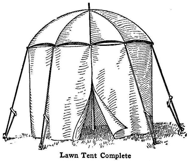
Lawn Tent Complete
A very simple way of erecting a lawn tent for the children is to
take a large umbrella such as used on delivery wagons and drive
the handle into the ground deep enough to hold it solid. Fasten
canvas or cotton cloth to the ends of the ribs and let it hang so
that the bottom edge will touch the ground. Light ropes can be
tied to the ends of the ribs and fastened to stakes driven in the
ground in a tent-like manner to make the whole more substantial
and to stand against a heavy wind. This makes an exceptionally
fine tent, as the umbrella is waterproof; also, there is more
room to stand up in than in a tent that is in the shape of a
wigwam.
Contributed by J.A. Whamer, Schenectady, N. Y.
How to Make a Windmill of One or Two Horsepower for Practical Purposes
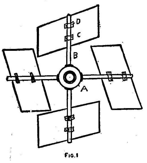
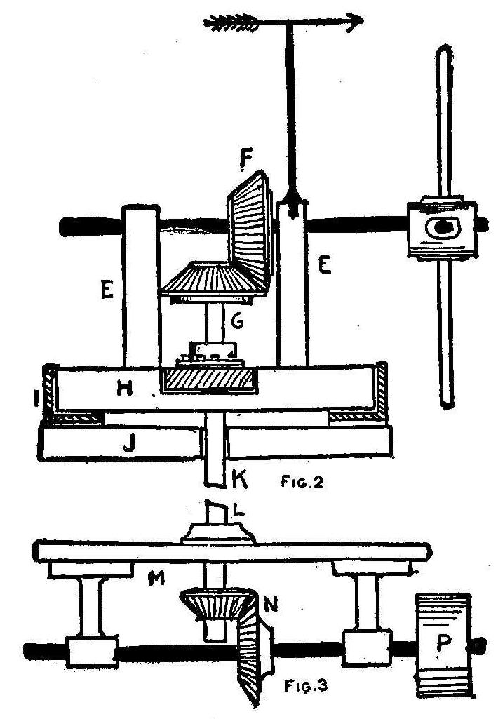
A windmill for developing from 1/2 to 2 hp. may be constructed at
home, the expense being very small and the results highly
satisfactory.
The hub for the revolving fan wheel is first constructed. One
good way to get both the hub, lining, shaft and spokes for the
blades, is to go to a wheelwright’s and purchase the wheel and
axle of some old rig. There are always a number of discarded
carriages, wagons or parts thereof in the rear of the average
blacksmith’s shop. Sometimes for half a dollar, and often for
nothing, you can get a wheel, an axle, and connected parts.
Remove from the wheel, all but the four spokes needed for the
fans as in Fig. 1. The same hub, axle and bearings will do. In
case you cannot secure a wheel and shaft, the hub may be made
from a piece of hardwood, about 4 in. in diameter and 6 in. long.
A 2-in. hole should be bored through for a wooden shaft, or a
1-1/2-in. hole for a metal shaft. The hub may be secured by
putting two or three metal pins through hub and shaft. Adjust the
spokes by boring holes for them and arrange them so that they
extend from the center A, like B. The wheel is then ready for the
blades. These blades should be of sheet metal or thin hardwood.
The sizes may vary according to the capacity of the wheel and
amount of room for the blades on the spokes. Each one is tilted
so as to receive the force of the wind at an angle, which
adjustment causes the wheel to revolve when the wind pressure is
strong enough. Secure the blades to the spokes by using little
metal cleats, C and D. Bend these metal strips to suit the form
of the spokes and flatten against the blades and then insert the
screws to fasten the cleats to the wood. If sheet metal blades
are used, rivets should be used for fastening them.
The stand for the wheel shaft is shown in Fig. 2. Arrange the
base piece in platform order, (J). This is more fully shown in
Fig. 5. On top of this base piece, which is about 36 in. long,
place the seat or ring for the revolving table. The circular seat
is indicated at I, Fig. 1. This ring is like an inverted cheese
box cover with the center cut out. It can be made by a tinner.
Size of ring outside, 35 in. The shoulders are 4 in. high and
made of tin also. Form the shoulder by soldering the piece on.
Thus we get a smooth surface with sides for the mill base to turn
in so as to receive the wind at each point to advantage. The
X-shaped piece H rests in the tin rim.
{400}
The X-form, however, does
not show in this sketch, but in Fig. 5, where it is marked S.
This part is made of two pieces of 2-in. plank, about 3 in. wide,
arranged so that the two pieces cross to make a letter X. When
the pieces join, mortise them one into the other so as to secure
a good joint. Adjust the uprights for sustaining the wheel shaft
to the X-pieces as shown at E, E, Fig. 2. These are 4 by 4 in.
pieces of wood, hard pine preferred, planed and securely set up
in the X-pieces by mortising into the same. Make the bearings for
the wheel shaft in the uprights and insert the shaft.
The gearing for the transmission of the power from the wheel
shaft to the shaft calculated for the delivery of the power at an
accessible point below must next be adjusted. The windmill is
intended for installation on top of a building, and the power may
be transmitted below, or to the top of a stand specially erected
for the purpose. It is a good plan to visit some of the
second-hand machinery dealers and get four gears, a pulley and a
shaft. Gears about 5 in. in diameter and beveled will be
required. Adjust the first pair of the beveled gears as at F and
G. If the wheel shaft is metal, the gear may be set-screwed to
the shaft, or keyed to it. If the shaft is hardwood, it will be
necessary to arrange for a special connection. The shaft may be
wrapped with sheet metal and this metal fastened on with screws.
Then the gear may be attached by passing a pin through the
set-screw hole and through the shaft. The upright shaft like the
wheel shaft is best when of metal. This shaft is shown extending
from the gear, G, to a point below. The object is to have the
shaft reach to the point where the power is received for the
service below. The shaft is shown cut off at K. Passing to Fig. 3
the shaft is again taken up at L. It now passes through the
arrangement shown, which device is rigged up to hold the shaft
and delivery wheel P in place. This shaft should also be metal.
Secure the beveled gears M and N as shown. These transmit the
power from the upright shaft to the lower horizontal shaft.
Provide the wheel or pulley, P, with the necessary belt to carry
the power from this shaft to the point of use.
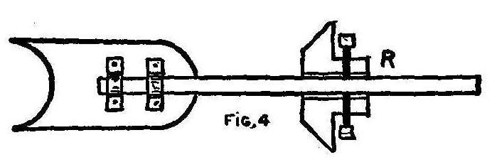
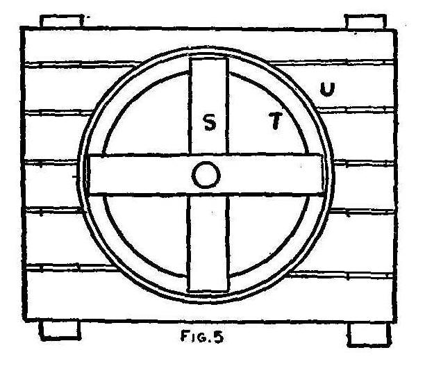
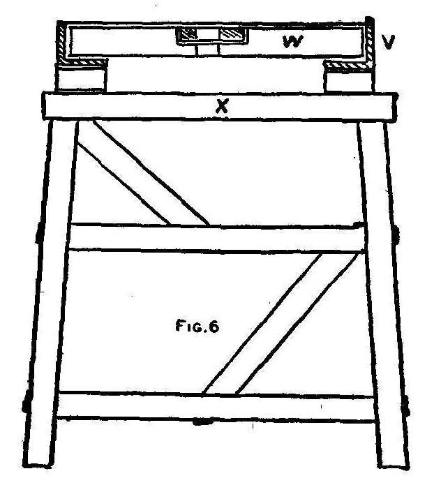
The tail board of the windmill is illustrated in Fig. 4. A good
way to make this board is to use a section of thin lumber and
attach it to the rear upright, E of Fig. 2. This may be done by
boring a hole in the upright and inserting the shaft of the
tail-piece. In Fig. 4 is also shown the process of fastening a
gear, R, to the shaft. The set screws enter the hub from the two
sides and the points are pressed upon the shaft, thus holding the
gear firmly in place. The platform for the entire wheel device is
shown in Fig. 5. The X-piece S is bored through in the middle and
the upright shaft passes through. The tin run-way or ring is
marked T, and the X-piece very readily revolves in this ring,
whenever the wind alters and causes the wheel’s position to
change. The ring and ring base are secured to the platform, U.
The latter is made of boards nailed to the timbers of the staging
for supporting the mill. This staging is shown in Fig. 6, in a
sectional view. The ring with its X-piece is marked V, the
X-piece is marked W, and the base for the part, and the top of
the stage is marked X. The stage is made of 2 by 4-in. stock. The
height may vary, according to the requirements. If the affair is
set up on a barn or shed, the staging will be sufficient to
support the device. But if the stage is constructed direct from
the ground, it will be necessary to use some long timbers to get
the wheel up high enough to receive the benefit of the force of
the wind. Proceeding on the plan of the derrick stand, as shown
in Fig. 6, a stage of considerable height can be obtained.
To Renew Old Dry Batteries
Remove the paper that covers the cell and knock several
good-sized holes in the zinc shell. Place the battery in a glass
jar, fill it two-thirds full of strong sal ammoniac (or salt)
solution and connect the terminals to whatever apparatus the
current is to be used for. A few drops of
sulphuric acid quickens
and improves the action. The output of the cell will be nearly as
great as when the battery was first bought.
Contributed by C. W. Arbitt, Austin, Texas.
Blue Dye
Prussian blue and Chinese blue are both the same chemically but
they do not cut or look the same.
Acetylene lamp
When an acetylene lamp is in good
order it will light up slowly with a hissing noise followed by a
pure white flame. Should the lamp light up quickly with a
yellowish flame, it is a sign of a leak somewhere.
Another Electric Motor
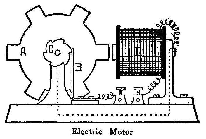
Electric Motor
This form of electric motor is used largely in England in the
form of an indicator. It is very easily made and if you have an
old electro-magnet will cost practically nothing.
A large soft-iron wheel is mounted on an axle with a pulley-wheel
on one end and a circuit breaker on the other end. The teeth on
the circuit-breaker must be the same number as on the soft-iron
wheel.
The electro-magnet is mounted so that its core is level with the
axle and in a line with the wheel. One wire from it is attached
to one binding screw and the other end is grounded to the iron
frame that supports it. This frame is connected to the frame
supporting the wheel. A small brush presses on the circuit-breaker
and is connected to the other binding screw.
In the diagram A represents the iron wheel; B, the brush; C, the
circuit breaker; D, the magnet. The wire connecting the two
frames is shown by a dotted line.
To start the motor, attach your battery to the screws and turn
the wheel a little. The magnet attracts one of’ the teeth on the
wheel, but as soon as it is parallel with the core of the magnet
the circuit is broken and the momentum of the wheel brings
another tooth to be attracted.
To reverse the motor reverse the connections and start the wheel
the other way. Be sure that the frames are screwed down well or
the motor will run jerkily and destroy the connections.
Contributed by F. Crawford Curry, Brockville, Ontario.
How to Make a Propelling Vehicle
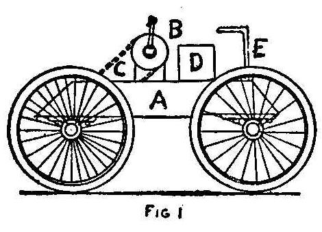
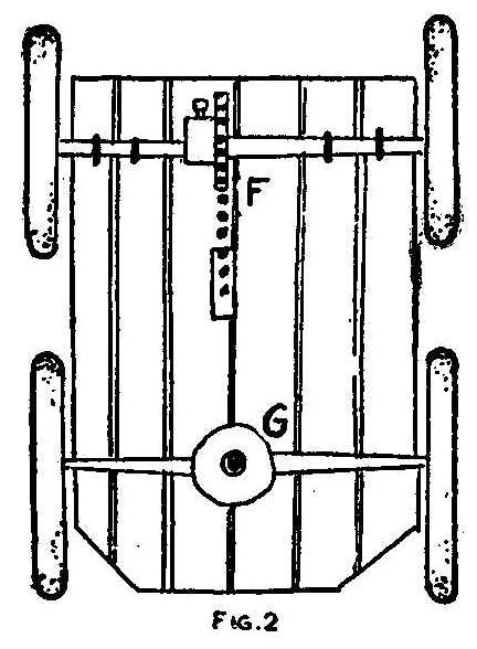
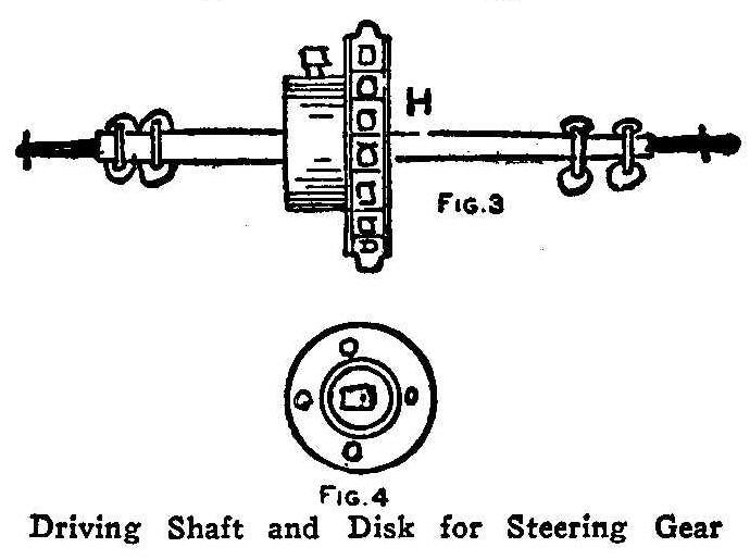
Driving Shaft and Disk for Steering Gear
Any boy, with a little knack and a few odd tools, can rig up
various contrivances which will be a source of pleasure to
himself and oftentimes can be sold, to less ingenious boys, for a
snug little sum. Any tool a boy can obtain is apt to be of use to
him, chisel, bit, jack-knife or hammer.
Figure 1 shows what two boys did with old cycle wheels. They went
to some junk shops where the concerns had purchased cast-away
bicycles and noticed that there were numerous wheels in very good
order that could be selected from among the sets of wheels with
broken or bent rims, spokes, burst tires, etc. In fact, the lads
had no trouble in getting several sets of bicycle wheels in good
condition for very little money. These wheels were taken to the
back-yard shop of the boys where the young fellows had rigged up
a shed-like affair and put in a bench. The previous Christmas one
of the boys received a box of tools as a gift, in which was
included a little hand vise and the required tools for general
boy’s handiwork.
Four of the cycle wheels they used in making the hand-propelled
vehicle shown at Fig. 1.
A wooden body, A, made of smooth boards rests upon shafts. Fixed
on this body is an upright carrying the sprocket B. The upright
is a piece of wood about 10 in. high and 4 in. wide, fitted with
one of the bearings from the cycle. The regular cycle chain
sprocket is used at B as well as upon the shaft. The regular
chain of the cycle is likewise employed, so, when buying the
wheels, it is well to select one or more chains with
corresponding sprockets from the junk heap. The detail of the
adjustment of the parts is shown in next views. The letter D
signifies the seat which is a box. The steering gear is a bent
iron rod, also found in the waste pile of the junk shop, and is
bent to right form by heating and bending over on a rock or any
solid matter. The steering rod is marked E. It fits into a socket
in the shaft of the forward wheels.
Figure 2 shows the construction of the cart below. The cog is
keyed or set-screwed to the driving shaft of the wheels with
either key or set-screw used in original fastening, as the case
may be. The chain is marked F, and there is a slot cut in the
floor of the cart to let the chain pass up and through to the cog
on the propelling shaft crank. The disk which receives the
steering rod is at G. The forward shaft bears only at the center
upon a disk of metal, consisting of any circular piece found
among the pieces of iron or brass at the junk store. One can get
nearly all the mechanical parts in junk establishments that
purchase parts of out-of-date or cast-away bicycles. The detail
of the driving shaft is shown at Fig. 3. The sprocket wheel is at
H and this is just as it is taken from the original bicycle
shaft. The bearings consist of wires looped around the shaft and
inserted into holes bored in metal plates as shown. These plates
are screwed to the bottom of the cart. The shaft itself is found
in rods or even cast-away metal axles which are commonly found in
most any carriage works, cycle shops or junk dealer’s. Figure 4
shows the disk that receives the steering gear. The disk is bored
around edges for the securing screws, while the center is open
for the steering rod. When put together, three boys usually ride.
One steers and the other two turn the crank. Freight can be
carried and some boys do quite an express business in their town
with one of the carts like this that they made.
Ringing a Bell by Touching a Gas Jet
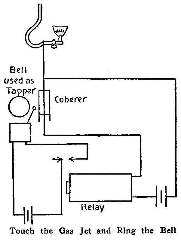
Touch the Gas Jet and Ring the Bell
The experiment of scuffling the feet over a carpet and then
producing a spark which will light the gas by touching the
chandelier is described on another page. One of our
correspondents says that if a wire is connected to the chandelier
and led to one terminal of the coherer of a wireless telegraph
outfit the bell will ring every time the spark is produced by
touching the chandelier, and that, as the chandeliers are all
connected by the gas-pipe, the bell will ring, no matter in which
room the spark is produced.
Lead Kills Knots
The covering quality will be greatly improved if some dry red
lead is added to the
shellac varnish used for killing knots.
How to Make a Wood Turning Lathe Out of an Old Sewing Machine
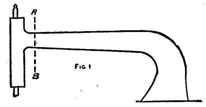
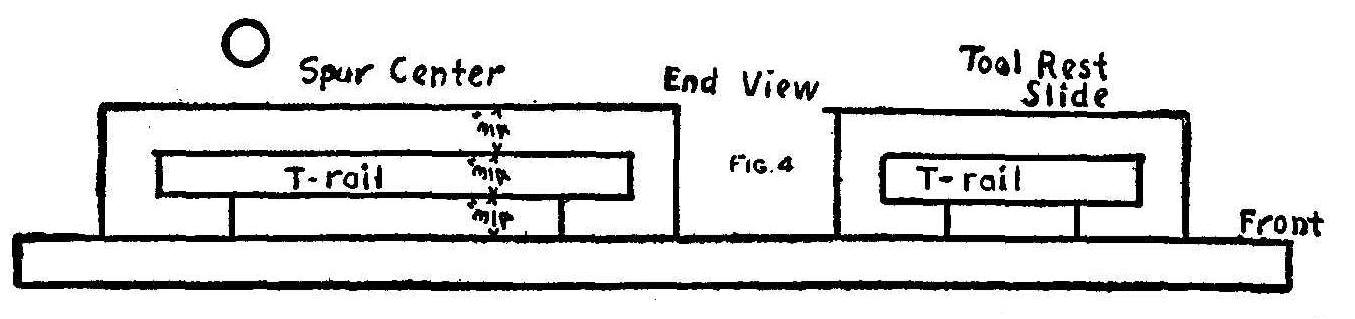
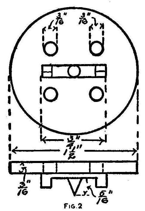
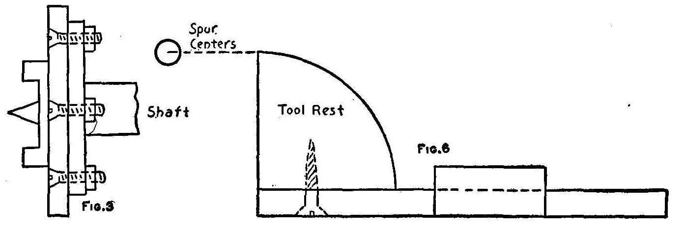
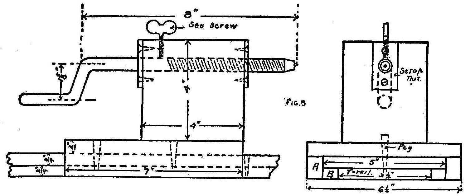
With a hack-saw, cut off the arm containing the needle on line
AB, Fig. 1, leaving the shaft only. On the end of the shaft will
be found a round plate, in which drill four 3/16-in. holes. Now
secure, or have turned, a piece of iron or steel 1-1/2 in. in
diameter, Fig. 2. Drill and countersink four 3/16-in. holes in it
to fit the holes on the shaft plate. File a spur center 5/16 in.
long, and two side points 3/16 in. long. Bolt this plate to the
shaft plate with four flat-headed stove bolts, 3/16 in. in
diameter by 5/8 or 3/4 in. long, Fig. 3.
For the bed, use a board 32 in., long and as wide as the base of
the machine arm. This gives a limit of 2 ft. between spur and
dead centers. Let this board be made level with the rest of
machine table by making a pair of legs if needed. Next make a
T-rail, Fig. 4, of two boards, one 5 by 3/4 by 32 in., the other
3-1/2 by 3/4 by 32 in. Three-quarter inch of the wider board
projects over each of the smaller boards. Nail firmly and clinch
nails, or screw together. Screw this rail on the machine board so
that its center coincides exactly with the machine centers. Bore
a number of 3/8-in. holes with centers 2-3/4 in. apart along the
center line of this rail, beginning 6 in. from the end nearest
the machine. Make another T-rail for slide tool rest, of two
pieces 32 by 3 by 3/4 in., and 32 by 1-1/2 by 3/4 in. Fasten this
in front of the larger T-rail and parallel to it, the center
lines being 6-1/2 in. apart.
To make the tail-piece, that is, the part to hold wood to be
turned, get a board 6-1/2 by 7 by 3/4 in., and on the edges, Fig.
5, A, screw two pieces 7 by 3/4 by 1-1/2 in. so that the cap thus
made will fit snugly over the large T-rail.
{404}
Fasten to these last
two pieces, with screws, two more pieces 7 by 3/4 by 3/4 in.,
Fig. 5, B. This tail-piece should move smoothly back and forth
with no side motion. Now get a block of hardwood 4 by 2-1/4 in.,
and 1-3/4 in. higher than the spur center when mounted on the
middle of the tailpiece just described. At exactly the height of
the spur center bore through this block a 3/4-in. hole, Fig. 5.
Have a blacksmith make a crank 8 in. long, threaded for 5 in. as
shown. At the dead center end taper the crank and make a cup
center, out of which allow a 3/16-in. point to project. The cup
prevents the point from boring into wood too rapidly. One inch
from the outer end of the crank block, Fig. 5, bore a 3/16-in.
hole, and force a 1/4-in. bolt to cut its thread in the wood.
This is a set screw to hold the crank in any position desired.
Place a strap nut, threaded to fit the crank, on the headend of
the crank block, and a plain nut to act as a bearing, on the
crank end. One and one-half inches from the back of the
tail-piece bore a 3/8-in. hole. Make a peg 3/8 by 2 in. To put in
a piece of wood to turn, move the tailpiece back until the head
end is over the center of the hole nearest the end of the block,
then the peg will slip into second hole from the head end of the
tail-piece, and into a corresponding T-rail hole, pinning the two
together. Insert wood and screw up dead center to hold it.
For a tool rest make a second piece like the base of the
tail-piece, 11 in. long and fitting the small T-rail. Cut out two
blocks 1-1/2 by 2-1/4 by 3/4 in. and screw them, one on each end
of the base of the tool rest, covering the half farthest from the
centers, and having an 8-in. space between blocks. On the tops
of these blocks screw a strip 11 by 2-1/4 by 3/4 in. Now for the
rest proper, cut out a board 8 by 11/16 by 9 in. to slide in the
slot of the rest. Take a piece of oak 11 by 2 in., and high
enough so that the top will be level with the centers of the
lathe, and bevel as shown in Fig. 6. Screw on one end of the 8 by
9-in. piece exactly in the middle. This piece will slide in and
out, closer or farther from the centers as desired, and also
along the T-rail.
A center for turning rosettes, saucers, etc., may be made as
follows: Remove the spur center and bolt in its place a 1-in.
circular board of the same diameter, using longer 3/16-in. stove
bolts with heads countersunk. Rotate the lathe, and with a gimlet
bore a hole at the exact center and through the board. Now take
off the board and countersink on the back a place for the head of
a coarse threaded screw. Turn in a 1-3/4-in. screw, replace the
board and any block held on the end of the rotating screw will
turn on and be held while being turned.
Contributed by L. L. Winans, Mexico, Mo.
Reversing Small Battery Motor
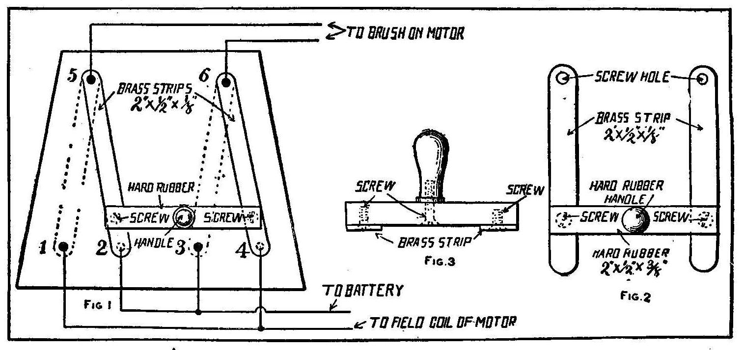
Make the switch out of a piece of slate (for the base) two strips
of brass, a rubber strip and handle and some binding-posts from
old dry batteries. Fasten the brass strips at 5 and 6, Fig. 1, so
they can swing from 1 and 3 to 2 and 4. Hold the brass strips
apart by means of the hard rubber strip and screws. Do not let
the screws come all the way through the rubber strip or you are
liable to get a shock in case you should touch both screws
simultaneously. Screw a rubber handle onto the rubber strip to
move the lever back and forth with. Fig. 2 shows the arrangement
of strips, handle, screws, etc., in detail. Fig. 3 is an end view
of the same.
Contributed by Eugene F. Tuttle, Jr., Newark, Ohio.
Cleaning Bronze Bearings
Bronze bearings may be cleaned with a solution of washing powder
and water run through the oil cups while the machine is running
without any load. The solution, cutting out the dirt and grime,
will come from the bearing very black. About 1 pt. of this
mixture should be run through each bearing, then clean thoroughly
with clear water.
A Water Candlestick
A glass of water makes a fine emergency candlestick. Weight one
end of the candle with a nail just large enough to hold the
candle in the water so that the water comes near its top edge,
but does not touch the wick, and then light the candle. It will
burn until the last vestige of wick is gone and the flame will
not flicker. The melted tallow that runs down but serves to hold
the candle more stationary.
How to File Soft Metals
When filing soft metals, such as solder or babbitt metal, the
file, after a few strokes, will become filled with metal, causing
scratches on the surface being filed. The surface may be filed
smooth, provided the file has been well oiled. The oil prevents
the cutters from clogging and also allows the metal to yield
easily. Oil the file every few minutes and use a card frequently
in cleaning and the work will be smooth.
Contributed by Jno. E. Ganaway, Paducah. Ky.
To Make a Magazine Binder
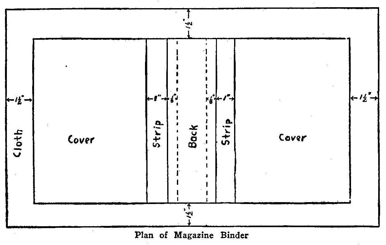
Plan for Magazine Binder
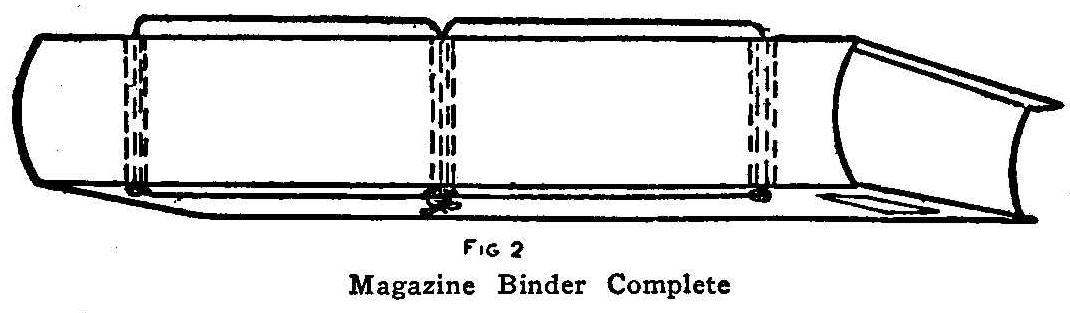
Magazine Binder Complete
Get 1/2 yd. of cloth, one shoestring, a pasteboard box for
covers, and some heavy paper. Cut the pasteboard into two covers,
1/4 in. larger all around than the magazine, except at the back
with which they should be even. Next cut a strip 1 in. wide off
the back of each cover. Place the covers on the cloth, Fig. 1,
with the back edges 1/4 in. farther apart than the thickness of
the volume to be bound. Cut the cloth around the covers, leaving
1-1/2 in. margin. Paste the cloth on the covers as they lay, and
turn over the 1-1/2 in. margin, pasting down smoothly. Cut a
piece of stiff paper to fit and paste on the back. Take a piece
of cloth as wide as the cover, and long enough to extend over the
back and 1-1/2 in. beyond each “strip.” Paste on to hold all
together. Two pieces of paper the exact size of the magazine,
pasted on the inside of each cover protects the edges of the
cloth, and adds to the appearance. Let dry slowly.
With backs and edges of magazines even, place in a vise and set
up tight allowing 3/4 in. from back to show above the vise. Bore
three 3/16-in. holes 1/2 in. from the back, one in the middle,
the other two 1-1/2 in. from each end. Make corresponding holes
in the strips of the binder and use the shoestring to complete as
in Fig. 2.
Temporary Spline
A piece of wire solder makes a good temporary spline for the
draftsman.
A Library Set in Pyro-Carving
By Helen Westinghouse
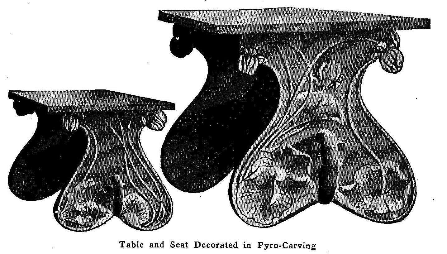
Table and Seat Decorated in Pyro-Carving
The multitude of indifferently executed small articles which
followed the introduction of pyrography is beginning to
disappear. People are considering the art more seriously and
applying it to more dignified uses. Pyro-carving is one of the
new methods of decorating furniture which is both beautiful and
practical, two qualities which do not always go together.
The library set illustrated consists of a table, 30 to 50 in.,
with two benches, 14 in. wide, of the same length. The supports
are made of selected white pine, which must be absolutely free
from pitch. The pine is soft enough to work easily with the point
and stands wear much better than basswood. The tops and braces
are made of curly fir. All of the material must be 2-in. lumber,
which dresses to about 1-1/2 in. All surfaces, except the faces
of the supports, are given a well rubbed coat of oil with a
little burnt umber, the stain to be applied directly to the wood
without a filler.
On the outside of the supports the design is drawn in with
pencil, the background is then cut out smoothly with a chisel to
the depth of an eighth of an inch, leaving the decoration in
relief. It is then burned deeply, the background in straight flat
strokes, the outlines having the effect of a sloping, dark edge.
The shadows are burned in as deeply as possible and the shading
is put in with the flat of the point. A wax or eggshell
oil-varnish finish is most suitable for this set, but any other
finish may be applied, as the builder may desire, to make it
harmonize with other furnishings.
Cleaning Brass
Small brass castings can be cleaned by heating them slightly and
then dipping them in a solution of sal ammoniac. The pieces will
come out as bright and clean as if new. This cleaning process is
the same as that used in cleaning a soldering iron.
A Phoneidoscope
The phoneidoscope has many and varied forms, but the simplest can
be made by bending the forefinger and thumb so as to form a
circle and then drawing a soap film across the opening. This is
done in a manner similar to the blowing of soap bubbles. The
angle with the direction of the light may be readily adjusted by
turning the wrist, a motion of the elbow alters the distance from
the mouth and the tension of the film can be regulated by moving
the thumb and forefinger. Singing or speaking at the film when
under proper tension will cause beautiful figures to appear,
which may be reflected from the film directly on the screen.
Contributed by Robt. E. Bradley, Winchester, Mass.
A Home-Made Yankee Bobsled
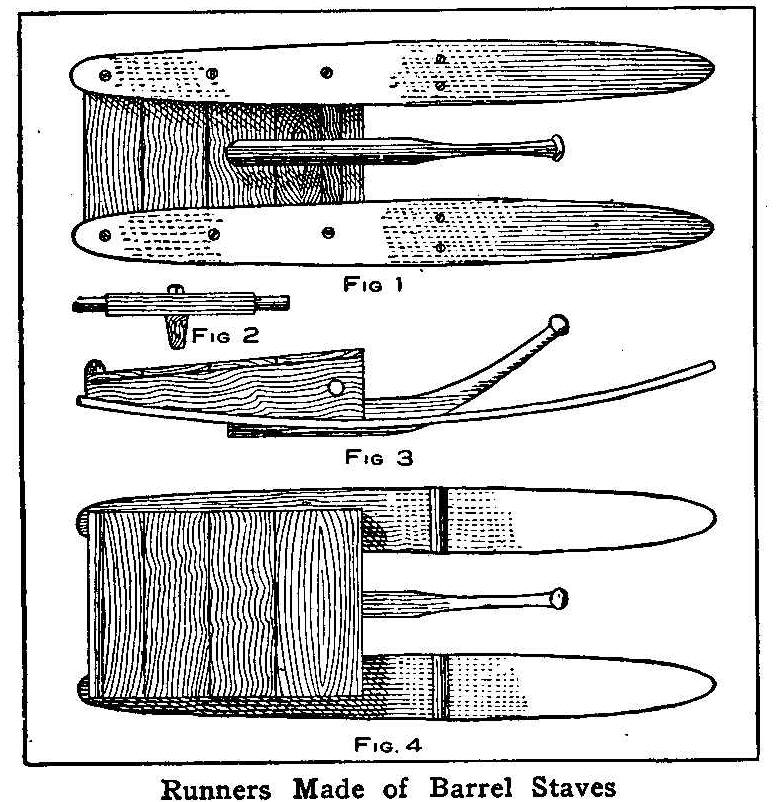
Runners Made of Barrel Staves
A good coasting sled, which I call a Yankee bob, can be made from
two hardwood barrel staves, two pieces of 2 by 6-in. pine, a
piece of hardwood for the rudder and a few pieces of boards. The
2 by 6-in. pieces should be a little longer than one-third the
length of the staves, and each piece cut tapering from the widest
part, 6 in., down to 2 in., and then fastened to the staves with
large wood screws as shown in Fig. 1. Boards 1 in. thick are
nailed on top of the pieces for a seat and to hold the runners
together. The boards should be of such a length as to make the
runners about 18 in. apart.
A 2-in. shaft of wood, Fig. 2, is turned down to 1 in. on the
ends and put through holes that must be bored in the front ends
of the 2 by 6-in. pieces. A small pin is put through each end of
the shaft to keep it in place. The rudder is a 1-1/2-in. hardwood
piece which should be tapered to 1/2 in. at the bottom and shod
with a thin piece of iron. A 1/2-in. hole is bored through the
center of the shaft and a lag screw put through and turned in the
rudder piece, making it so the rudder will turn right and left
and, also, up and down. Two cleats are nailed to the upper sides
of the runners and in the middle lengthways for the person’s
heels to rest against.
Any child can guide this bob, as all he has to do is to guide the
rudder right and left to go in the direction named. If he wants
to stop, he pulls up on the handle and the heel of the rudder
will dig into the snow, causing too much friction for the sled to
go any further.
Contributed by Wm. Algie, Jr., Little Falls, N. Y.
How to Make a Small Microscope
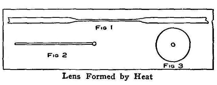
Lens Formed by Heat
Theoretically a simple microscope can be made as powerful as a
compound microscope, but in practice the minute size required by
the simple lens to give the highest power makes it almost
impossible to be used. However, a lens having a reasonable
magnifying power can be made in a few minutes for almost nothing.
Take a piece of glass tubing, heat one place in a hot flame, hold
one end and pull on the other and draw the heated place down to a
fine string as shown in Fig. 1. Take about 3 in. of this fine
tube and heat one end which will form a glass bead as shown in
Fig. 2. This bead is the lens. When in this form it can be used
only in an artificial light coming from one direction, but if you
take a piece of cardboard and bore a hole in it a little smaller
than the bead on the glass tube which is forced into the hole,
Fig 3, you can use this mounted lens in ordinary daylight. In
this case a mirror must be used to reflect the light up through
the lens. It is difficult to see anything at first, as the lens
must be held very close to the eye, but in practice you will soon
learn to see the object as it appears enlarged.
If you soak a little dried grass or hay in water for a few days
and look at a drop of this water, germs in various life forms can
be seen. The water must be put on the lens. One thing to remember
is that the smaller the lens, the greater the magnifying power.
Contributed by Daniel Gray, Decatur, Illinois.
Freezing Pipes
The water in hot water supply pipes will freeze quicker than
water that has not been heated. This is because the air, which is
a poor conductor of heat, has been driven out by the heat.
How to Carry Books
Almost all school children carry their books with a strap put
around and buckled very tight. This will make dents in the
cover where the board overlaps the body of the book. If the strap
is left loose, the books are liable to slip out. Place the cover
of one book between the cover and fly leaf of its neighbor and
the difficulty will be remedied. This will place the books in
alternate directions. Books stacked in this manner do not require
the strap buckled tight, or, they can be carried without any
strap just as well.
Contributed by Thos. De Loaf, Grand Rapids, Mich.
Bottle Pushers
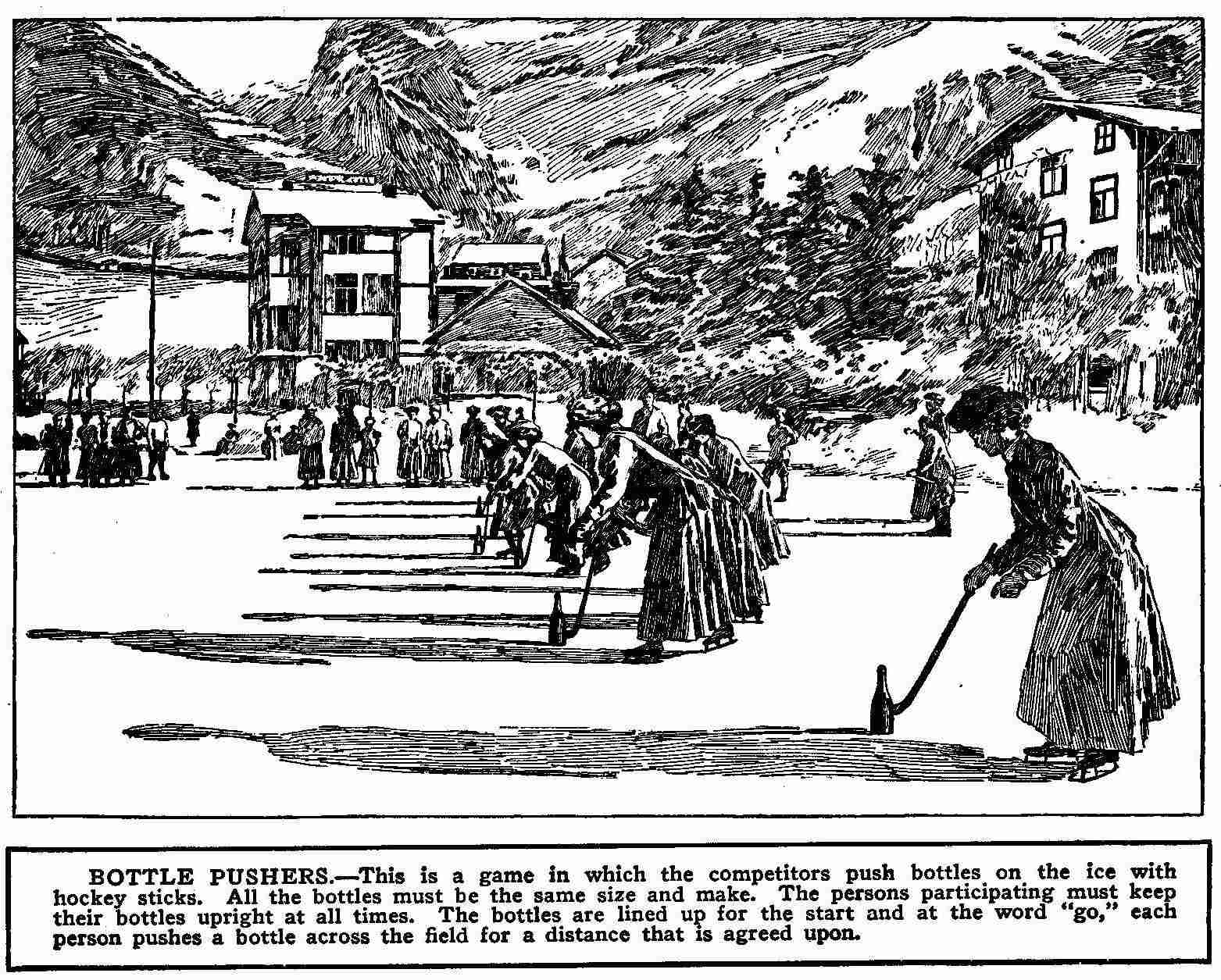
Bottle Pushers
This is a game in which the competitors push bottles on the ice
with hockey sticks. All the bottles must be the same size and
make. The persons participating must keep their bottles upright
at all times. The bottles are lined up for the start and at the
word “go,” each person pushes a bottle across the field for a
distance that is agreed upon.
How to Make a Hammock
Anyone can make a hammock as good as can be bought and that at a
cost so small that every member of the family can possess one
providing there are places enough for hanging them.
The materials required are a needle about 7 in. long, and with a
big eye, an iron ring for each end of the hammock, two long
smooth sticks on which to knit the hammock and two pounds of
strong hemp cord or twine. The twine may be colored in any color
or combination of colors desired. A Roman stripe at each end of
the hammock makes a pretty effect.
A hammock 45 in. wide will not be too large for solid comfort. To
knit it first thread the big needle and holding it in the left
hand, hold the cord in place with the thumb until you have looped
the cord over the tongue, then pass the cord under the needle to
the opposite side and catch it over the tongue. Repeat this
operation until the needle is full. Cut a 2-yd. length of cord
and make a loop and fasten to the door knob or to some other
convenient place. Tie the cord on the needle to this loop 3 in.
from the end of the loop. Place the small mesh stick under the
cord with the beveled edge close to the loop, and, with a thumb
on the cord to hold it in place, pass the needle around the stick
and then, point downward, pass it through the loop from the top,
and then bring it over the stick so forming the first half of the
knot.
Pull this tight and hold in place with a thumb while throwing the
cord over your hand, which forms the loop. Pass the needle from
under through the loops and draw fast to fasten the knot. Hold
this in place and repeat the operation. Make 30 of these knots
and then push them off the stick and proceed in the same way with
the next row, passing the needle first through each of the 30
knots made for the first row. Make 30 rows and then tie the last
loops to the other iron ring. Stretchers may be made and put in
place and the hammock, strong and durable, is finished. The work
must be carefully and evenly done. One is apt to have a little
trouble getting the first row right, but after that the work
proceeds quite rapidly.
How to Obtain Cheap Dry Batteries
Not very many people realize that good, serviceable dry cells can
be obtained from an automobile garage very cheap. These cells
having been “run out” beyond the required number of amperes for
automobile use, will give excellent service, considering their
cost. Many of them will give two-thirds of their original
amperage. Six of such cells have been in use on my door-bell
circuit for nearly a year. They can be used for other purposes
just as well.
Contributed by H. H. Cutter.
How to Make a Water Telescope
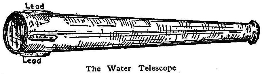
The Water Telescope
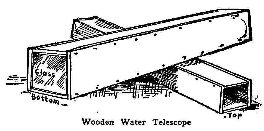
Wooden Water Telescope
Before you decide on a place to cast your hook it is best to look
into the water to see whether any fish are there. Yes, certainly,
you can look into the water and see the fish that are there
swimming about, if you have the proper equipment. What you need
is a water telescope. This is a device made of wood or metal with
one end of glass. When the glass end is submerged, by looking in
at the open end, objects in the water are made plainly visible to
a considerable depth. In Norway, the fishermen use the water
telescope regularly in searching for herring shoals or cod.
All that is necessary to make a wooden water telescope is a long
wooden box, a piece of glass for one end and some paint and putty
for making the seams watertight. Fix the glass in one end of the
box, and leave the other open to look through.
A tin water telescope is more convenient than the wooden one, but
more difficult to make, The principal essential for this is a
circular piece of glass for the large end. A funnel shaped tin
horn will do for the rest. Solder in the glass at the large end
and the telescope is made. Sinkers consisting of
strips of lead
should be soldered on near the bottom to counteract the buoyancy
of the air contained in the watertight funnel and also helps to
submerge the big end. The inside of the funnel should be painted
black to prevent the light from being reflected on the bright
surface of the tin. If difficulty is found in obtaining a
circular piece of glass, the bottom may be made square and square
glass used. Use plain, clear glass; not magnifying glass. To
picnic parties the water telescope is of great amusement,
revealing numerous odd sights in the water which many have never
seen before.
How to Rid Your Yard of Cats
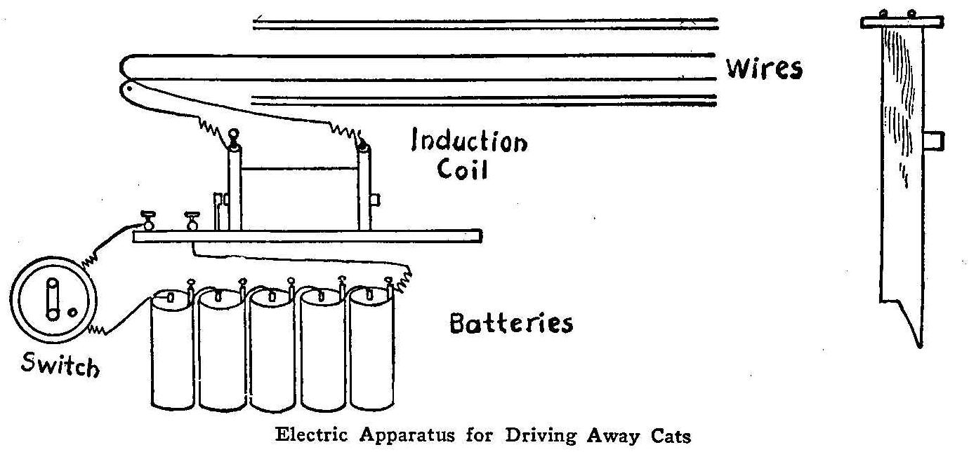
Electric Apparatus for Driving Away Cats
The following is a description of a device I built at my home in
Brooklyn, which not only gave us relief from the nightly feline
concerts, but also furnished much amusement to my friends. I
first ran two bare copper wires along the top of the fence about
1 in. apart, fastening them down with small staples, care being
taken that they did not touch. To the ends of these wires I
fastened ordinary insulated bell wire, running them to the house
and connecting them to the upper binding posts of an induction
coil; I then ran a wire from the lower binding-post of my coil
through the batteries back to the other lower binding-post of
coil, breaking the circuit by putting in an ordinary switch. The
more batteries used, the stronger the current. The switch should
always be left open, as it uses up the current very rapidly.
When “tabby” is well on the wires I close the switch and she goes
the length of the fence in bounds, often coming back to see what
the trouble is, thus receiving another shock.
Contributed by Charles L. Pultz.
Substitute for a Drill Bit
A gouge may be used as a substitute bit if a proper sized bit is
not at hand. The gouge can be placed in the brace the same as a
bit.
Drying Films
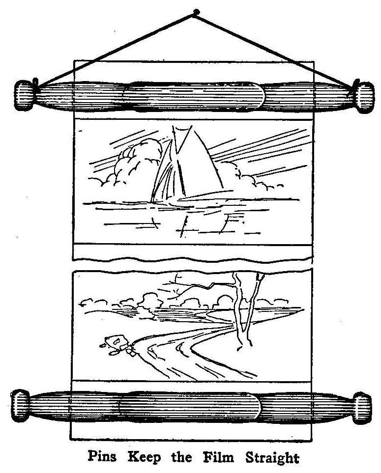
Pins Keep the Film Straight
The drying of photographic film in full lengths without
scratching or curling is quite difficult. Various devices are
used to keep the film straight, and push pins or thumb tacks are
supplied with almost all of them. The illustration shows a simple
and inexpensive device constructed of common wood clothespins
without any metal pins to come in contact with the film and cause
rust streaks. A pair of pins are fastened at each end of the film
by pushing one pin over the other which in turn is clamped on the
film. A string tied to the heads of one pair of pins provides a
way to hang the whole on a nail. The lower pair of pins makes a
weight to keep the film straight.
Contributed by J. Mac Gregor, Montreal, Canada.
Grooved Pulley Made from Sheet Tin
A grooved pulley which will run true and carry a round belt may
be made without the use of other tools than a compass and pair of
shears, with a drill or punch for making two rivet holes.
Lay off a circle on the tin, of the diameter desired for the
bottom of the groove. Then layoff a concentric circle of 1/4 in.
greater radius. Cut out along the lines of the large circle. On
the line of the small circle mark with a prick punch or nail a
series of slight dents, about 1/4 in. apart, all the way around.
Now make cuts from the line of the large circle to these dents,
stopping when the shears give the little “click” on entering the
dent. Bend the little tongues thus formed alternately to the
right and left, then by shaping them with some care you will have
a good running surface for the belt. It will not make any
difference if there are more tongues on one side than the other,
or if they are not equally spaced, within reason.
For the hub, solder or rivet a “handle” across the center hole
and drill a hole through it of the same size as the center hole.
With the help of solder a grooved pulley which will answer almost
every experimental purpose may be made, and it is remarkable with
how slight care a perfectly true wheel may be made in this
manner.
The same principle might in some way be applied to gear-wheels,
for light and temporary use.
Contributed by C. W. Nieman, New York City.
An Emergency Glass Funnel
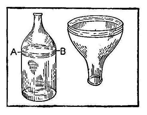
Secure a glass bottle having a small neck and tie a string
saturated in kerosene around the outside at A and B as shown in
the sketch. Light the string and allow it to burn until the glass
is heated, then plunge the bottle quickly into water. The top or
neck will then come off easily. The sharp edges are ground or
filed off smooth. This will make a good emergency funnel which
serves the purpose well for filling wide necked
bottles.
Contributed by Jos. W. Sorenson, Everett, Wash.
An Electrical Walking Stick
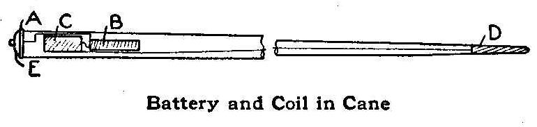
Battery and Coil In Cane
A cane that will produce an electric shock when shaking hands is
one supplied with the electrical apparatus shown in the sketch.
An ordinary cane, 1 in. in diameter at the top and having a metal
band A, is bored about 8 in. deep, to receive the battery B and
induction coil C. One of the electrical connections is through
the metal tip D to the earth, the other is through the metal band
A when the push button E is pressed.
The one using the cane merely holds the metal end D in contact
with the earth and while shaking hands with a friend he pushes
the button and starts the coil in operation.
Contributed by Stanley Radcliffe, Laurel, Md.
Convenient Shelf Arrangement
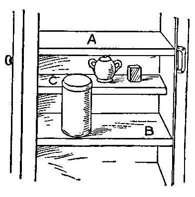
A convenient device for crowded shelves and cupboards is shown in
the accompanying sketch. Halfway between shelves A and B is
installed a second shelf C which is only half as wide as the
other shelves. This provides a convenient place for small
articles and utensils, while in a china closet it furnishes a
splendid space for cups, sauce dishes or other small pieces. It
also adds a neat and pleasing appearance.
Contributed by E. M. Williams, Oberlin, Ohio.
A Shoe Scraper
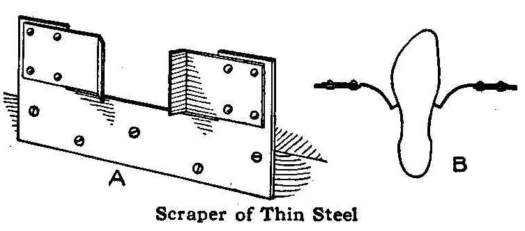
Scraper of Thin Steel
On steps of public buildings, shops and dwellings is usually
found some sort of a mud scraper for the shoes. These remove the
mud from the sole of the shoe and leave it on the edge and sides.
The scraper shown in the sketch is of simple construction, and
removes the mud from the soles and sides of any size shoe in one
operation. The scrapers spread and bring pressure to bear on all
sizes. The side scrapers must be made of metal that will spring.
The standard is of heavy sheet metal with the thinner strips
riveted to the projecting uprights at the ends.
Fastening a Shade to a Roller
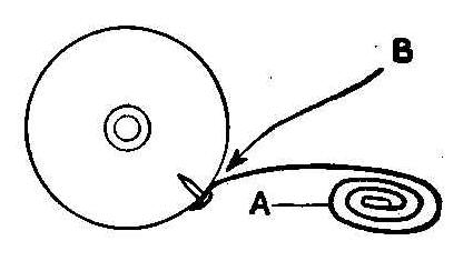
Tack the shade A in the usual manner and roll it as far back as
possible and while in this position apply an ample quantity of
glue near the tacks, as shown at B. A shade attached in this
manner will not come loose from the roller.
Vegetable Slicer
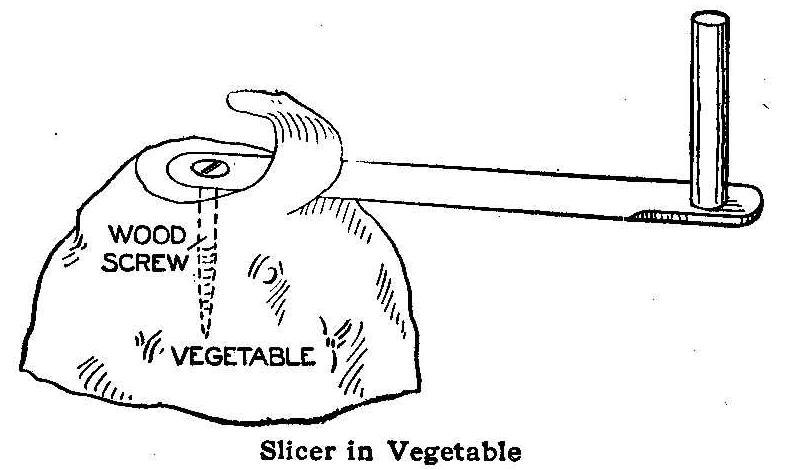
Slicer In Vegetable
The slicer is made of a knife blade, screw and pin handle. The
screw is soldered into the end of the knife blade. As the screw
feeds into the vegetable or fruit, the blade will slice it in a
curl of even thickness.
Contributed by H. C. Roufeldt, Toledo, O.
How to Make an Etched Copper Picture Frame
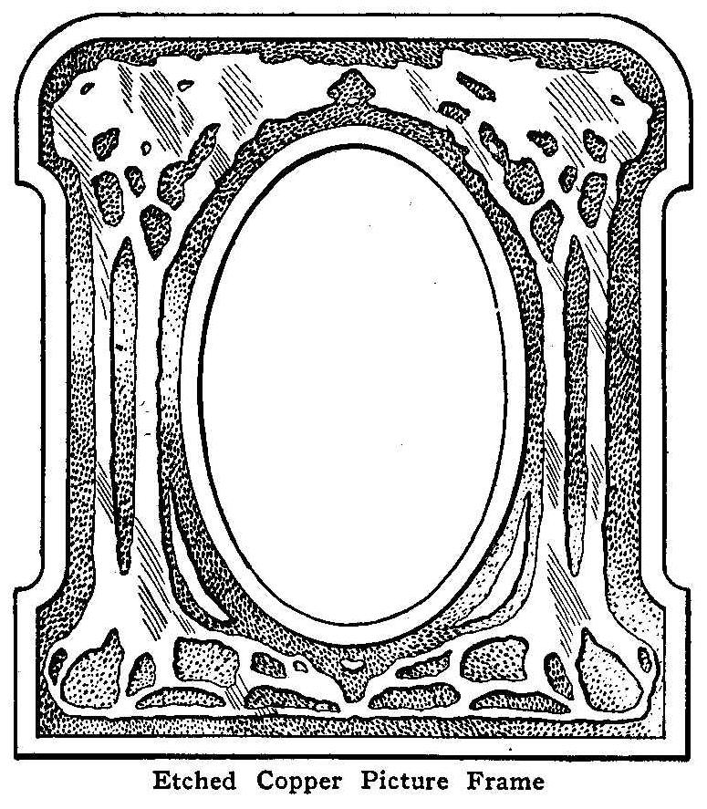
Etched Copper Picture Frame
Secure a heavy piece of copper about 8 or 10 gauge, cut to 7 by
7-3/4 in. Make a design on a piece of paper. The accompanying
sketch offers a suggestion. If the design is to be symmetrical,
draw a line down the middle of the paper, make one-half the fold
and trace the remaining half by placing a piece of
double-surfaced carbon paper between the halves. Fasten this
design with a little paste on the copper at two of its corners
and trace it on the copper by means of the carbon paper.
Remove the paper, and, with a small brush and black varnish or
asphaltum paint, cover the part not to be eaten by the acid of
the bath into which the metal is to be immersed. Two or three
coats will be necessary to withstand the acid. The conventional
trees, the border as shown in the illustration, and the back are
covered with the varnish or asphaltum.
The etching solution should be put in a stone vessel of some kind
and care should be taken not to allow it to get on the hands or
clothes. A stick should be used to handle the metal while it is
in the solution. This solution is made by putting in the stone
jar the following: Water a little more than one-half,
nitric acid
a little less than one-half. Do not add the water to the acid.
Leave the metal in this solution three or four hours. The time
will depend upon the strength of the acid and the depth to which
you wish the etching to be done. An occasional examination of the
object will show when to take it out.
When the etching has been carried as far as desirable, take the
copper from the bath and remove the asphaltum by scraping it as
clean as possible, using an old case knife. After doing this, put
some of the solution, or pickle as it is called, in an old pan
and warm it over a flame. Put the metal in this hot liquid and
swab it with batting or cloth fastened to the end of a stick.
Rinse in clear water to stop the action of the acid. When clean,
cut the metal out from the center where the picture is to be
placed, using a metal saw.
Solder on the back several small clips with which to hold the
picture in place. There must also be a support soldered in place
to keep the frame upright. To further clean the metal before
soldering, use a solution in the proportion of one-half cup of
lye
to 3 gal. water. Heat either the solution or the metal just
before using.
When soldering, care must be taken to have the parts to be
soldered thoroughly clean. Any grease or foreign matter will
prevent the solder from running properly. On a piece of slate
slab, heavy glass or other hard, nonabsorbent substance that is
clean, put a little water and grind a lump of borax around until
the resultant is like thin cream. Thoroughly clean the parts that
are to be soldered by scraping with a knife, and do not touch
with the fingers afterward. Place a piece of thin silver solder
between the parts after having coated them and the solder with
the borax. Use a pair of tweezers to pick up the solder. Hold the
parts firmly together and apply heat, slowly at first until all
moisture has been expelled and the borax crystallized, after
which the flame may be applied more directly and the parts
brought to a soldering heat. An alcohol flame will do. Heat
applied too quickly will throw off the solder and spoil the
attempt.
There are various ways of finishing the metal. It may be polished
by means of powdered pumice, chalk or charcoal, and then treated
with a coat of French varnish diluted ten times its volume in
alcohol. Another popular way is to give the background a
bluish-green effect by brushing it over a great many times, after
it has been cleaned, with a solution composed of muriate of
ammonia, 1 part; carbonate of ammonia, 3 parts; water, 24 parts.
The whole may then be treated with French varnish to preserve the
colors.
How to Make an Easel
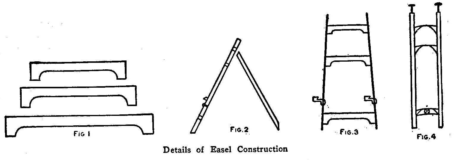
Details of Easel Construction
A strong and substantial easel may be made at home with very
little expense and no great difficulty.
Smooth down with a plane, four pieces of pine, 1 in. thick, 4 in.
wide and 4 ft. long, until suitable for legs. Make three
cross-pieces, Fig. 1, and join the legs with them as shown in
Fig. 2. With an auger bore a hole in each leg about 3 in. from
the bottom, and fit into each a little peg, Fig. 2, for the
picture to rest on. The peg should be of hardwood so it will not
break.
Cut the handle from an old broom, measure off the right length,
and put a hinge on one end. Fasten this leg on the second
cross-piece, thus forming a support for the two front legs, Fig.
3. The easel may be finished according to the individual taste.
It may be sandpapered and stained and varnished, or painted in
some pretty tint, or, if preferred, may be enameled.
Contributed by G. J. Tress.
How to Make a Wind Propeller
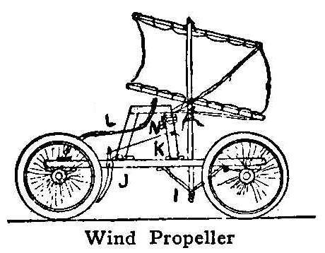
Wind Propeller
A wind propeller may be constructed with four old bicycle wheels
arranged with shafts pretty much like the shafts of a
hand-propelled cart. The platform is flatter, however, and the
body one tier so that it is lower. A framework of wood is built
at M and this is a support for several purposes. The sail is
secured to the mast which is fixed into the body of the cart as
shown. The sail is linen fabric. There are two crosspieces to aid
in keeping the sail properly opened. The steering arrangement is
through the rear shaft. The shaft is pivoted as in a
hand-propelled cart, and the rod I extends from the middle
connection of the shaft up to a point where the person seated on
the wooden frame can handle it. There is a brake arranged by
making a looped piece J and hinging it as shown. This piece is
metal, fitted with a leather face. The cord K is pulled to press
the brake. I marks the support for the mast underneath the body
of the cart. In a steady breeze this cart spins nicely along the
roads.
Replacing Ball Bearings
Never change a single ball in a bearing. Renew them all.
How to Construct an Annunciator
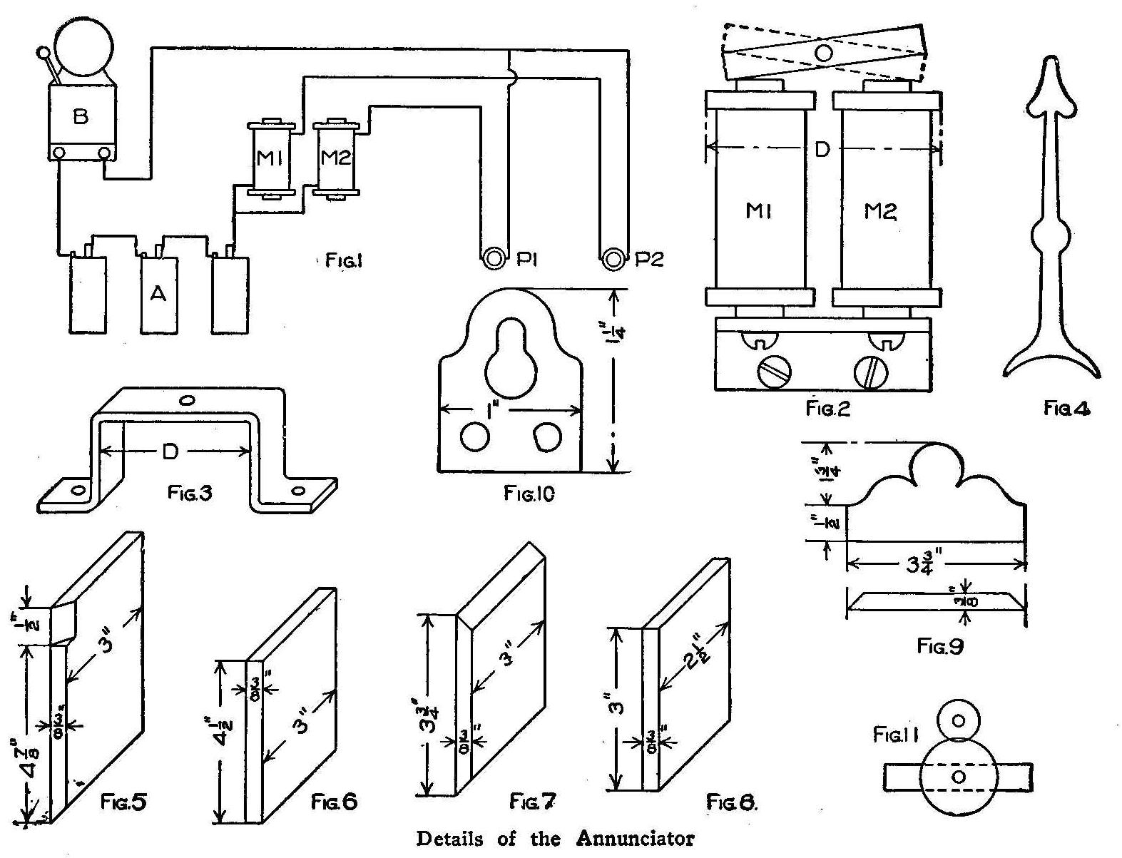
Details of the Annunciator
Oftentimes a single electric bell may be connected in a circuit
so that it can be operated from more than one push button. These
push buttons are usually located in entirely different parts of
the building and it is necessary to have some means of
determining the particular push button that was pressed and
caused the bell to operate. The electric annunciator is a device
that will indicate or record the various calls or signals that
may be sent over the circuits to which the annunciator is
connected. A very simple and inexpensive annunciator may be made
in the following way:
Before taking up the construction of the annunciator it would be
best to make a diagrammatic drawing of the circuit in which the
annunciator is to operate. The simplest circuit that will require
an annunciator is one where the bell may be operated from either
of two push buttons. In this case the annunciator must be
constructed to give only two indications. Fig. 1 shows how the
various’ elements of such a circuit may be connected. B is an
ordinary vibrating electric bell, M1 and M2 are the two
electromagnets of the annunciator, A is a battery of several dry
cells, and P1 and P2 are the push buttons from either of which
the bell may be operated.
When the push button P1 is pressed the circuit is completed
through the winding of the magnet M1 and its core becomes
magnetized. In a similar manner the core of the magnet M2 becomes
magnetized when the push button P2 is pressed and the circuit
completed through the winding of the magnet M2.
If an iron armature, that is supported by a shaft through its
center and properly balanced, be placed near the ends of the
cores of M1 and M2, as shown in Fig. 2, it may assume the
position indicated by either the full or dotted lines, depending
upon which of the magnets, M1 or M2, was last magnetized. The
position of this armature will serve to indicate the push button
from which the bell was operated. The magnets should be placed
inside a case and the indication may be made by a pointer
attached to the shaft, supporting the armature.
If you are able to secure the electromagnets from a discarded
electric bell they will work fine for the magnets M1 and M2. They
should be disconnected from their iron support and mounted upon
some non-magnetic material, such as brass or copper, making the
distance between their centers as small as possible. The piece of
metal upon which the magnets are mounted should now be fastened,
by means of two wood screws, to the back of the board, shown in
Fig. 6, that is to form the face of the annunciator. It should be
about 1/8 in. thick, 1/2 in. wide and long enough to extend a
short distance beyond the cores of the magnets M1 and M2. Drill a
1/16-in. hole through its center, as shown in Fig. 2. Drive a
piece of steel rod into this hole, making sure the rod will not
turn easily in the opening, and allow about 1/2 in. of the rod to
project on one side, and 1-1/2 in. on the other side.
Drill a hole in the board upon which the magnets are mounted so
that when the long end of the rod carrying the armature is passed
through the hole, the armature will be a little more than 1/16
in. from each magnet core. The short end of the rod should be
supported by means of a piece of strip brass bent into the form
shown in Fig. 3.
Drill a hole in the center of this piece, so the rod will pass
through it. When the armature has been put in its proper place,
fasten this strip to the board with two small wood screws. You
may experience some difficulty in locating the hole in the board
for the rod, and it no doubt would be best to drill this hole
first and fasten the magnets in place afterwards.
Two small collars should be fastened to the rod to prevent its
moving endwise. Fit the collars tightly on the rod to hold them
in place.
Cut the long end of the rod off so it projects through the face
of the annunciator about 3/8 in. Take some very thin sheet brass
and cut out a needle or indicator as shown in Fig. 4. In a small
piece of brass drill a hole so it will fit tight on the other end
of the rod. Solder the indicator to this piece and force it in
place on the end of the rod.
When the armature is the same distance from each core, the
indicator should be parallel to the long dimension of the face of
the case. The case of the instrument may be made in the following
way:
Secure a piece of 3/8-in. oak, or other hard wood, 3 in. wide and
2 ft. long. Then cut from this board the following pieces: two
whose dimensions correspond to those of Fig. 5 and are to form
the sides of the case; two whose dimensions correspond to those
of Fig. 6 and are to form the back and the face of the case;
three whose dimensions correspond to those of Figs. 7, 8, and 9
and are to form the lower and upper end of the case and the
finish for the top.
Secure a piece of window glass, 4-1/2 in. by 3-1/8 in. that is to
be used as the front. Before assembling the case cut on the inner
surface of the pieces forming the sides and the lower end, a
groove just wide enough to take the glass and 1/16 in. in depth.
The outer edge of this groove should be 3/8 in. from the outer
edge of the frame. After the case is fastened together there
should be a slot between the piece forming the upper end and the
piece that serves as a finish at the top, that will allow the
glass to be slipped into place. A small strip of wood should be
tacked over this slot, after the glass is put in place, to
prevent the dust and dirt from falling down inside of the case.
The piece upon which the works are to be mounted may be fastened
in place by means of four round-headed brass screws that pass
through the sides of the case. It should be fastened about 1/2
in. back of the glass front. The back may be fastened inside of
the case in a similar manner.
Cut two pieces, from some sheet brass, whose dimensions
correspond to those of Fig. 10. These pieces are to be used in
supporting the case by means of some small screws. Fasten three
binding-posts, that are to form the terminals of the annunciator,
on the top of the upper end of the case. Mark one of these
binding-posts C and the other two Ll and L2. Connect one terminal
of each of the magnet windings to the post marked C and the other
terminal to the posts Ll and L2. You can finish the case in any
style you may desire. Often times it is desirable to have it
correspond to the finish of the woodwork of the room in which it
is to be placed. The distance the point of the indicator will
move through depends upon the distance between the cores of the
magnets and the distance of the armature from these cores. These
distances are often times such that the indications of the cell
are not very definite. If the armature is moved too far from the
cores there is not sufficient pull exerted by them when
magnetized, to cause the position of the armature’ to change.
Mount on the shaft carrying the armature a small gear wheel.
Arrange another smaller gear to engage this on and fasten the
indicator to the shaft of the smaller gear. Any movement now of
the armature shaft will result in a relative large movement of
the indicator shaft. Figure 11 shows the arrangement of the gears
just described.
How to Make a Steam Calliope
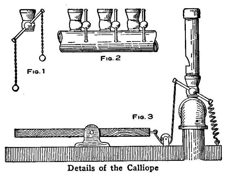
Details of the Calliope
Secure ten gas jet valves, the part of the gas fixture shown in
Fig. 1, and prepare to place them in a piece of 1-in. pipe, 12
in. long. This is done by drilling and tapping 10 holes, each 1
in. apart, in a straight line along the pipe. The valves screwed
into these holes appear as shown in Fig. 2. The whistles are made
from pipe of a diameter that will fit the valves. No dimensions
can be given for the exact lengths of these pipes as they must be
tried out to get the tone. Cut ten pieces of this pipe, each one
of a different length, similar to the pipes on a pipe organ. Cut
a thread on both ends, put a cap on the end intended for the top,
and fit a plug in the other end. The plug must have a small
portion of its side filed out, and a notch cut in the side of the
pipe with its horizontal edge level with the top of the plug.
This part of each whistle is made similar to making a bark
whistle on a green stick of willow. The pipes are then screwed
into the valves.
The whistles may be toned by trying out and cutting off pieces of
the pipe, or by filling the top end with a little melted lead.
The 1-in. pipe must have a cap screwed on one end and the other
attached to a steam pipe. The steam may be supplied by using an
old range boiler, placed horizontally in a fireplace made of
brick or sheet iron. If such a boiler is used, a small safety
valve should be attached. The keys and valve operation are shown
in Fig. 3. This is so plainly illustrated that it needs no
explanation.
Contributed by Herbert Hahn, Chicago.
Sharpening Scissors
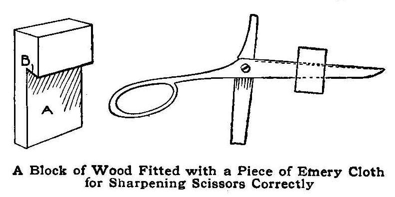
A Block of Wood Fitted with a Piece of Emery Cloth for Sharpening
Scissors Correctly
When sharpening scissors on a grindstone it is very difficult to
procure a straight edge. For those not having the facilities of a
grinding arrangement a very handy device that will produce a
straight and sharp edge can be easily constructed as follows:
Procure a block of wood, 1-1/2 in. long, 1 in. wide and 1/2 in.
thick, add saw a kerf square with the face of the block, as shown
at A. Attach a piece of fine emery cloth in the kerf, at B, with
glue, taking care to have it flat on the sloping surface only and
allowing no part of the cloth to turn the sharp corner and lie on
the back side. Apply the block to the scissor blade as shown and
draw it back and forth from one end to the other, being careful
to keep the back side of the blade flat against the block.
Without being familiar with scissors grinding, anyone can sharpen
them correctly with this block.
Contributed by Harriet Kerbaugh, Allentown, Pa.
Counter Brush for a Shop
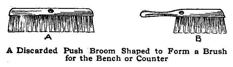
A Discarded Push Broom Shaped to Form a Brush for the Bench or Counter
A very serviceable brush for use around a shop can be made from a
discarded or worn-out push broom as shown at A. Pull out the
bristles from one-half of the brush and shape the wood of that
end with a knife or spokeshave to the form of a handle, and the
brush will be formed as shown at B.
Contributed by James T. Gaffney, Chicago.
A Curtain Roller
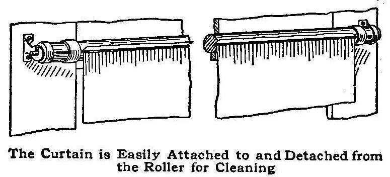
The Curtain is Easily Attached to and Detached from the Roller for Cleaning
Procure a window-shade roller, an umbrella rib and two strips of
oilcloth, each 1 in. wide and 4 in. long. Cut the roller off so
that it will be 6 in. longer than the distance across the window,
then cut a groove in it to insert the rib. Sew the pieces of
oilcloth so that they will just fit over the ends of the roller.
When this is done lay the curtain across the groove, then press
the rib and curtain into the groove and push the oilcloth bands
over the ends of the rib to keep it in place.
Contributed by E. L. McFarlane, Nashwaakees, N. B.
Shade-Holder Bracket for a Gas Jet
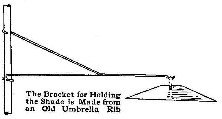
The Bracket for Holding the Shade is Made from an Old Umbrella Rib
An old umbrella rib makes a very effective shade-holder bracket
for a gas jet. The ends of the rib are bent to fit around the
pendant upright and the support end is shaped into a hook. It can
be quickly applied or removed. The outer end is bent into a hook
to hold the shade. The rib can be cut to fit a pendant arm of any
length.
Contributed by Edward Keegstra, Paterson, N. J.
To Longer Preserve Cut Flowers
A good way to keep cut flowers fresh is to place a small amount
of pure salt of sodium in the water. It is best to procure this
salt at a drug store because commercial salt will cause the
flowers to wither, due to the impurities in the soda. Call for
pure sodium chloride.
Glass Blowing and Forming
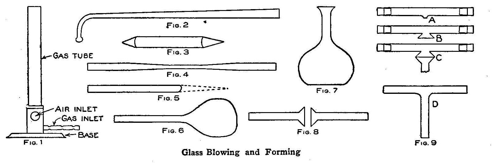
Glass Blowing and Forming
Fortunate indeed is the boy who receives a stock of glass tubing,
a Bunsen burner, a blowpipe, and some charcoal for a gift, for he
has a great deal of fun in store for himself. Glass blowing is a
useful art to understand, if the study of either chemistry or
physics is to be taken up, because much apparatus can be made at
home. And for itself alone, the forming of glass into various
shapes has not only a good deal of pleasure in it, but it trains
the hands and the eye.
Glass, ordinarily brittle and hard, becomes soft and pliable
under heat. When subjected to the action of a flame until dull
red, it bends as if made of putty; heated to a bright yellow, it
is so soft that it may be blown, pulled, pushed or worked into
any shape desired. Hence the necessity for a Bunsen burner, a
device preferred to all others for this work, because it gives
the hottest flame without soot or dirt. The Bunsen burner, as
shown in Fig. 1, is attached to any gas bracket with a rubber
tube, but the flame is blue, instead of yellow, as the burner
introduces air at its base, which mixes with the gas and so
produces an almost perfect combustion, instead of the partial
combustion which results in the ordinary yellow flame. All gas
stoves have Bunsen burners, and many oil stoves.
If gas is not available, an alcohol lamp with a large wick will
do almost as well. The blowpipe, shown in Fig. 2, is merely a
tube of brass with the smaller end at right angles to the pipe,
and a fine tip to reduce the size of the blast, which is used to
direct a small flame. Besides these tools, the glass worker will
need some round sticks of charcoal, sharpened like a pencil, as
shown in Fig. 3, a file, and several lengths of German glass
tubing.
To bend a length of the tubing, let it be assumed for the purpose
of making a syphon, it is only necessary to cork one end of the
tube and heat it near the top of the Bunsen flame, turning the
tubing constantly to make it heat evenly on all sides, until it
is a dull red in color. It will then bend of its own weight if
held in one hand, but to allow it to do so is to make a flat
place in the bend. The heating should be continued until the red
color is quite bright, when the open end of the tube is put in
the mouth and a little pressure of air made in the tube by
blowing. At the same time, the tube is bent, steadily but gently.
The compressed air in the tube prevents it from collapsing during
the process.
To make a bulb on the end of a tube, one end must be closed. This
is easily done by heating as before, and then pulling the tube
apart as shown in Fig. 4. The hot glass will draw, just like a
piece of taffy, each end tapering to a point. This point on one
length is successively heated and pressed toward and into the
tube, by means of a piece of charcoal, until the end is not only
closed, but as thick as the rest of the tube, as in Fig. 5. An
inch or more is now heated white hot, the tube being turned
continually to assure even heating and to prevent the hot end
from bending down by its own weight. When very hot, a sudden puff
into the open end of the tube will expand the hot glass into a
bulb, as in Fig. 6. These can be made of considerable size, and,
if not too thin, make very good flasks (Fig. 7) for physical
experiments. The base of the bulb should be flattened by setting
it, still hot, on a flat piece of charcoal, so that it will stand
alone.
To weld two lengths of, glass tubing together, heat the end of a
tube and insert the point of a piece of charcoal in the opening,
and twirl it about until the end of the tube has a considerable
flare. Do the same to the end of the other tube, which is to be
joined to the first, and then, heating both to a dull red, let
them touch and press lightly together as in Fig. 8. As soon as
they are well in contact, heat the two joined flares together,
very hot, and, pulling slightly, the flares will flatten out and
the tube be perfectly joined. Tubes joined without previous
flaring have a constricted diameter at the joint.
To make a T-joint in two pieces of tubing, it is necessary to
make a hole in the side of one piece, as shown at A in Fig. 9.
This is accomplished by the aid of the principle of physics that
gases expand when heated. Both ends of the tube, which should be
cold, are corked tightly. The whole is then gradually warmed by
being held near the flame. When warm, a small flame is directed
by the blowpipe from the Bunsen flame to a spot on one side of
the closed tube. As it heats, the air within the tube expands and
becomes compressed, and as soon as the hot spot on the side of
the tube is soft enough, the confined air blows out, pushing the
hot glass aside as it does so, leaving a small puncture. This is
to be enlarged with pointed charcoal until it also flares as
shown at B. This flare is then connected to the flared end of a
straight tube, C, and the T-joint, D, is complete.
Using the blowpipe is not difficult. The lips and cheeks should
be puffed out with a mouthful of air, which is ample to blow a
flame while the lungs are being refilled. In this way, it is
possible to use the blowpipe steadily, and not intermittently, as
is necessary if the lungs alone are the “bellows.”
Small glass funnels, such as are used in many chemical
operations, are made by first forming a bulb, then puncturing the
bulb at the top, when hot, with a piece of charcoal, and
smoothing down or flaring the edges. Very small and fine glass
tubes, such as are used in experiments to demonstrate capillary
attraction, water or other liquid rising in them when they are
plunged into it, are made by heating as long a section of tubing
as can be handled in the flame—2 in. will be found enough—and,
when very hot, giving the ends a sudden vigorous pull apart. The
tube pulls out and gets smaller and smaller as it does so, until
at last it breaks. But the fine thread of glass so made is really
a tube, and not a rod, as might be supposed. This can be
demonstrated by blowing through it at a gas flame, or by immersing
it in colored liquid. The solution will be seen to rise some
distance within the tube, the amount depending on the diameter of
the tube.
The file is for cutting the glass tubing into lengths convenient
to handle. It should be a three-cornered file, of medium
fineness, and is used simply to nick the glass at the place it is
desired to cut it. The two thumbs are then placed beneath the
tube, one on each side of the nick, and the tube bent, as if it
were plastic, at the same time pulling the hands apart. The tube
will break off squarely at the nick, without difficulty.
The entire outfit may be purchased from any dealer in chemical or
physical apparatus, or any druggist will order it. Enough tubing
to last many days, the Bunsen burner, blowpipe, file and charcoal
should not exceed $2 in cost.
Cadmium and Solder
The addition of cadmium
to soft solder composed of tin and lead,
lowers its melting point and increases its strength.
Telegraph Codes
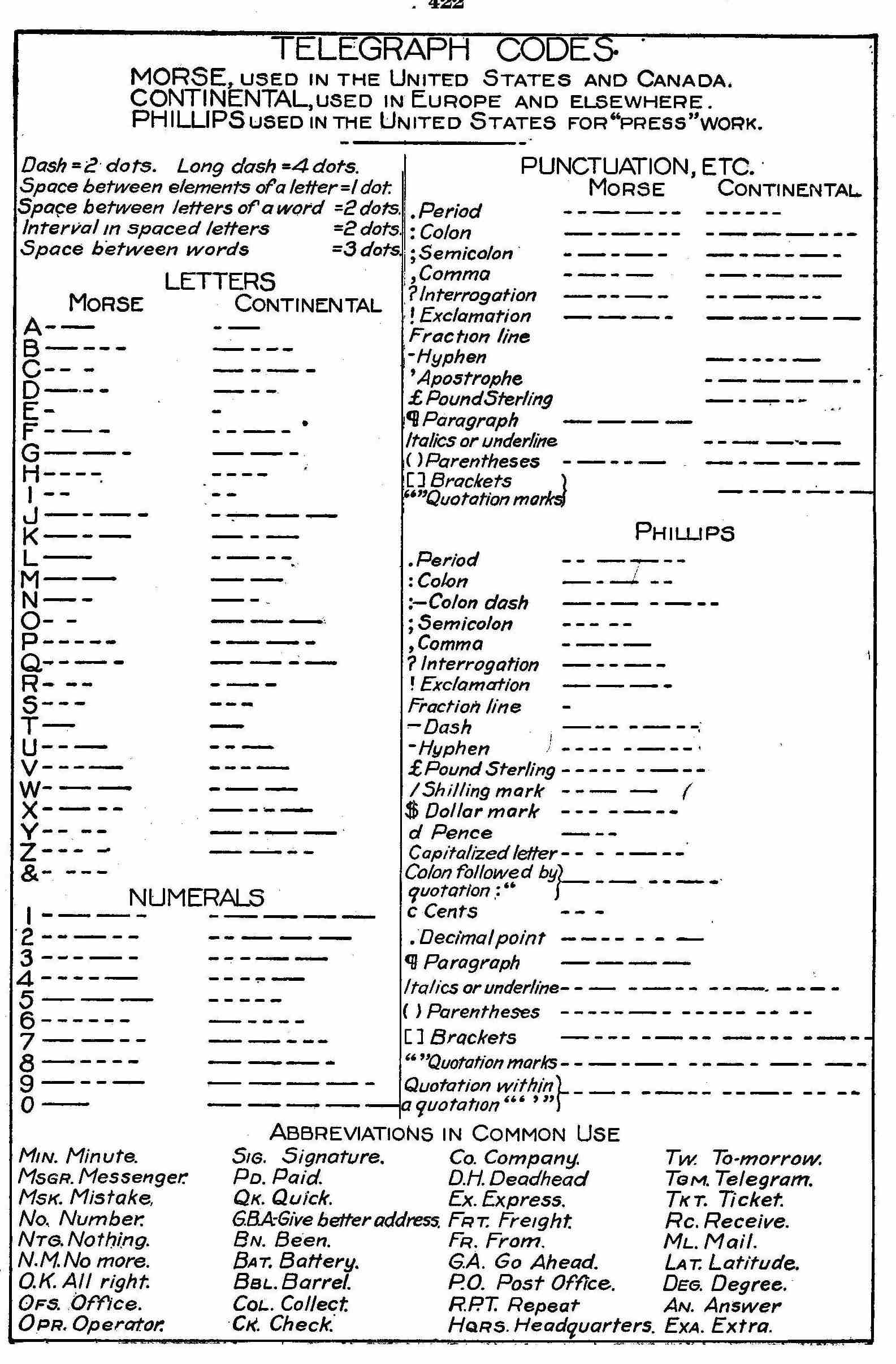
How to Make a Cruising Catamaran
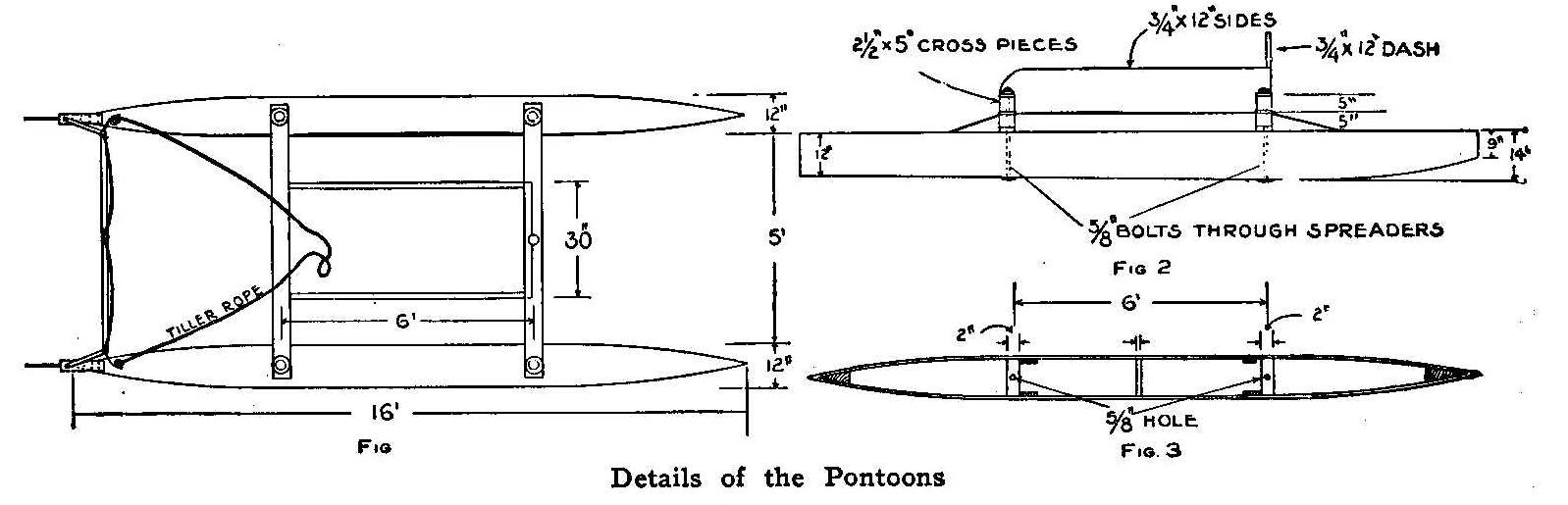
Details of the Pontoons
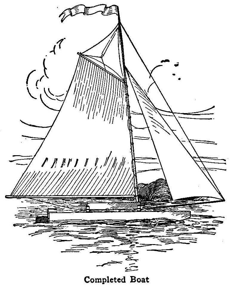
Completed Boat
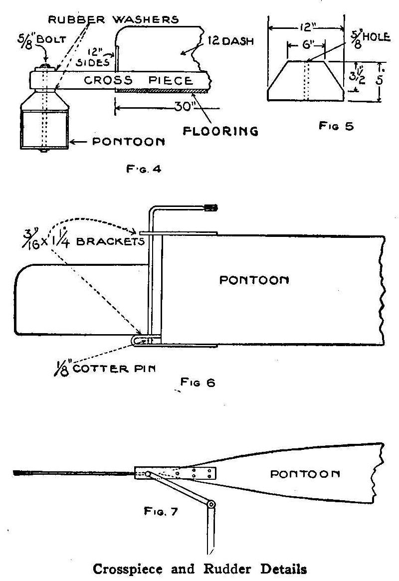
Crosspiece and Rudder Details
A launch is much safer than a sailing boat, yet there is not the
real sport to be derived from it as in sailing. Herein is given a
description of a sailing catamaran especially adapted for those
who desire to sail and have a safe craft. The main part of the
craft is made from two boats or pontoons with watertight tops,
bottoms and sides and fixed at a certain distance apart with a
platform on top for the passengers. Such a craft cannot be
capsized easily, and, as the pontoons are watertight, it will
weather almost any rough water. If the craft is intended for
rough waters, care must be taken to make the platform pliable yet
stiff and as narrow as convenient to take care of the rocking
movements.
This catamaran has been designed to simplify the construction,
and, if a larger size than the dimensions shown in Fig. 1 is
desired, the pontoons may be made longer by using two boards end
to end and putting battens on the inside over the joint. Each
pontoon is made of two boards 1 in. thick, 14 in. wide and 16 ft.
long, dressed and cut to the shape shown in Fig. 2. Spreaders are
cut from 2-in. planks, 10 in. wide and 12 in. long, and placed 6
ft. apart between the board sides and fastened with screws. White
lead should be put in the joints before turning in the screws.
Cut the ends of the boards so they will fit perfectly and make
pointed ends to the pontoons as shown in Fig. 3, and fit in a
wedge shaped piece; white lead the joints and fasten well with
screws.
Turn this shell upside down and lay a board 1/2 in. thick, 12 in.
wide and 16 ft. long on the edges of the sides, mark on the under
side the outside line of the shell and cut to shape roughly. See
that the spreaders and sides fit true all over, then put white
lead on the joint and nail with 1-3/4-in. finishing nails as
close as possible without weakening the wood. Slightly stagger
the nails in the sides, the 1-in. side boards will allow for
this, trim off the sides, turn the box over and paint the joints
and ends of the spreaders, giving them two or three coats and let
them dry.
Try each compartment for leaks by turning water in them one at a
time. Bore a 5/8-in. hole through each spreader in the center and
through the bottom board as shown. The top board, which is
1/4-in. thick, 12 in. wide and 16 ft. long, is put on the same as
the bottom.
After finishing both pontoons in this way place them parallel. A
block of wood is fastened on top of each pontoon and exactly over
each spreader on which to bolt the crosspieces as shown in Fig.
4. Each block is cut to the shape and with the dimensions shown
in Fig. 5.
The crosspieces are made from hickory or ash and each piece is
2-1/2 in. thick, 5 in. wide and 6-1/2 ft. long. Bore a 5/8-in.
hole 3 in. from each end through the 5-in. way of the wood. Take
maple flooring 3/4 in. thick, 6 in. wide, 74-1/2 in. long and
fasten with large screws and washers to the crosspieces and put
battens across every 18 in. Turn the flooring and crosspieces
upside down and fasten to the pontoons with long 5/8-in. bolts
put through the spreaders. Put a washer on the head of each bolt
and run them through from the under side. Place a thick rubber
washer under and on top of each crosspiece at the ends as shown
in Fig. 4. This will make a rigid yet flexible joint for rough
waters. The flooring being placed on the under side of the
crosspieces makes it possible to get the sail boom very low. The
sides put on and well fastened will greatly assist in stiffening
the platform and help it to stand the racking strains. These
sides will also keep the water and spray out and much more so if
a 12-in. dash is put on in front on top of the crosspiece.
The rudders are made as shown in Fig. 6, by using an iron rod 5/8
in. in diameter and 2 ft. long for the bearing of each. This rod
is split with a hacksaw for 7 in. of its length and a sheet metal
plate 3/32 in. thick, 6 in. wide, and 12 in. long inserted and
riveted in the split. This will allow 3/4 in. of the iron rod to
project from the bottom edge of the metal through which a hole is
drilled for a cotter pin. The bottom bracket is made from stake
iron bent in the shape of a U as shown, the rudder bearing
passing through a hole drilled in the upper leg and resting on
the lower. Slip the top bracket on and then bend the top end of
the bearing rod at an angle as shown in both Figs. 6 and 7.
Connect the two bent ends with a crosspiece which has a hole
drilled in its center to fasten a rope as shown in Fig. 1.
Attach the mast to the front crosspiece, also bowsprit, bracing
them both to the pontoons. A set of sails having about 300 sq.
ft. of area will be about right for racing. Two sails, main and
fore, of about 175 to 200 sq. ft. will be sufficient for
cruising.
Contributed by J. Appleton, Des Moines, Iowa.
Alligator Photo Mounts
Rough alligator finished photograph mounts will not receive a
good impression from a die. If a carbon paper is placed on the
mounts before making the impression, a good clear imprint will be
the result.
How to Attach a Sail to a Bicycle
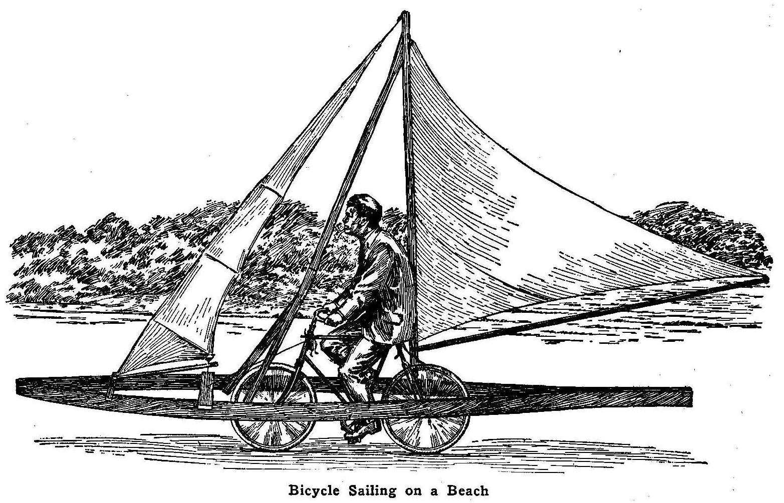
Bicycle Sailing on a Beach
This attachment was constructed for use on a bicycle to be ridden
on the well packed sands of a beach, but it could be used on a
smooth, level road as well. The illustration shows the main frame
to consist of two boards, each about 16 ft. long, bent in the
shape of a boat, to give plenty of room for turning the front
wheel. On this main frame is built up a triangular mast, to carry
the mainsail and jib, having a combined area of about 40 sq. ft.
The frame is fastened to the bicycle by numerous pieces of rope.
Sailing on a bicycle is very much different from sailing in a
boat, for the bicycle leans up against the wind, instead of
heeling over with it as the boat. It takes some time to learn the
supporting power of the wind, and the angle at which one must
ride makes it appear that a fall is almost sure to result. A turn
must be made by turning out of the wind, instead of, as in
ordinary sailing, into it; the boom supporting the bottom of the
mainsail is then swung over to the opposite tack, when one is
traveling at a good speed.
Removing Iodine Stains
A good way to chemically remove iodine stains from the hands or
linen is to wash the stains in a strong solution of hypo sulphite
of sodium, known as “hypo,” which is procurable at any
photographic-supply dealer’s or drug store. There is no danger of
using too strong a solution, but the best results are obtained
with a mixture of 1 oz. of hypo to 2 oz. of water.
Drying Photograph Prints without Curling
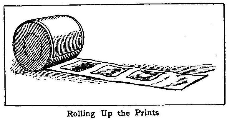
Rolling Up the Prints
Having made some photograph prints at one time that I wanted to
dry without the edges curling, I took an ordinary tin can and a
strip of clean cotton cloth, as wide as the can was long, and
wound it one turn around the can and then placed the prints, one
after the other, while they were damp, on the cloth, face
downward, and proceeded to roll the cloth and prints quite close
on the can. I then pinned the end of the cloth to keep it from
unwinding and set the whole in a draft for drying.
The curvature of the can just about counteracted the tendency of
the coating on the paper to make the prints curl and when they
were thoroughly dried and removed they remained nice and flat.
Contributed by W. H. Eppens, Chicago.
Puncturing Glass Plates
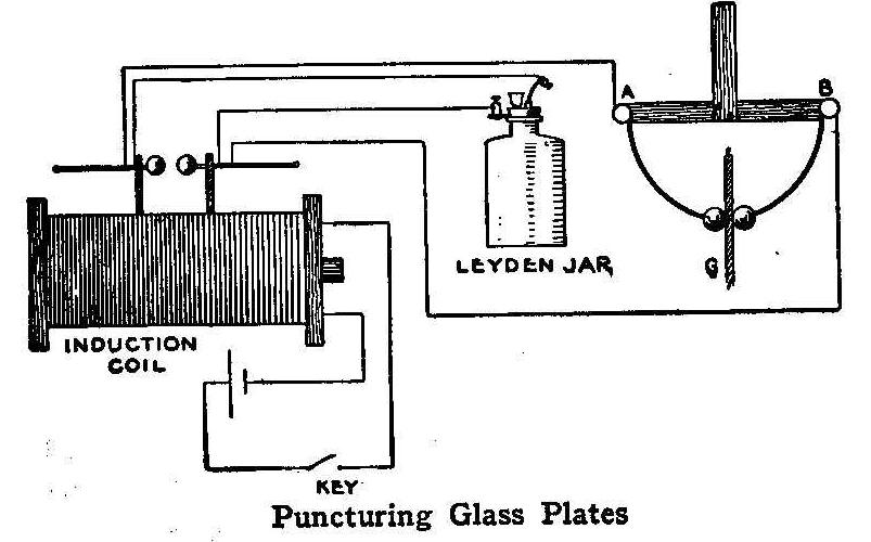
Puncturing Glass Plates
Anyone possessing a 1-in. induction coil and a 1-qt. Leyden jar
can easily perform the interesting experiment of piercing glass
plates. Connect the Leyden jar to the induction coil as shown in
the diagram. A discharger is now constructed of very dry wood and
boiled in paraffine for about 15 minutes. The main part of the
discharger, A B, is a piece of wood about 6 in. long and to the
middle of it is fastened a wood handle by means of one or two
wood screws. A binding-post is fastened to each end of the main
piece or at A and B as shown in the diagram. Two stiff brass
wires of No. 14 gauge and 6 in. long, with a small brass ball
attached to one end of each, are bent in an arc of a circle and
attached one to each binding-post.
A plate of glass, G, is now placed between the two brass balls
and the coil set in action. The plate will soon be pierced by the
spark. Larger coils will pierce heavier glass plates.
Contributed by I. Wolff, Brooklyn, N. Y.
A Home-Made Still
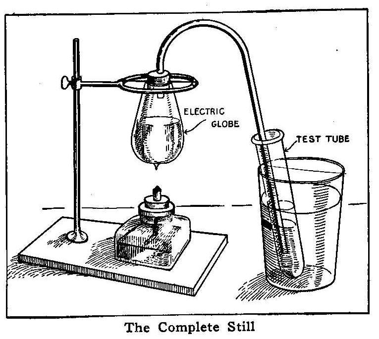
The Complete Still
Remove the metal end of an old electric light globe. This can be
done by soaking a piece of twine in alcohol and tying it around
the globe at the place the break is to be made. Light the string
and after it is burned off, turn cold water on the globe. The
result will be a smooth break where the string was placed.
Purchase a piece of glass tubing from your druggist and secure a
cork that will fit the opening in the glass bulb. Bore a hole in
the cork the right size for the glass tube to fit in tightly. If
you cannot get a glass tube with a bend in it, you will have to
make a bend, as shown in the illustration, by heating the tube at
the right place over an alcohol lamp and allowing the weight of
the glass to make the bend while it is hot.
Insert the short end of the tube in the cork and place the other
end in a test tube that is placed in water as shown. The globe
may be fastened in position by a wire passed through the cork and
tied to a ring stand. If you do not have a ring stand, suspend
the globe by a wire from a hook that is screwed into any
convenient place.
A neat alcohol lamp may be made of an old ink or muscilage
bottle. Insert a wick in a piece of the glass tubing and put this
through a hole bored in a cork and the lamp is ready to burn
alcohol or kerosene. Alcohol is cleaner to use as a fuel. Fill
the globe about two-thirds full of water or other liquid and
apply the heat below as shown. The distilled liquid will collect
in the test tube.
Contributed by Clarence D. Luther, Ironwood, Mich.
Old-Time Magic
Balancing Forks on a Pin Head
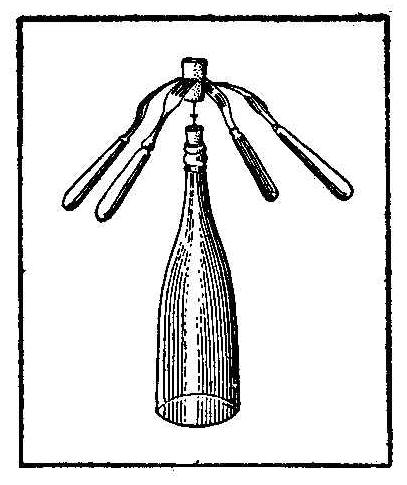
Two, three and four common table forks can be made to balance on
a pin head as follows: Procure an empty bottle and insert a cork
in the neck. Stick a pin in the center of this cork so that the
end will be about 1-1/2 in. above the tap. Procure another cork
about 1 in. in diameter by 1-3/4 in. long. The forks are now
stuck into the latter cork at equal distances apart, each having
the same angle from the cork. A long needle with a good sharp
point is run through the cork with the forks and 1/2 in. of the
needle end allowed to project through the lower end.
The point of the needle now may be placed on the pin head. The
forks will balance and if given a slight push they will appear to
dance. Different angles of the forks will produce various feats
of balancing.
Contributed by O. E. Tronnes, Wilmette, Ill.
The Buttoned Cord
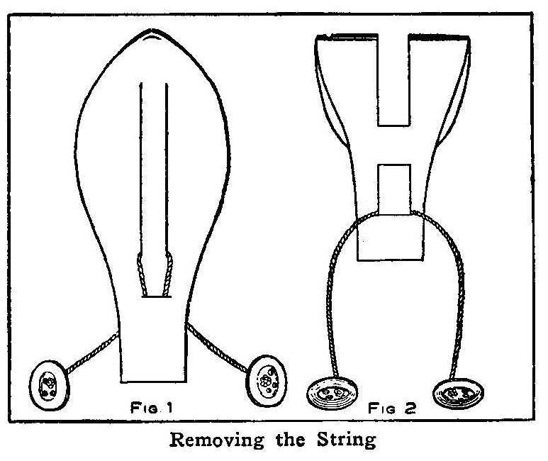
Removing the String
Cut a piece of heavy paper in the shape shown in Fig. 1 and make
two cuts down the center and a slit as long as the two cuts are
wide at a point about 1 in. below them. A string is put through
the slit, the long cuts and back through the slit and then a
button is fastened to each end. The small slit should not be so
large as the buttons. The trick is to remove the string. The
solution is quite simple. Fold the paper in the middle and the
part between the long cuts will form a loop. Bend this loop down
and pass it through the small slit. Turn the paper around and it
will appear as shown in Fig. 2. One of the buttons may now be
drawn through and the paper restored to its original shape.
Experiment with an Incandescent Lamp
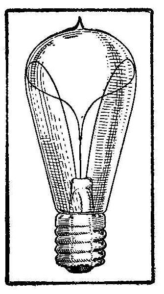
When rubbing briskly an ordinary incandescent lamp on a piece of
cloth and at the same time slightly revolving it, a luminous
effect is produced similar to an X-ray tube. The room must be
dark and the lamp perfectly dry to obtain good results. It
appears that the inner surface of the globe becomes charged,
probably by induction, and will sometimes hold the filament as
shown in the sketch.
Contributed by E. W. Davis, Chicago.
How to Make a Small Motor
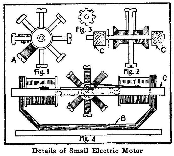
Details of Small Electric Motor
The accompanying sketch shows how to make a small motor to run on
a battery of three or four dry cells and with sufficient power to
run mechanical toys. The armature is constructed, as shown in
Figs. 1 and 2, by using a common spool with 8 flat-headed screws
placed at equal distances apart and in the middle of the spool.
Each screw is wound with No. 24 gauge iron wire, as shown at A,
Fig. 1. The commutator is made from a thin piece of copper, 1 in.
in diameter and cut as shown in Fig. 3, leaving 8 points, 1/8 in.
wide and 1/8 in. deep. The field is built up by using 8 strips
of tin, 12 in. long and 2 in. wide, riveted together and shaped
as shown at B, Fig. 4. Field magnets are constructed by using two
3/8-in. bolts, 1-1/2 in. long. A circular piece of cardboard is
placed on each end of the bolt, leaving space enough for the bolt
to pass through the field B, and to receive a nut. Wind the
remaining space between the cardboards with 30 ft. of No. 22
double-wound cotton-covered copper wire. A light frame of wood
is built around the magnets, as shown at C, Fig. 4. Holes are
made in this frame to receive the axle of the armature. Two
strips of copper, 1/4 in. wide and 3 in. long, are used for the
brushes. The armature is placed in position in its bearings and
the brushes adjusted as shown in Fig. 4, one brush touching the
shaft of the armature outside of the frame, and the other just
touching the points of the commutator, which is placed on the
shaft inside of the frame. Connect the outside wire of one magnet
to the inside wire of the other, and the remaining ends, one to
the batteries and back to the brush that touches the shaft, while
the other is attached to the brush touching the commutator. In
making the frame for the armature bearings, care should be taken
to get the holes for the shaft centered, and to see that the
screws in the armature pass each bolt in the magnets at equal
distances, which should be about 1/8 in.
Aluminum Polish
An emulsion of equal parts of rum and olive oil can be used for
cleaning aluminum, says Blacksmith and Wheelwright.
Potash lye,
not too strong, is also effective in brightening aluminum, and
benzol can be used for the same purpose. A good polish for
aluminum consists of a paste formed of emery and tallow, the
finish luster being obtained by the use of rouge powder and oil
of turpentine.
Homemade Blowpipe

A Pipe Blowpipe
Procure a clay pipe, a cork and a small glass or metal tube drawn
to a small opening in one end. Make a hole in the cork just large
enough to permit the tube to pass through tightly so no air can
pass out except through the hole in the tube. Put the tube in the
hole with the small opening at the top or projecting end. Push
the cork into the bowl of the pipe and the blowpipe is ready for
use.
Contributed by Wilbur Cryderman, Walkerton, Onto
Substitute Sink or Bathtub Stopper
Milk-bottle caps make good substitutes for the regular rubber
stoppers in sinks and bathtubs. The water soon destroys them, but
as a new one usually is had each day, they can be used until a
regular stopper is obtained. A good permanent stopper can be made
by cutting a hollow rubber return ball in half, using one part
with the concave side up. It will fit the hole of any sink or
bathtub. One ball thus makes two stoppers at a cost of about 5
cents.
Safety Tips on Chair Rockers
Some rocking chairs are so constructed that when the person
occupying it gives a hard tilt backward, the chair tips over or
dangerously near it. A rubber-tipped screw turned into the under
side of each rocker, near the rear end, will prevent the chair
from tipping too far back.
How to Make a Toy Flier
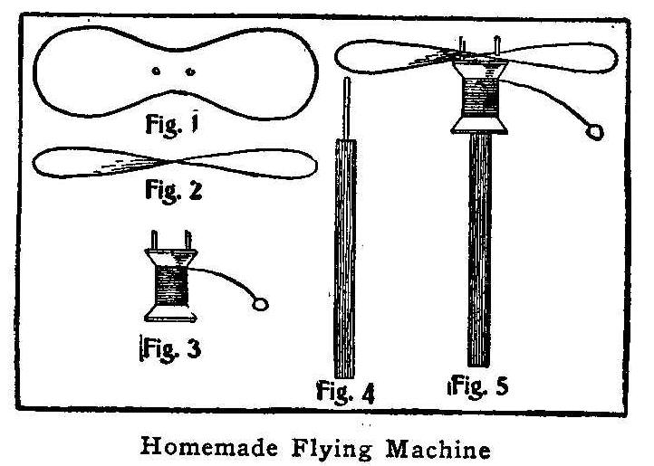
Homemade Flying Machine
While a great many people are looking forward to the time when we
shall successfully travel through the air, we all may study the
problem of aerial navigation by constructing for ourselves a
small flying machine as illustrated in this article.
A wing is made in the shape shown in Fig. 1 by cutting it from
the large piece of an old tin can, after melting the solder and
removing the ends. This wing is then given a twist so that one
end will be just opposite the other and appear as shown in Fig.
2. Secure a common spool and drive two nails in one end, leaving
at least 1/2 in. of each nail projecting after the head has been
removed. Two holes are made in the wing, exactly central, to fit
on these two nails. Another nail is driven part way into the end
of a stick, Fig. 4, and the remaining part is cut off so the
length will be that of the spool. A string is used around the
spool in the same manner as on a top. The wing is placed on the
two nails in the spool, and the spool placed on the nail in the
stick, Fig. 5, and the flier is ready for action. A quick pull on
the string will cause the wing to leave the nails and soar upward
for a hundred feet or more. After a little experience in twisting
the wing the operator will learn the proper shape to get the best
results.
Be very careful in making the tests before the wings are turned
to the proper shape, as the direction of the flier cannot be
controlled and some one might be injured by its flight.
How to Make an Ironing-Board Stand
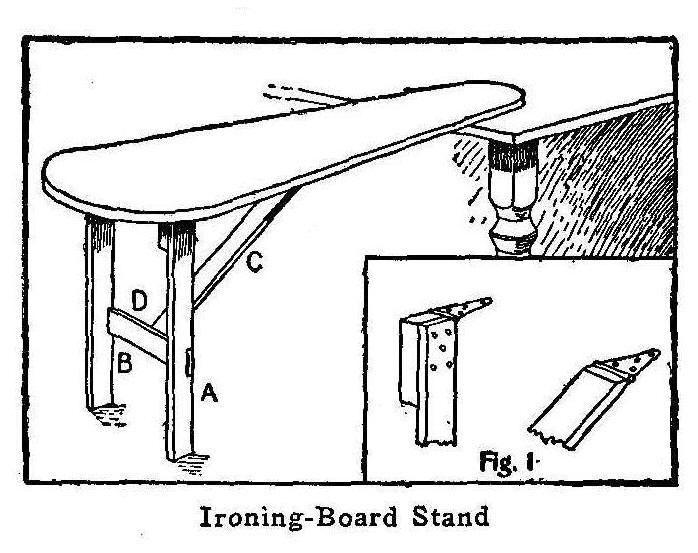
Ironing-Board Stand
Secure some 1 by 3-in. boards, about 3 ft. long, and plane them
smooth. Cut the two pieces A and B 30 in. long and make a notch
in each of them, about one-third of the way from one end, 1 in.
deep and 3 in. long. These notches are to receive the piece D,
which has a small block fastened to its side to receive the end
of the brace C. The brace C is 36 in. long. The upper ends of the
pieces A, B and C are fastened to a common ironing board by using
iron hinges as shown in Fig. 1. As the piece D is fitted loosely,
it may be removed and the brace, C, with the legs, A and B,
folded up against the board.
Contributed by Bert Kottinger, San Jose, Cal.
A Home-Made Electric Plug
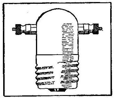
A plug suitable for electric light extension or to be used in
experimenting may be made from an old electric globe. The glass
is removed with all the old composition in the brass receptacle,
leaving only the wires. On the ends of the wires, attach two
small binding posts. Fill the brass with plaster of paris, and in
doing this keep the wires separate and the binding-posts opposite
each other. Allow the plaster to project about 3/4 in. above the
brass, to hold the binding-posts as shown.
Contributed by Albert E. Welch, New York.
How to Make an Electric Fire Alarm
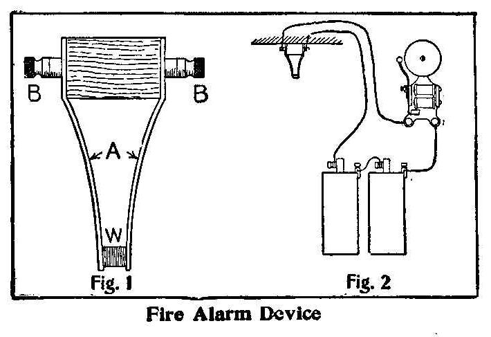
Fire Alarm Device
On each end of a block of wood, 1 in. square and 1 in. long,
fasten a strip of brass 1/4 by 3 in., bent in the shape as shown
in the sketch at A, Fig; 1. These strips should have sufficient
bend to allow the points to press tightly together. A piece of
beeswax, W, is inserted between the points of the brass strips to
keep them apart and to form the insulation. A binding post, B, is
attached to each brass strip on the ends of the block of wood.
The device is fastened to the wall or ceiling, and wire
connections made to the batteries and bells as shown in the
diagram, Fig. 2. When the room becomes a little overheated the
wax will melt and cause the brass strips to spring together,
which will form the circuit and make the bell ring. Each room in
the house may be connected with one of these devices, and all on
one circuit with one bell.
Home-Made Boy’s Car
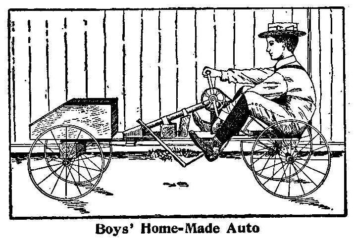
Boys’ Home-Made Auto
The accompanying cut shows how a boy may construct his own auto
car. The car consists of parts used from a boy’s wagon and some
old bicycle parts. The propelling device is made by using the
hanger, with all its parts, from a bicycle. A part of the bicycle
frame is left attached to the hanger and is fastened to the main
board of the car by blocks of wood as shown. The chain of a
bicycle is used to connect the crank hanger sprocket to a small
sprocket fastened in the middle of the rear axle of the car. The
front axle is fastened to a square block of wood, which is
pivoted to the main board. Ropes are attached to the front axle
and to the back part of the main board to be used with the feet
in steering the car. To propel the auto, turn the cranks by
taking hold of the bicycle pedals.
Contributed by Anders Neilsen, Oakland, Cal.
Photographs in Relief Easily Made
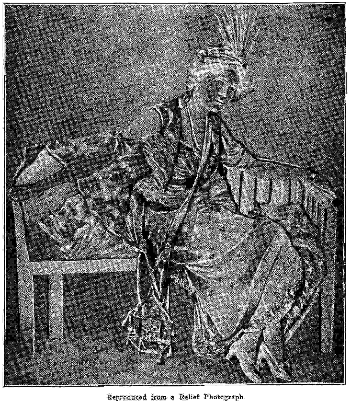
Reproduced from a Relief Photograph
Relief photographs, although apparently difficult to produce, can
be made by any amateur photographer. The negative is made in the
usual way and, when ready for printing, a positive or
transparency is made from it in the same manner as a lantern
slide or window transparency, says the Sketch, London. Use the
same size plate as the negative for the transparency. To make the
print in relief place the positive in the frame first with the
film side out and the negative on top of this with the film side
up in the usual manner. Put in the paper and print. This will
require a greater length of time than with the ordinary negative
on account of printing through double glass and films. In using
printing-out papers care should be taken to place the printing
frame in the same position and angle after each examination.
Wireless Tip
Place the transmitting instruments of a wireless outfit as close
together as possible.
How to Make a Wireless Telephone
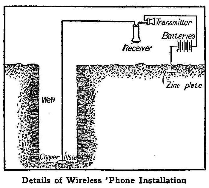
Details of Wireless Phone Installation
A noted French scientist, Bourbouze, was able to keep up
communication with the outside during the siege of Paris by
making practical application of the earth currents. The distance
covered is said to have been about 30 miles. Another scientist
was able to telephone through the earth without the aid of wires.
Nothing, however, has been made public as to how this was
accomplished.
It is my object to unveil the mystery and to render this field
accessible to others, at least to a certain degree, for I have by
no means completed my researches in this particular work.
In order to establish a wireless communication between two points
we need first of all a hole or well in the ground at each point.
In my experiments I was unable to get a deep well, but the
instruments worked fine for a distance of 200 ft., using wells
about 25 ft. deep. As in ordinary telephone lines, we require a
transmitter and receiver at each point. These must be of the
long-distance type. If a hole is dug or a well is found suitable
for the purpose, a copper wire is hung in the opening, allowing
the end to touch the bottom. To make the proper contact an oval
or round—but not pointed-copper plate is attached to the end of
the wire. If a well is used, it is necessary to have a waterproof
cable for the part running through the water. The top end is
attached to the telephone transmitter and receiver, as in the
ordinary telephone, to the batteries and to a zinc plate, which
is to be buried in the earth a few feet away from the well or
hole, and not more than 1 ft. under the surface. A battery of
four dry cells is used at each station.
Both stations are connected in the same way, as shown in the
sketch. This makes it possible for neighbors to use their wells
as a means of communication with each other.
Contributed by A. E. Joerin.
Eyelets for Belts
If eyelets, such as used in shoes, are put into the lace holes of
a belt, the belt will last much longer. The eyelets, which may be
taken from old shoes, will prevent the lace from tearing out. I
have used this method on several kinds of belts, always with
entire satisfaction.
Contributed by Irl R. Hicks.
How to Make a Life Buoy
Any boy may be able to make, for himself or friends, a life buoy
for emergency use in a rowboat or for learning to swim. Purchase
1-3/4 yd. of 30-in. canvas and cut two circular pieces, 30 in. in
diameter, also cutting a round hole in the center of them, 14 in.
in diameter. These two pieces are sewed together on the outer and
inner edges, leaving a space, about 12 in. in length, open on the
outer seam. Secure some of the cork used in packing Malaga grapes
from a grocery or confectionery store and pack it into the pocket
formed between the seams through the hole left in the outer edge.
When packed full and tight sew up the remaining space in the
seam. Paint the outside surface and the seams well with white
paint to make it water-tight.
Contributed by Will Hare, Petrolea, Onto.
A Home-Made Microscope
A great many times we would like to examine a seed, an insect or
the fiber of a piece of wood but have no magnifier handy. A very
good microscope may be made out of the bulb of a broken
thermometer. Empty out the mercury,
which is easily done by
holding the bulb with the stem down over a lamp or candle. A
spirit lamp is the best, as it makes no smoke and gives a steady
heat. Warm the bulb slowly and the
mercury will be expelled and
may be caught in a tea cup. Do not heat too fast, or the pressure
of the mercury
vapor may burst the glass bulb, cautions the
Woodworkers’ Review. To fill the bulb with water warm it and
immerse the end of the tube in the water. Then allow it to cool
and the pressure of the air will force the water into the bulb.
Then boil the water gently, holding the bulb with the stem up;
this will drive out all the air, and by turning the stem or tube
down and placing the end in water the bulb will be completely
filled. It is surprising how much can be seen by means of such a
simple apparatus.
A Novel Electric Time Alarm
Electric Time Alarm
All time alarms run by clockwork must be wound and set each time.
The accompanying diagram shows how to make the connection that
will ring a bell by electric current at the time set without
winding the alarm. The bell is removed from an ordinary alarm
clock and a small metal strip attached, as shown at B. An
insulated connection is fastened on the clapper of the bell, as
shown at A. The arm holding the clapper must be bent to have the
point A remain as close to the strip B as possible without
touching it. The connection to the battery is made as shown. When
the time set for the alarm comes the clapper will be moved far
enough to make the contact. In the course of a minute the catch
on the clapper arm will be released and the clapper will return
to its former place.
How to Make a Phonograph Record Cabinet
Phonograph Wax Record Case
The core, Fig. 1, consists of six strips of wood beveled so as to
form six equal sides. The strips are 3 ft. long and 3 in. wide on
the outside bevel and are nailed to three blocks made hexagon,
as shown in Fig. 2, from 7/8-in. material. One block is placed at
each end and one in the middle. A 1/2-in. metal pin is driven in
a hole bored in the center of each end block. The bottoms of the
pasteboard cases, used to hold the wax records, are either tacked
or glued to this hexagon core, as shown in Fig. 3, with their
open ends outward.
Two circular pieces are made of such a diameter as will cover the
width of the core and the cases attached, and extend about 1/2
in. each side. A 1/2-in. hole is bored in the center of these
pieces to receive the pins placed in the ends of the core, Fig.
1. These will form the ends of the cabinet, and when placed, one
on each end of the core, heavy building paper or sheet metal is
tacked around them for a covering, as shown in Fig. 4. A small
glass door is made, a little wider than one row of cases, and
fitted in one side of the covering. The outside may be painted or
decorated in any way to suit the builder.
Experiments with a Mirror
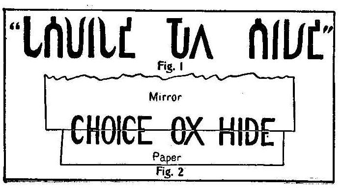
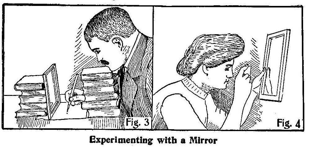
Experimenting with a Mirror
Ask your friend if he can decipher the sign as illustrated in the
sketch, Fig. 1, which you pretend to have read over the shop of
an Armenian shoemaker.
He will probably tell you that he is not conversant with Oriental
languages. He will not believe it if you tell him it is written
in good English, but place a frameless mirror perpendicularly
on the mysterious script, right across the quotation marks, and
it will appear as shown in Fig. 2. We understand at once that the
reflected image is the faithful copy of the written half.
With the aid of a few books arrange the mirror and the paper as
shown in Fig. 3 and ask your friend to write anything he chooses,
with the condition that he shall see his hand and read the script
in the mirror only. The writer will probably go no farther than
the first letter. His hand seems to be struck with paralysis and
unable to write anything but zigzags, says Scientific American.
Another experiment may be made by taking an egg shell and
trimming it with the scissors so as to reduce it to a half shell.
In the hollow bottom roughly draw with your pencil a cross with
pointed ends. Bore a hole, about the size of a pea, in the center
of the cross. Place yourself so as to face a window, the light
falling upon your face, not upon the mirror which you hold in one
hand. Close one eye. Place the shell between the other eye and
the mirror, at a distance of 2 or 3 in. from either, the
concavity facing the mirror as shown in Fig. 4. Through the hole
in the shell look at the mirror as if it were some distant
object. While you are so doing the concave shell will suddenly
assume a strongly convex appearance. To destroy the illusion it
becomes necessary either to open both eyes or to withdraw the
shell away from the mirror. The nearer the shell to the mirror
and the farther the eye from the shell the more readily comes the
illusion.
Miniature Electric Lamps
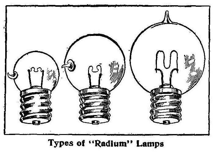
Types of “Radium” Lamps
After several years’ research there has been produced a miniature
electric bulb that is a great improvement and a decided departure
from the old kind which used a carbon filament. A metallic
filament prepared by a secret chemical process and suspended in
the bulb in an S-shape is used instead of the old straight span.
The voltage is gauged by the length of the span. The brilliancy
of the filament excels anything of its length in any voltage. Of
course, the filament is not made of the precious metal, radium;
that simply being the trade name. However, the filament is
composed of certain metals from which radium is extracted.
The advantages of the new bulb are manifold. It gives five times
the light on the same voltage and uses one-half of the current
consumed by the old carbon filament. One of the disadvantages of
the old style bulb was the glass tip, which made a shadow. This
has been obviated in the radium bulb by blowing the tip on the
side, as shown in the sketch, so as to produce no shadow.
How to Make a Magazine Clamp
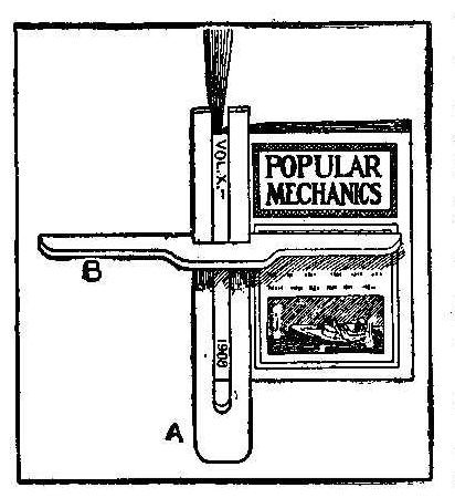
This device as shown in the illustration can be used to hold
newspapers and magazines while reading. Two pieces of wood are
cut as shown, one with a slot to fit over the back of a magazine
and the other notched to serve as a clamp. The piece, A, may be
slotted wide enough to insert two or three magazines and made
long enough to hold several newspapers.
Pewter Finish for Brass
A color resembling pewter may be given to brass by boiling the
castings in a cream of tartar solution containing a small amount
of chloride of tin.
Drowning a Dog’s Bark with Water
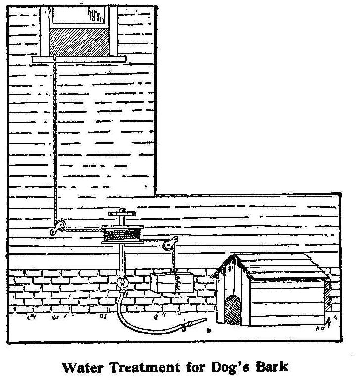
Water Treatment for Dog’s Bark
The owner of two dogs was very much annoyed by the dogs barking
at night. It began to be such a nuisance that the throwing of old
shoes and empty bottles did not stop the noise. The only thing
that seemed to put a stop to it was water. Being on the third
floor of the house, and a little too far from the kennel to throw
the water effectively, a mechanism was arranged as shown in the
sketch.
A faucet for the garden hose was directly below the window. An
8-in. wooden grooved pulley was slipped over an axle which had
one end fitted on the handle of the faucet. A rope was extended
to the window on the third floor and passed around the pulley
several times, thence over an iron pulley fastened to the wall of
the house and a weight was attached to its end. By pulling the
rope up at the window the large pulley would turn on the water
and when released the weight would shut off the flow. The nozzle
was fastened so as to direct the stream where it would do the
most good.
Contributed by A. S. Pennoyer, Berkeley, Cal.
Cost of Water
The average cost of supplying 1,000,000 gal. of water, based on
the report of twenty-two cities, is $92. This sum includes
operating expenses and interest on bonds.
How to Make a Wondergraph
By F. E. Tuck
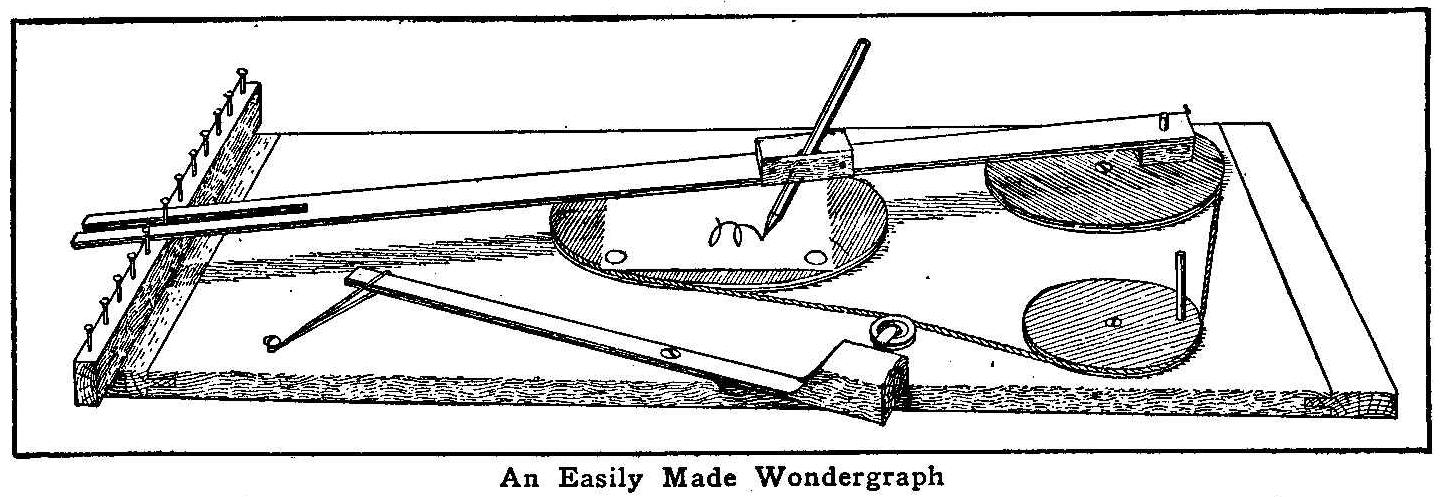
An Easily Made Wondergraph
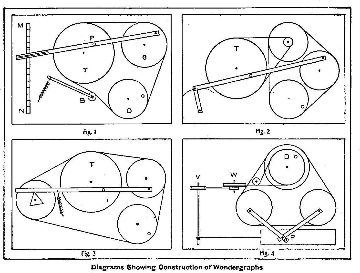
Diagrams Showing Construction of Wonder graphs
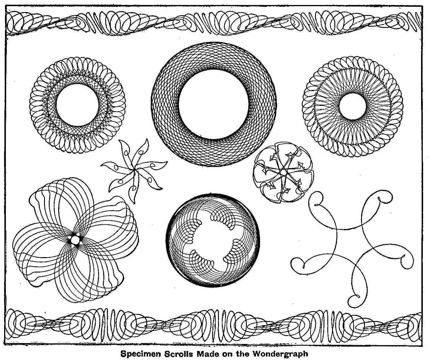
Specimen Scrolls Made on the Wondergraph
An exceedingly interesting machine is the so-called wondergraph.
It is easy and cheap to make and will furnish both entertainment
and instruction for young and old. It is a drawing machine, and
the variety of designs it will produce, all symmetrical and
ornamental and some wonderfully complicated, is almost without
limit. Fig. 1 represents diagrammatically the machine shown in
the sketch. This is the easiest to make and gives fully as great
a variety of results as any other.
To a piece of wide board or a discarded box bottom, three grooved
circular disks are fastened with screws so as to revolve freely
about the centers. They may be sawed from pieces of thin board
or, better still, three of the plaques so generally used in
burnt-. wood work may be bought for about 15 cents. Use the
largest one for the revolving table T. G is the guide wheel and
D the driver with attached handle. Secure a piece of a 36-in.
ruler, which can be obtained from any furniture dealer, and nail
a small block, about 1 in. thick, to one end and drill a hole
through both the ruler and the block, and pivot them by means of
a wooden peg to the face of the guide wheel. A fountain pen, or
pencil, is placed at P and held securely by rubber bands in a
grooved block attached to the ruler. A strip of wood, MN, is
fastened to one end of the board. This strip is made just high
enough to keep the ruler parallel with the face of the table, and
a row of small nails are driven part way into its upper edge.
Anyone of these nails may be used to hold the other end of the
ruler in position, as shown in the sketch. If the wheels are not
true, a belt tightener, B, may be attached and held against the
belt by a spring or rubber band.
After the apparatus is adjusted so it will run smoothly, fasten a
piece of drawing paper to the table with a couple of thumb tacks,
adjust the pen so that it rests lightly on the paper and turn the
drive wheel. The results will be surprising and delightful. The
accompanying designs were made with a very crude combination of
pulleys and belts, such as described.
The machine should have a speed that will cause the pen to move
over the paper at the same rate as in ordinary writing. The ink
should flow freely from the pen as it passes over the paper. A
very fine pen may be necessary to prevent the lines from running
together.
The dimensions of the wondergraph may vary. The larger designs in
the illustration were made on a table, 8 in. in diameter, which
was driven by a guide wheel, 6 in. in diameter. The size of the
driver has no effect on the form or dimensions of the design, but
a change in almost any other part of the machine has a marked
effect on the results obtained. If the penholder is made so that
it may be fastened at various positions along the ruler, and the
guide wheel has holes drilled through it at different distances
from the center to hold the peg attaching the ruler, these two
adjustments, together with the one for changing the other end of
the ruler by the rows of nails, will make a very great number of
combinations possible. Even a slight change will greatly modify a
figure or give an entirely new one. Designs may be changed by
simply twisting the belt, thus reversing the direction of the
table.
If an arm be fastened to the ruler at right angles to it,
containing three or four grooves to hold the pen, still different
figures will be obtained. A novel effect is made by fastening two
pens to this arm at the same time, one filled with red ink and
the other with black ink. The designs will be quite dissimilar
and may be one traced over the other or one within the other
according to the relative position of the pens.
Again change the size of the guide wheel and note the effect. If
the diameter of the table is a multiple of that of the guide
wheel, a complete figure of few lobes will result as shown by the
one design in the lower right hand corner of the illustration.
With a very flexible belt tightener an elliptical guide wheel may
be used. The axis may be taken at one of the foci or at the
intersection of the axis of the ellipse.
The most complicated adjustment is to mount the table on the face
of another disc, table and disc revolving in opposite directions.
It will go through a long series of changes without completing
any figure and then will repeat itself. The diameters may be made
to vary from the fraction of an inch to as large a diameter as
the size of the table permits. The designs given here were
originally traced on drawing paper 6 in. square.
Remarkable and complex as are the curves produced in this manner,
yet they are but the results obtained by combining simultaneously
two simple motions as may be shown in the following manner: Hold
the table stationary and the pen will trace an oval. But if the
guide wheel is secured in a fixed position and the table is
revolved a circle will be the result.
So much for the machine shown in Fig. 1. The number of the
modifications of this simple contrivance is limited only by the
ingenuity of the maker. Fig. 2 speaks for itself. One end of the
ruler is fastened in such a way as to have a to-and-fro motion
over the arc of a circle and the speed of the table is geared
down by the addition of another wheel with a small pulley
attached. This will give many new designs. In Fig. 3 the end of
the ruler is held by a rubber band against the edge of a thin
triangular piece of wood which is attached to the face of the
fourth wheel. By substituting other plain figures for the
triangle, or outlining them with small finishing nails, many
curious modifications such as are shown by the two smallest
designs in the illustrations may be obtained. It is necessary, if
symmetrical designs are to be made, that the fourth wheel and the
guide wheel have the same diameter.
In Fig. 4, V and W are vertical wheels which may be successfully
connected with the double horizontal drive wheel if the pulley
between the two has a wide flange and is set at the proper angle.
A long strip of paper is given a uniform rectilinear motion as
the string attached to it is wound around the axle, V. The pen,
P, has a motion compounded of two simultaneous motions at right
angles to each other given by the two guide wheels. Designs such
as shown as a border at the top and bottom of the illustration
are obtained in this way. If the vertical wheels are disconnected
and the paper fastened in place the well known Lissajou’s curves
are obtained. These curves may be traced by various methods, but
this arrangement is about the simplest of them all. The design in
this case will change as the ratio of the diameters of the two
guide wheels are changed.
These are only a few of the many adjustments that are possible.
Frequently some new device will give a figure which is apparently
like one obtained in some other way, yet, if you will watch the
way in which the two are commenced and developed into the complete
design you will find they are formed quite differently.
The average boy will take delight in making a wondergraph and in
inventing the many improvements that are sure to suggest
themselves to him. At all events it will not be time thrown away,
for, simple as the contrivance is, it will arouse latent energies
which may develop along more useful lines in maturer years.
How to Make a 110-Volt Transformer
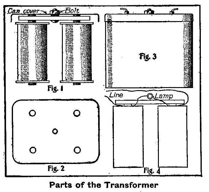
Parts of the Transformer
Secure two magnets from a telephone bell, or a set of magnets
wound for 2,000 ohms. Mount them on a bar of brass or steel as
shown in Fig. 1. Get an empty cocoa can and clean it good to
remove all particles of cocoa and punch five holes in the cover,
as shown in Fig. 2. The middle hole is to be used to fasten the
cover to the brass bar with a bolt. The other four holes are for
the wire terminals. A piece of rubber tubing must be placed over
the wire terminals before inserting them in the holes. Fill the
can with crude oil, or with any kind of oil except kerosene oil,
and immerse the magnets in it by fitting the cover on tight (Fig.
3). The connections are made as shown in the diagram, Fig. 5.
This device may be used on 110-volt current for electro-plating
and small battery lamps, provided the magnets are wound with wire
no larger than No. 40.
Contributed by C. M. Rubsan, Muskogee, Okla.
Experiment with a Vacuum
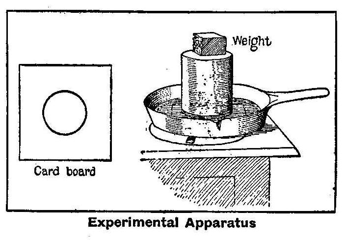
Experimental Apparatus
Take any kitchen utensil used for frying purposes-an ordinary
skillet, or spider, works best-having a smooth inner bottom
surface, and turn in water to the depth of 1/2 in. Cut a piece of
cardboard circular to fit the bottom of the spider and make a
hole in the center 4 in. in diameter. The hole will need to
correspond to the size of the can used. It should be 1 in. less
in diameter than that of the can. Place this cardboard in the
bottom of the spider under the water. A 2-qt. syrup can or pail
renders the best demonstration, although good results may be
obtained from the use of an ordinary tomato can. The edge of
the can must have no indentations, so it will fit perfectly tight
all around on the cardboard. Place the can bottom side up and
evenly over the hole in the cardboard. Put a sufficient weight on
the can to prevent it moving on the cardboard, but not too heavy,
say, l lb.
Place the spider with its adjusted contents upon a heated stove.
Soon the inverted can will begin to agitate. When this agitation
finally ceases remove the spider from the stove, being careful
not to move the can, and if the quickest results are desired,
apply snow, ice or cold water to the surface of the can until the
sides begin to flatten.
The spider with its entire contents may now be lifted by taking
hold of the can. When the vacuum is complete the sides of the can
will suddenly collapse, and sometimes, with a considerable
report, jump from the spider.
The cause of the foregoing phenomenon is that the circular
hole in the cardboard admits direct heat from the surface of the
spider. This heat causes the air in the can to expand, which is
allowed to escape by agitation, the water and the cardboard
acting as a valve to prevent its re-entrance. When the enclosed
air is expelled by the heat and a vacuum is formed by the
cooling, the above results are obtained as described.
Contributed by N. J. McLean.
The Making of Freak Photographs
Photographing the Photographer
An experiment that is interesting and one that can be varied at
the pleasure of the operator, is the taking of his own picture.
The effect secured, as shown in the accompanying sketch,
reproduced in pen and ink from a photograph, is that made by the
photographer himself. At first it seems impossible to secure such
a picture, but when told that a mirror was used the process is
then known to be a simple one.
The mirror is set in such a way as to allow the camera and
operator, when standing directly in front of it, to be in a
rather strong light. The camera is focused, shutter set and plate
holder made ready. The focusing cloth is thrown over your head,
the position taken as shown, and the exposure made by the
pressure of the teeth on the bulb while held between them.
Hand Car Made of Pipe and Fittings
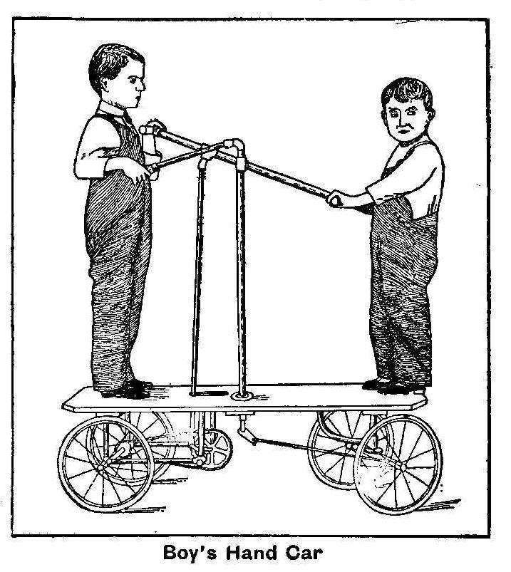
Boy’s Hand Car
Although apparently complicated, the construction of the
miniature hand car shown in the accompanying illustration is very
simple. With a few exceptions all the parts are short lengths of
pipe and common tees, elbows and nipples.
The wheels were manufactured for use on a baby carriage. The
sprocket wheel and chain were taken from a discarded bicycle,
which was also drawn upon for the cork handle used on the
steering lever. The floor is made of 1-in. white pine, 14 in.
wide and 48 in. long, to which are bolted ordinary flanges to
hold the framing and the propelling and steering apparatus
together. The axles were made from 3/8 in. shafting. The fifth
wheel consists of two small flanges working on the face surfaces.
These flanges and the auxiliary steering rod are connected to the
axles by means of holes stamped in the piece of sheet iron which
encases the axle. The sheet iron was first properly stamped and
then bent around the axle. The levers for propelling and steering
the car work in fulcrums made for use in lever valves. The turned
wooden handles by which these levers are operated were inserted
through holes drilled in the connecting tees. The working joint
for the steering and hand levers consists of a 1/2 by 3/8 by 3/8
in. tee, a 1/2 by 3/8 in. cross and a piece of rod threaded on
both ends and screwed into the tee. The cross is reamed and, with
the rod, forms a bearing.
The operation of this little hand car is very similar in
principle to that of the ordinary tricycle, says Domestic
Engineering. The machine can be propelled as fast as a boy can
run. It responds readily to the slightest movement of the
steering lever.
How to Make a Rustic Seat
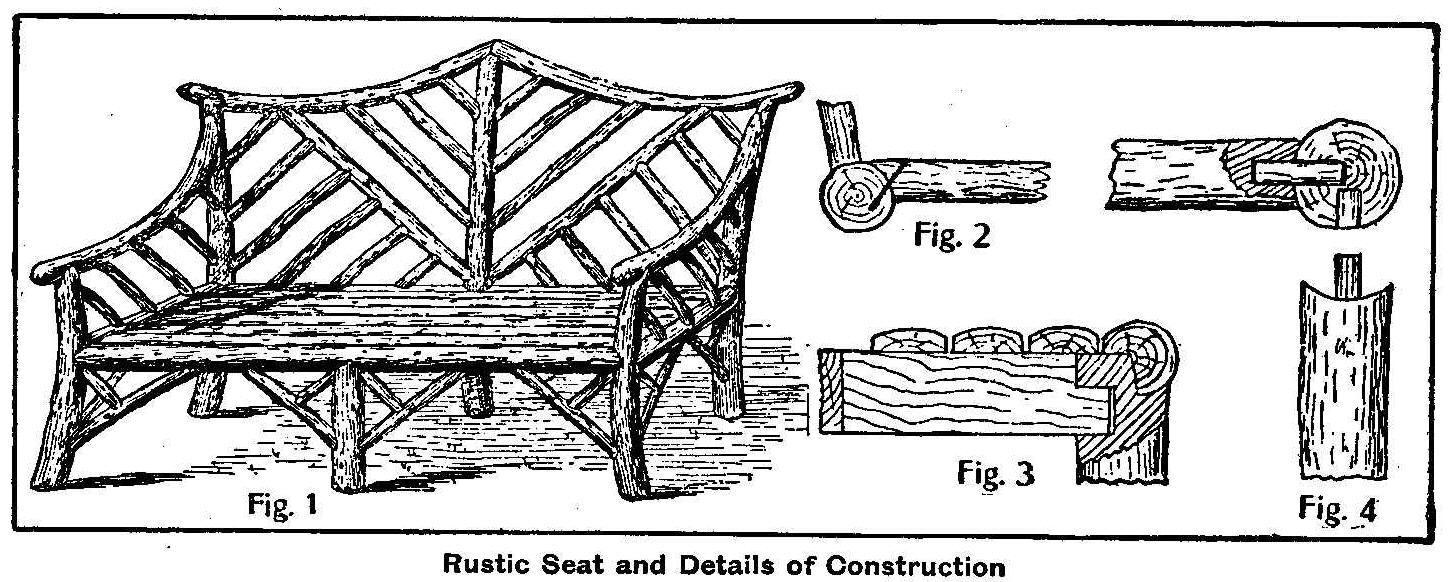
Rustic Seat and Details of Construction
The rustic settee illustrated in Fig. 1 may be made 6 ft. long,
which will accommodate four average-sized persons. It is not
advisable to exceed this length, as then it would look out of
proportion, says the Wood-Worker. Select the material for the
posts, and for preference branches that are slightly curved, as
shown in the sketch. The front posts are about 3-1/2 in. in
diameter by 2 ft. 4 in. long. The back posts are 3 ft. 4 in.
high, while the center post is 3 ft. 8 in. in height. The
longitudinal and transverse rails are about 3 in. in diameter and
their ends are pared away to fit the post to which they are
connected by 1-in. diameter dowels. This method is shown in Fig.
4. The dowel holes are bored at a distance of 1 ft. 2-1/2 in, up
from the lower ends of posts. The front center leg is partially
halved to the front rail and also connected to the back post by a
bearer, 4 in. deep by 1-1/2 in. thick. This bearer is tenoned to
the back post.
Fig. 3 shows a sectional view of the bearer joint to front leg,
and also the half-round seat battens resting on the bearer, also
showing them with their edges planed. It is advisable to have a
space between the edges of each batten, say about 1-8 in., to
allow rainwater to drain. The ends of the seat battens are pared
away to fit the transverse rails neatly as shown in Fig. 2. The
struts for the post range in diameter from 1-1/2 in. to 2 in. The
ends of the struts are pared to fit the posts and rails, and are
then secured with two or three brads at each end.
Select curved pieces, about 2-1/2 in. in diameter, for the arm
rests and back rails; while the diagonally placed filling may be
about 2 in. in diameter. Start with the shortest lengths, cutting
them longer than required, as the paring necessary to fit them to
the rails and posts shortens them a little. Brad them in position
as they are fitted, and try to arrange them at regular intervals.
Heated Steering Wheel
Motorists that suffer with cold hands while driving their cars
may have relief by using a steering wheel that is provided with
electric heat. An English invention describes a steering wheel
with a core that carries two electrically heated coils insulated
one from the other and from the outer rim.
Homemade Workbench
By C. E. McKinney, Jr.
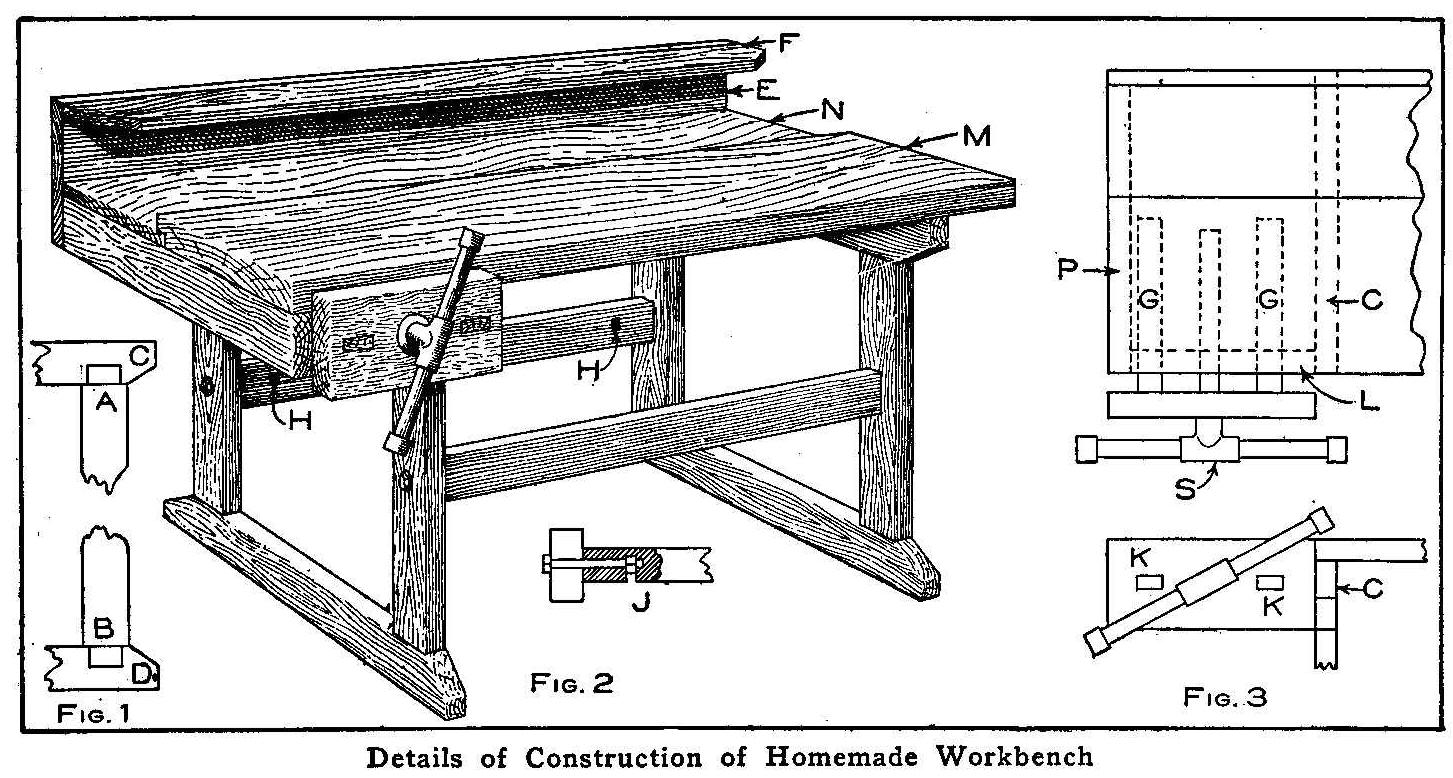
Details of Construction of Homemade Workbench
The first appliance necessary for the boy’s workshop is a
workbench. The average boy that desires to construct his own
apparatus as much as possible can make the bench as described
herein. Four pieces of 2 by 4-in. pine are cut 23 in. long for
the legs, and a tenon made on each end of them, 1/2 in. thick,
3-1/2 in. wide and 1-1/2 in. long, as shown at A and B, Fig. 1.
The crosspieces at the top and bottom of the legs are made from
the same material and cut 20 in. long. A mortise is made 1-1/4
in. from each end of these pieces and in the narrow edge of them,
as shown at C and D, Fig. 1. The corners are then cut sloping
from the edge of the leg out and to the middle of the piece, as
shown. When each pair of legs are fitted to a pair of crosspieces
they will form the two supports for the bench. These supports are
held together and braced with two braces or connecting pieces of
2 by 4-in. pine, 24 in. long. The joints are made between the
ends of these pieces and the legs by boring a hole through each
leg and into the center of each end of the braces to a depth of 4
in., as shown at J, Fig. 2. On the back side of the braces bore
holes, intersecting the other holes, for a place to insert the
nut of a bolt, as shown at HH. Four 3/8 by 6-in, bolts are placed
in the holes bored, and the joints are drawn together as shown at
J. The ends of the two braces must be sawed off perfectly square
to make the supports stand up straight.
In making this part of the bench be sure to have the joints fit
closely and to draw the bolts up tight on the stretchers. There
is nothing quite so annoying as to have the bench support sway
while work is being done on its top. It would be well to add a
cross brace on the back side to prevent any rocking while planing
boards, if the bench is to be used for large work.
The main top board M, Fig. 2, may be either made from one piece
of 2 by 12-in. plank, 3-1/2 ft. long, or made up of 14 strips of
maple, 7/8 in. thick by 2 in. wide and 3-1/2 ft. long, set on
edge, each strip glued and screwed to its neighbor. When building
up a top like this be careful to put the strips together with the
grain running in the same direction so the top may be planed
smooth. The back board N is the same length as the main top board
M, 8-1/2 in. wide and only 7/8 in. thick, which is fitted into a
1/2-in. rabbet in the back of the board M. These boards form the top
of the bench, and are fastened to the top pieces of the supports
with long screws. The board E is 10 in. wide and nailed to the
back of the bench. On top of this board and at right angles with
it is fastened a 2-1/2 in. board, F. These two boards are 7/8 in.
thick and 3-1/2 ft. long. Holes are bored or notches are cut in
the projecting board, F, to hold tools.
Details of the vise are shown in Fig. 3, which is composed of a 2
by 6-in. block 12 in. long, into which is fastened an iron bench
screw, S. Two guide rails, GG, 7/8 by 1-1/2 in. and 20 in. long,
are fastened into mortises of the block as shown at KK, and they
slide in corresponding mortises in a piece of 2 by 4-in. pine
bolted to the under side of the main top board as shown at L. The
bench screw nut is fastened in the 2 by 4-in. piece, L, between
the two mortised holes. This piece, L, is securely nailed to one
of the top cross pieces, C, of the supports and to a piece of 2
by 4-in. pine, P, that is bolted to the under sides of the top
boards at the end of the bench. The bolts and the bench screw can
be purchased from any hardware store for less than one dollar.
Forming Coils to Make Flexible Wire Connections
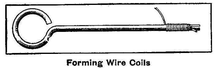
Forming Wire Coils
When connections are made to bells and batteries with small
copper wires covered with cotton or silk, it is necessary to have
a coil in a short piece of the line to make it flexible. A good
way to do this is to provide a short rod about 3/16 in. in
diameter cut with a slit in one end to hold the wire and a loop
made on the other end to turn with the fingers. The end of the
wire is placed in the slit and the coil made around the rod by
turning with the loop end.
Photographing the North Star
Photograph of the North Star
The earth revolving as upon an axis is inclined in such a
position that it points toward the North Star. To an observer in
the northern hemisphere the effect is the same as if the heavens
revolved with the North star as a center. A plate exposed in a
camera which is pointed toward that part of the sky on a clear
night records that effect in a striking manner. The accompanying
illustration is from a photograph taken with an exposure of about
three hours, and the trace of the stars shown on the plate by a
series of concentric circles are due to the rotation of the
earth.
The bright arc of the circle nearest the center is the path of
the North star. The other arcs are the impressions left by
neighboring stars, and it will be noticed that their brightness
varies with their relative brilliancy. Many are so faint as to be
scarcely distinguished, and, of course, telescopic power would
reveal myriads of heavenly bodies which leave no trace on a plate
in an ordinary camera. The North or pole star is commonly
considered at a point directly out from the axis of the earth,
but the photograph shows that it is not so located. The variation
is known astronomically to be 1-1/4 deg. There is a slight
irregularity in the position of the earth’s axis, but the changes
are so slow as to be noticed only by the lapse of a thousand
years. Five thousand years ago the pole star was Draconis, and in
eighteen thousand years it will be Lyrae. We have direct evidence
of the change of the earth’s axis in one of the Egyptian pyramids
where an aperture marked the position of the pole star in ancient
times, and from this it is now deviated considerable.
This experiment is within the reach of everyone owning a camera.
The photograph shown was taken by an ordinary instrument, using a
standard plate of common speed. The largest stop was used and the
only requirement beyond this is to adjust the camera in a
position at the proper inclination and to make the exposure for
as long as desired. On long winter nights the exposure may be
extended to 12 hours, in which event the curves would be
lengthened to full half-circles.
The North star is one of the easiest to locate in the entire
heavens. The constellation known as the Great Dipper is near by,
and the two stars that mark the corners of the dipper on the
extremity farthest from the handle lie in a line that passes
across the North star. These two stars in the Great Dipper are
called the pointers. The North Star is of considerable
brilliancy, though by no means the brightest in that part of the
heavens.
Contributed by C. S. B.
How to Relight a Match
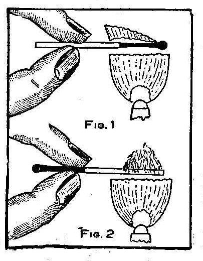
A match may be a small thing on which to practice economy and yet
a great many times one wishes to relight a match either for
economy or necessity. The usual method is to place the burnt
portion of the match in the flame to be relighted as shown in
Fig. 1. It is very hard to relight the charred end and usually
burnt fingers are the result of pushing the match farther in the
flame. Hold the burnt end in the fingers and place the other end
in the flame as shown in Fig. 2. A light will be secured quickly
and the flame will only follow the stick to the old burnt
portion.
Home-Made Hand Drill
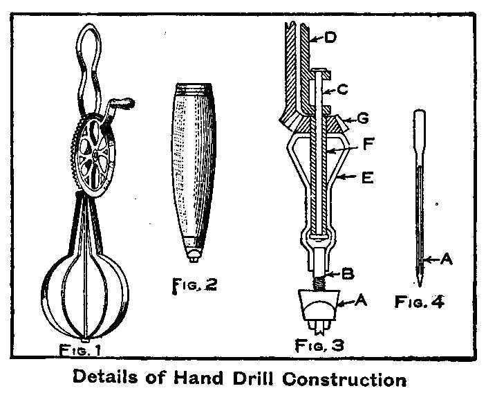
Details of Hand Drill Construction
In the old kitchen tool box I found a rusty egg beater of the
type shown in Fig. 1. A shoemaker friend donated a pegging awl,
Fig. 2, discarded by him due to a broken handle. With these two
pieces of apparatus I made a hand drill for light work in wood or
metal. By referring to Fig. 3 the chuck, A, with stem, B, were
taken from the awl. The long wire beater was taken from the
beater frame and a wire nail, C, soldered to the frame, D, in the
place of the wire. The flat arms were cut off and shaped as shown
by E. The hole in the small gear, G, was drilled out and a tube,
F, fitted and soldered to both the gear and the arms E. This
tube, with the gear and arms, was slipped over the nail, C, then
a washer and, after cutting to the proper length the nail was
riveted to make a loose yet neat fit for the small gear. The hand
drill was then completed by soldering the stem, B, of the chuck
to the ends of the flat arms E. Drills were made by breaking off
sewing-machine needles above the eye as shown in Fig. 4 at A, and
the end ground to a drill point.
Contributed by R. B. J., Shippensburg, Pa.
How to Make a Stationary Windmill
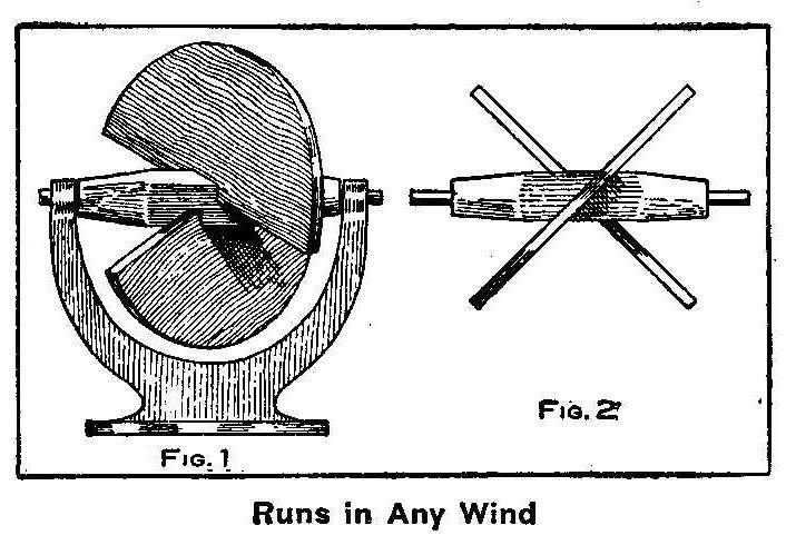
Runs in Any Wind
A windmill that can be made stationary and will run regardless of
the direction of the wind is here illustrated. Mills of this kind
can be built of larger size and in some localities have been used
for pumping water.
Two semi-circular surfaces are secured to the axle at right
angles to each other and at 45 deg. angle with that of the axle
as shown in Fig. 2. This axle and wings are mounted in bearings
on a solid or stationary stand or frame. By mounting a pulley on
the axle with the wings it can be used to run toy machinery.
Electric Anesthesia
It is a well known fact that magnetism is used to demagnetize a
watch, and that frost is drawn out of a frozen member of the body
by the application of snow. Heat is also drawn out of a burned
hand by holding it close to the fire, then gradually drawing it
away. The following experiment will show how a comparatively
feeble electric current can undo the work of a strong one.
I once tried to electrocute a rat which was caught in a wire
basket trap and accidentally discovered a painless method. I say
painless, because the rodent does not object to a second or third
experiment after recovering, and is apparently rigid and without
feeling while under its influence.
To those who would like to try the experiment I will say that my
outfit consisted of an induction coil with a 3/8-in. iron core
about 3 in. long. The primary coil was wound with four layers
of No. 20 wire and the secondary contains 4 oz. No. 32 wire, and
used on one cell of bichromate of potash plunge battery. The
proper amount of current used can be determined by giving the
rodent as much as a healthy man would care to take. Fasten one
secondary electrode to the trap containing the rat and with a
wire nail fastened to the other terminal, hold the vibrator of
the coil with your finger and let the rat bite on the nail and
while doing so release the vibrator. In three seconds the rat
will be as rigid as if dead and the wires can be removed.
Now connect your wires to the primary binding-posts of the coil
and wind the end of one of them around the rat’s tail and start
the vibrator. Touch the other terminal to the rat’s ear and nose.
In a few minutes he will be as lively as ever.
Contributed by Chas. Haeusser, Albany, N. Y.
A Simple Battery Rheostat
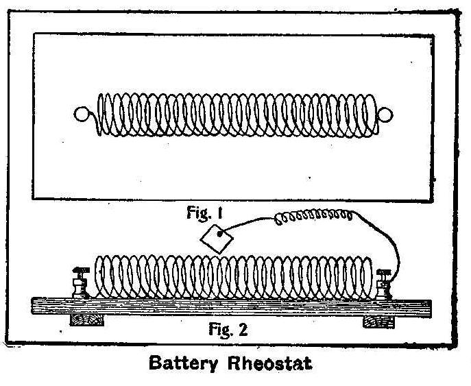
Battery Rheostat
A spring from an old shade roller is mounted on a board 4 in.
wide, 9 in. long and 3/8 in. thick. A binding-post is fastened to
this board at each end, to which is attached the ends of the
spring, as shown in Fig. 1. The temper of a small portion of each
end of the spring will need to be drawn. This can be accomplished
by heating over an alcohol lamp or in a fire and allowing it to
cool slowly. The ends are then shaped to fit the binding-posts. A
wire is connected to one of the binding-posts and a small square
piece of copper is attached to the other end of the wire, as
shown in Fig. 2. When this device is placed in a circuit the
current can be regulated by sliding the small square copper piece
along the spring.
Contributed by H. D. Harkins, St. Louis, Mo.
A Frame for Drying Films
No doubt many amateur photographers are troubled about drying
films and to keep them from curling. The problem may be solved in
the following way: Make a rectangular frame out of pine wood, 1/4
by 1/2 in., as shown in the sketch. It is made a little wider and
a little shorter than the film to be dried. This will allow the
end of the film to be turned over at each end of the frame and
fastened with push pins. Do not stretch the film when putting it
on the frame as it shrinks in drying. The film will dry quicker
and will be flat when dried by using this frame.
Contributed by Elmer H. Flehr, Ironton, Ohio.
A Home-Made Novelty Clock
This clock that is shown in the accompanying engraving is made in
scroll work, the cathedral and towers being of white maple, the
base is of walnut with mahogany trimmings, all finished in their
natural colors. It has 11 bells in the two towers at the sides
and 13 miniature electric lamps of different colors on two
electric circuits. The clock is operated by a small motor
receiving its power from dry cell batteries. This motor turns a
brass cylinder over which runs a continuous roll of perforated
paper similar to that used on a pianola. A series of metal
fingers, connected by wires to the bells, press lightly on this
brass roll and are insulated from the roll by the perforated
paper passing between. When a perforation is reached a finger
will make a contact with the brass roll for an instant which
makes a circuit with the magnet of an electric hammer in its
respective bell or forms the circuit which lights the electric
bulbs as the case may be.
At each hour and half hour as the clock strikes, the motor is
started automatically and the chimes sound out the tunes while
the colored lights are turned on and off; two small doors in the
cathedral open and a small figure comes out while the chimes are
playing, then returns and the doors are closed.
Contributed by C. V. Brokenicky, Blue Rapids, Kansas.
Fourth-of-July Catapult
Homemade Cannon Which will Hurl a Life-Size Dummy 100 Ft. through the Air
Among the numerous exciting amusements in which boys may
participate during the Fourth-of-July celebration is to make a
cannon that will shoot life-sized dummies dressed in old clothes.
Building the cannon, as described in the following, makes it safe
to fire and not dangerous to others, provided care is taken to
place it at an angle of 45 deg. and not to fire when anyone is
within its range. The powder charge is in the safest form
possible, as it is fired with a blow from a hammer instead of
lighting a fuse. If the cannon is made according to directions,
there cannot possibly be any explosion.
The materials used in the construction of the catapult may be
found in almost any junk pile, and the only work required,
outside of what can be done at home, is to have a few threads cut
on the pieces of pipe. The fittings can be procured ready to
attach, except for drilling a hole for the firing pin.
Secure a piece of common gas pipe, 4 to 6 in. in diameter, the
length being from 18 to 24 in. Old pipe may be used if it is
straight. Have a machinist cut threads on the outside of one end,
as shown in Fig. 1, and fit an iron cap, Fig. 2, tightly on the
threaded end of the pipe. The cap is drilled and tapped in the
center for a 1-in. pipe. Thread both ends of a 1-in. pipe that is
4 in. long, Fig. 3, and turn one end securely into the threaded
hole of the cap. This pipe should project 1/4 in. inside of the
cap. Fit a cap, Fig. 4, loosely on the other end of the 1-in.
pipe. A hole is drilled into the center of this small cap just
large enough to receive a 6-penny wire nail, B, Fig. 4.
This completes the making of the cannon and the next step is to
construct a dummy which can be dressed in old clothes. Cut out
two round blocks of wood from hard pine or oak that is about 3
in. thick, as shown in Fig. 5. The diameter of these blocks
should be about 1/8 in. less than the hole in the cannon, so they
will slide easily. In the center of each block bore a 1/4-in.
hole. Secure an iron rod, about 4 ft. long, and make a ring at
one end and thread 4 in. of the other. Slip one of the circular
blocks on the rod and move it up toward the ring about 14 in.
Turn a nut on the threads, stopping it about 3-1/2 in. from the
end of the rod. Slip the other circular piece of wood on the rod
and up against the nut, and turn on another nut to hold the
wooden block firmly in its place at the end of the rod. If the
rod is flattened at the place where the upper block is located,
it will hold tight. These are shown in Fig. 5. Take some iron
wire about 1/8 in. in diameter and make a loop at the top of the
rod for the head. Wire this loop to the ring made in the rod and
make the head about this loop by using canvas or gunny cloth
sewed up forming a bag into which is stuffed either excelsior,
paper or hay. The arms are made by lashing with fine wire or
strong hemp, a piece of wood 1 in. square and 20 in. long, or one
cut in the shape shown in Fig. 6, to the rod. Place the wood arms
close to the bottom of the head. Make a triangle of wire and
fasten it and the cross arm securely to the top of the rod to
keep them from slipping down. A false face, or one painted on
white cloth, can be sewed on the stuffed bag. An old coat and
trousers are put on the frame to complete the dummy. If the
clothing is not too heavy and of white material so much the
better. To greatly increase the spectacular flight through the
air, a number of different colored streamers, 6 or 8 in. wide and
several feet in length made from bunting, can be attached about
the waist of the dummy. The complete dummy should not weigh more
than 6 lb.
The cannon is mounted on a board with the cap end resting against
a cleat which is securely nailed to the board and then bound
tightly with a rope as shown in Fig. 8. Lay one end of the board
on the ground and place the other on boxes or supports
sufficiently high to incline it at an angle of about 45. deg.
Enough of the board should project beyond the end of the cannon
on which to lay the dummy. When completed as described, it is
then ready to load and fire. Clear away everyone in front and on
each side of the cannon, as the dummy will fly from 50 to 100 ft.
and no one must be in range of its flight. This is important, as
the rod of the frame holding the clothes will penetrate a board
at short range. An ordinary shot gun cartridge of the paper shell
type is used for the charge and it must be loaded with powder
only. Coarse black powder is the best, but any size will do. When
loading the rod with the wooden blocks, on which the dummy is
attached, do not place the end block against the breech end of
the cannon, leave about 2 or 3 in. between the end of the cannon
and the block. Insert the cartridge in the 1-in. pipe. The
cartridge should fit the pipe snug, which it will do if the
proper size is secured. Screw on the firing-cap, insert the wire
nail firing pin until it rests against the firing-cap of the
cartridge. If the range is clear the firing may be done by giving
the nail a sharp rap with a hammer. A loud report will follow
with a cloud of smoke and the dummy will be seen flying through
the air, the arms, legs and streamers fluttering, which presents
a most realistic and life-like appearance. The firing may be
repeated any number of times in the same manner.
How to Make a Miniature Volcano
Volcano in Action
A toy volcano that will send forth flames and ashes with lava
streaming down its sides in real volcanic action can be made by
any boy without any more danger than firing an ordinary fire-cracker.
A mound of sand or earth is built up about 1 ft. high in
the shape of a volcano. Roll up a piece of heavy paper, making a
tube 5 in. long and 1-1/2 in. in diameter. This tube of paper is
placed in the top of the mound by first setting it upon a flat
sheet of paper and building up the sand or earth about the sides
until it is all covered excepting the top opening. This is to
keep all dampness away from the mixture to be placed within.
A fuse from a fire-cracker, or one made by winding some powder in
tissue paper, is placed in the paper tube of the volcano with one
end extending over the edge. Get some potash from a drug store
and be sure to state the purpose for which it is wanted, as there
are numerous kinds of potash that will not be suitable. An equal
amount of sugar is mixed with the potash and placed in the paper
tube. On top of this put a layer of pure potash and on this pour
some gun powder. This completes the volcano and it only remains
for the fuse to be lighted and action will begin with an
explosion which sends fire, smoke and sparks upward. Flames will
follow and the lava pours down the sides of the mound.
Wire Loop Connections for Battery Binding-Posts
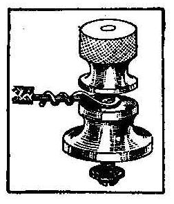
The trouble with battery binding post connections can be avoided
by winding the bare end of the connecting wire around the
binding-post screw and then back around its extending length as
shown in the sketch. Always screw down permanent connections with
pliers.
Melting Metal in the Flame of a Match
The flame of an ordinary match has a much higher temperature than
is generally known and will melt cast-iron or steel filings. Try
it by striking a match and sprinkle the filings through the
flame. Sputtering sparks like gunpowder will be the result of the
melting metal.
Russian Squirrels
The squirrel slaughter of Russia amounts to 25,000,000 per year.
Landscape Drawing Made Easy
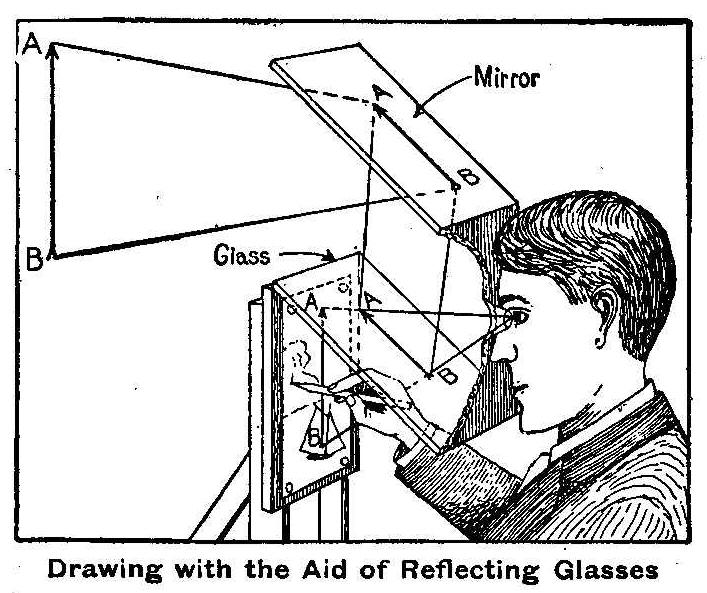
Drawing with the Aid of Reflecting Glasses
With this device anyone, no matter how little his artistic
ability may be, can draw accurately and quickly any little bit of
scenery or other subject and get everything in the true
perspective and in the correct proportion.
No lens is required for making this camera-just a plain mirror
set at an angle of 45 deg., with a piece of ordinary glass
underneath, a screen with a peek hole and a board for holding the
drawing paper. The different parts may be fastened together by
means of a box frame, or may be hinged together to allow folding
up when carrying and a good tripod of heavy design should be used
for supporting it. In order to get the best results the screen
should be blackened on the inside and the eyepiece should be
blackened on the side next to the eye. A piece of black cardboard
placed over the end of the eyepiece and perforated with a pin
makes an excellent peek hole.
In operation the rays of light coming from any given object, such
as the arrow AB, strike the inclined mirror and are reflected
downward. On striking the inclined glass a portion of the light
is again reflected and the rays entering the eye of the operator
produce the virtual image on the paper as shown. The general
outlines may be sketched in quickly, leaving the details to be
worked up later. This arrangement may be used for interior work
when the illumination is good.
Irrigating with Tomato Cans
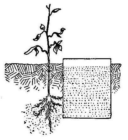
The following is an easy and effective way to start plants in dry
weather: Sink an ordinary tomato can, with a 1/8-in. hole 1/2 in.
from the bottom, in the ground so that the hole will be near the
roots of the plant. Tamp the dirt around both plant and can, and
fill the latter with water. Keep the can filled until the plant
is out of danger.
Contributed by L. L. Schweiger, Kansas City, Mo.
Fountain for an Ordinary Pen
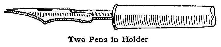
Two Pens In Holder
Take two steel pens, not the straight kind, and place them
together, one above the other, in the penholder. With one dip of
ink 60 or 70 words may be written. This saves time and the
arrangement also prevents the ink from dropping off the pen.
Contributed by L. M. Lytle, Kerrmoor, Pa.
Homemade Mousetrap
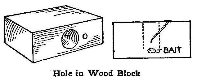
Hole In Wood Block
Bore a 1-in. hole, about 2 in. deep, in a block of wood and drive
a small nail with a sharp point at an angle so it will project
into the hole about half way between the top and bottom, and in
the center of the hole, as shown. File the end very sharp and
bend it down so that when the mouse pushes its head past it in
trying to get the bait at the bottom of the hole, the sharp point
will catch it when it tries to back out. Almost anyone can make
this trap in a short time, and it will catch the mice as surely
as a more elaborate trap.
Clear Wax Impressions from Seals
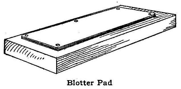
Blotter Pad
A die must be slightly damp to make clear impressions on sealing
wax and to keep it from sticking to the wax. A very handy way to
moisten the die is to use a pad made by tacking two pieces of
blotting paper and one of cloth to a wooden block of suitable
size, and saturate the blotters with water before using. Stamp
the die on the pad and then on the hot wax. The result will be a
clear, readable impression.
Contributed by Fred Schumacher, Brooklyn, N. Y.
A Window Stick
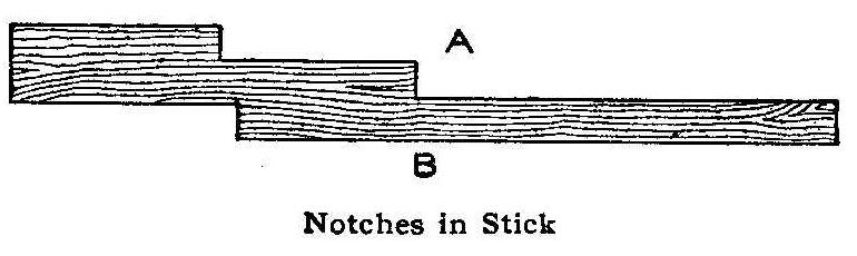
Notches In Stick
Although the windows in factories and houses are usually provided
with weights, yet the stick shown in the sketch will be found
very handy in case all of the windows are not so equipped. It is
made of a piece of pine wood long enough to hold the lower sash
at a height even with the bottom of the upper, and about 1-1/2 or
2 in. wide. Notches may be cut in the stick as shown, each being
wide enough to firmly hold the sash. Thus, with the stick
illustrated, the sash may be held at three different heights on
the side A, and at still another on the side B.
Contributed by Katharine D. Morse, Syracuse, N. Y.
How to Make a Canoe
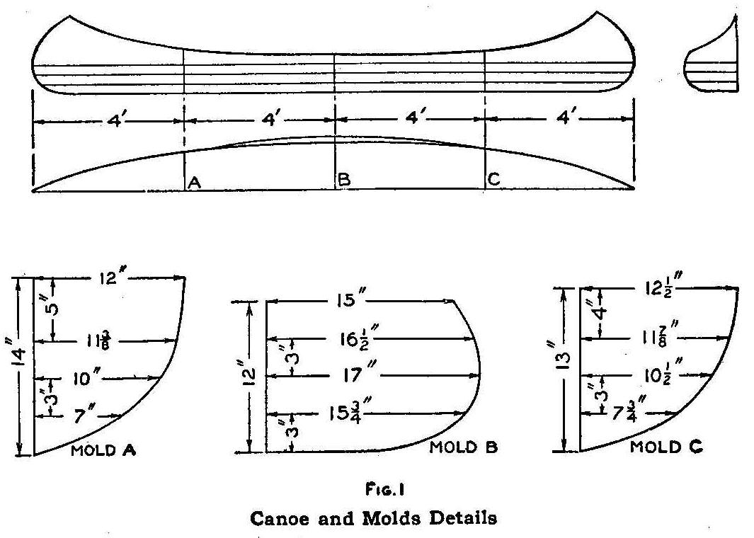
Canoe and Molds Details
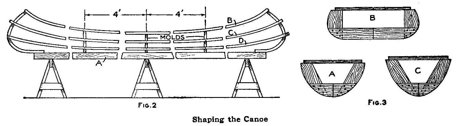
Shaping the Canoe
A practical and serviceable canoe, one that is inexpensive, can
be built by any boy, who can wield hammer and saw, by closely
following the instructions and drawings, given in this article.
It is well to study these carefully before beginning the actual
work. Thus an understanding will be gained of how the parts fit
together, and of the way to proceed with the work.
Dimensioned drawings of the canoe and molds are contained in Fig.
1. The boat is built on a temporary base, A, Fig. 2, which is a
board, 14 ft. 1 in. long, 3 in. wide and 1-1/2 in. thick. This
base is fastened to the trestles and divided into four sections,
the sections on each side of the center being 4 ft. long.
The next thing to be considered are the molds (Fig. 3). These are
made of 1-in. material. Scrap pieces may be found that can be
used for these molds. The dimensions given in Fig 1 are for
one-half of each form as shown in Fig. 3, under their respective
letters. The molds are then temporarily attached to the base on
the division lines. Proceed to make the curved ends as shown in
Fig. 4. Two pieces of straight-grained green elm, 32 in. long,
1-3/4, in. wide and 1 in. thick, will be required. The elm can be
obtained from a carriage or blacksmith’s shop. The pieces are
bent by wrapping a piece of wire around the upper end and
baseboard. The joint between the curved piece and the base is
temporary. Place a stick between the wires and twist them until
the required shape is secured. If the wood does not bend readily,
soak it in boiling water. The vertical height and the horizontal
length of this bend are shown in Fig. 4. The twisted wire will
give the right curve and hold the wood in shape until it is dry.
The gunwales are the long pieces B, Fig. 2, at the top of the
canoe. These are made of strips of ash, 15 ft. long, 1 in. wide
and 1 in. thick. Fasten them temporarily to the molds, taking
care to have them snugly fit the notches shown. The ends fit over
the outside of the stem and stern pieces and are cut to form a
sharp point, as shown in Fig. 5. The ends of the gunwales are
fastened permanently to the upper ends of the bent stem and stern
pieces with several screws.
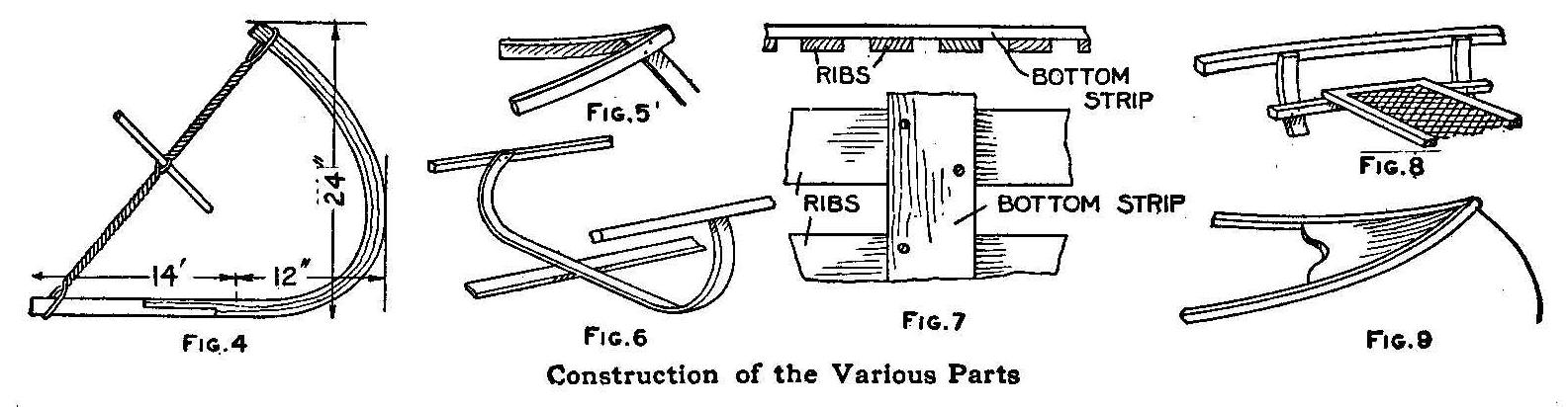
Construction of the Various Parts
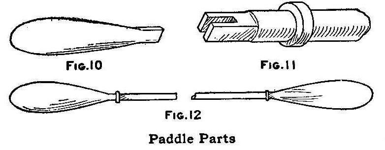
Paddle Parts
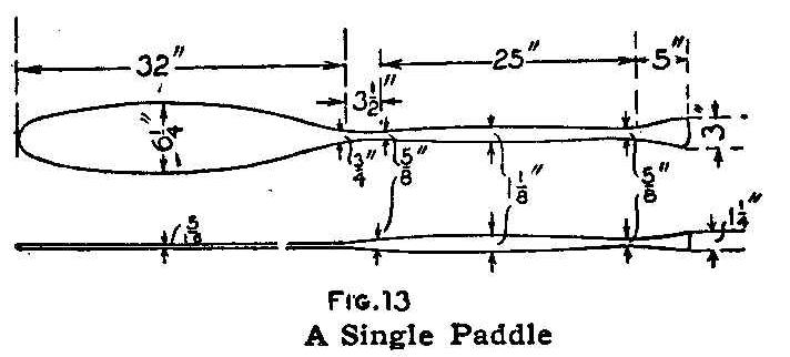
A Single Paddle
Two other light strips, C and D, Fig. 2, are temporarily put in,
and evenly spaced between the gunwales and the bottom board.
These strips are used to give the form to the ribs, and are
removed when they have served their purpose.
The ribs are now put in place. They are formed of strips of well
seasoned elm or hickory, soaked in boiling water until they bend
without breaking or cracking. Each rib should be 1-1/2 in. wide,
3/8 in. thick and long enough to reach the distance between the
gunwales after the bend is made. The ribs are placed 1 in. apart.
Begin by placing a rib in the center of the base and on the upper
side. Nail it temporarily, yet securely, and then curve the ends
and place them inside of the gunwales, as shown in Fig. 6. Fasten
the ends of the rib to the gunwales with 1-in. galvanized brads.
This method is used in placing all the ribs. When the ribs are
set, remove the pieces C and D, Fig. 2, and the molds.
A strip is now put in to take the place of the base. This strip
is 1-3/4 in. wide, 1/2 in. thick and long enough to reach the
entire length of the bottom of the canoe. It is fastened with
screws on the inside, as shown in Fig. 7, and the ends are
lap-jointed to the stem and stern pieces as shown in Fig. 4. When
this piece is fastened in place, the base can be removed. The
seats are attached as shown in Fig. 8, and the small pieces for
each end are fitted as shown in Fig. 9.
The frame of the canoe is now ready to be covered. This will
require 5-1/2 yd. of extra-heavy canvas. Turn the framework of
the canoe upside down and place the canvas on it. The center of
the canvas is located and tacked to the center strip of the canoe
at the points where ribs are attached. Copper tacks should be
used. The canvas is then tacked to the ribs, beginning at the
center rib and working toward each end, carefully drawing the
canvas as tightly as possible and keeping it straight. At the
ends the canvas is split in the center and lapped over the bent
wood. The surplus canvas is cut off. A thin coat of glue is put
on, to shrink the cloth and make it waterproof.
The glue should be powdered and brought into liquid form in a
double boiler. A thin coat of this is applied with a paintbrush.
A small keel made of a strip of wood is placed on the bottom to
protect it when making a landing on sand and stones in shallow
water. When the glue is thoroughly dry the canvas is covered with
two coats of paint, made up in any color with the best lead and
boiled linseed oil. The inside is coated with spar varnish to
give it a wood color.
The paddles may be made up in two ways, single or double. The
double paddle has a hickory pole, 7 ft. long and 2 in. in
diameter, for its center part. The paddle is made as shown in
Fig. 10, of ash or cypress. It is 12 in. long, and 8 in. wide at
the widest part. The paddle end fits into a notch cut in the end
of the pole (Fig. 11). A shield is made of a piece of tin or
rubber and placed around the pole near the paddle to prevent the
water from running to the center as the pole is tipped from side
to side. The complete paddle is shown in Fig. 12. A single paddle
is made as shown in Fig. 13. This is made of ash or any other
tough wood. The dimensions given in the sketch are sufficient
without a description.
Thorns Used as Needles on a Phonograph
Very sharp thorns can be used successfully as phonograph needles.
These substitutes will reproduce sound very clearly and with
beautiful tone. The harsh scratching of the ordinary needle is
reduced to a minimum, and the thorn is not injurious to the
record.
Tool Hangers
A tool rack that is serviceable for almost any kind of a tool may
be made by placing rows of different-size screw eyes on a wall
close to the workbench, so that files, chisels, pliers and other
tools, and the handles of hammers can be slipped through the
eyes.
A place for every tool saves time, and besides, when the tools
are hung up separately, they are less likely to be damaged, than
when kept together on the work-bench.
Child’s Footrest on an Ordinary Chair
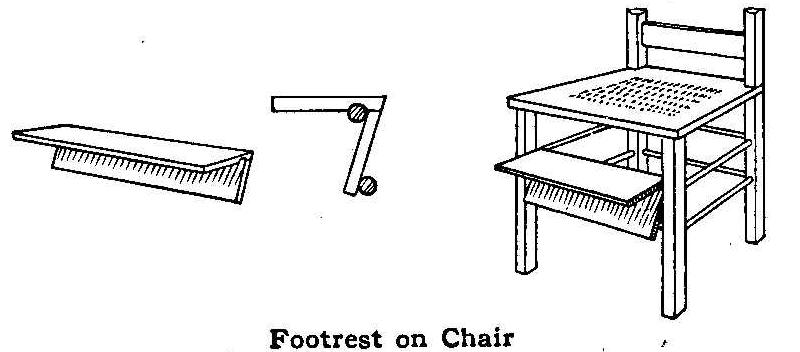
Footrest on Chair
Small chairs are enjoyed very much by children for the reason
that they can rest their feet on the floor. In many households
there are no small chairs for the youngsters, and they have to
use larger ones. Two things result, the child’s legs become tired
from dangling unsupported or by trying to support them on the
stretchers, and the finish on the chair is apt to be scratched.
The device shown in the sketch forms a footrest or step that can
be placed on any chair. It can be put on or taken off in a
moment. Two suitable pieces of wood are nailed together at an
angle and a small notch cut out, as shown, to fit the chair
stretcher.
Drying Photo Postal Cards
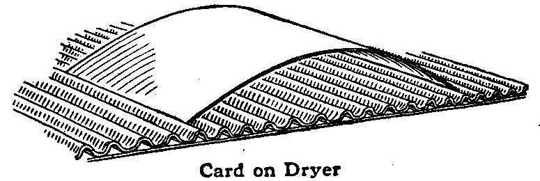
Card on Dryer
A novel idea for drying photo postal cards comes from a French
magazine. The drying of the cards takes a long time on account of
their thickness, but may be hastened by using corrugated paper
for packing bottles as a drying stand. Curve the cards, printed
side up, and place the ends between two corrugations at a
convenient distance apart. They will thus be held firmly while
the air can circulate freely all around them.
Preserving Key Forms
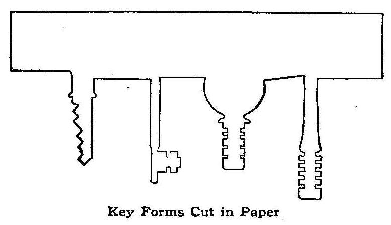
Key Forms Cut in Paper
After losing a key or two and having some difficulty in replacing
them, I used the method shown in the sketch to preserve the
outlines for making new ones. All the keys I had were traced on a
piece of paper and their forms cut out with a pair of shears.
When a key was lost, another could thus be easily made by using
the paper form as a pattern.
Contributed by Ernest Weaver, Santa Anna, Texas.
Renewing Typewriter Ribbons
Roll the ribbon on a spool and meanwhile apply a little glycerine
with a fountain-pen filler. Roll up tightly and lay aside for a
week or ten days. Do not apply too much glycerine as this will
make the ribbon sticky—a very little, well spread, is enough.
The same application will also work well on ink pads.
Contributed by Earl R. Hastings, Corinth, Vt.
Drinking Trough for Chickens
Trough of Roofing Paper
A quickly made and sanitary drinking trough for chickens is
formed of a piece of ordinary two or three-ply roofing paper.
The paper is laid out as shown, and the edges are cemented with
asphaltum and then tacked to the side of a fence or shed.
Ordinary Pen Used as a Fountain Pen
Fountain Attachment
It is a very simple matter to make a good fountain pen out of an
ordinary pen and holder. The device is in the form of an
attachment readily connected to or removed from any ordinary pen
and holder, although the chances are that when once used it will
not be detached until a new pen is needed.
Take the butt end of a quill, A, from a chicken, goose or turkey
feather—the latter preferred as it will hold more ink—and clean
out the membrane in it thoroughly with a wire or hatpin. Then
make a hole in the tapered end of the quill just large enough to
pull through a piece of cotton string. Tie a knot in one end of
this string, B, and pull it through the small end of the quill
until the knot chokes within, then cut off the string so that
only 1/4 in. projects. Shave out a small stopper from a bottle
cork for the large end of the quill. This completes the ink
reservoir.
Place the quill on top of the penholder C, so that its small end
rests against the pen immediately above its eye. Pull the string
through this eye. Securely bind the quill to the pen and holder
with a thread, as shown, first placing under it a wedge-shaped
support of cork or wood, D, hollowed on both sides to fit the
curved surfaces of the quill and holder. The illustration shows
the detail clearly.
To fill the reservoir place the pen upright on its point and dip
a small camel’s-hair brush or cloth-bound toothpick into the ink
bottle and “scrape” off the ink it will hold on the inner edge of
the quill. Cork tightly, and the device is ready for use. When
not in use place the holder at an angle with the pen uppermost.
Contributed by Chelsea C. Fraser, Saginaw, Michigan.
How to Construct a Small Thermostat
By R. A. McClure
Simple Thermostat
Couple and Mounting Strip
It is a well known fact, that there is a change in the dimensions
of a piece of metal, due to a change in its temperature. This
change in dimensions is not the same for all materials; it being
much greater in some materials than in others, while in some
there is practically no change.
If two thin, narrow strips of different metals, that contract or
expand at different ratio due to a variation in temperature, be
rigidly fastened together at their ends, and the combination then
heated or cooled, the combined piece will have its shape changed.
One of the pieces will increase in length more than the other,
due to a rise in temperature, and this same piece will decrease
in length more than the other when subjected to a decrease in
temperature.
If one end of this combined piece be rigidly clamped to a
support, as shown in Fig. 1, and the combination then have its
temperature changed, the free end will move to the right or left
of its original position, depending upon which of the pieces
changes in length the more. If there is a rise in temperature and
the right-hand piece B increases in length faster than the
left-hand piece A, the free end of the combined piece win move to
the left of its original position. If, on the other hand, there
is a decrease in temperature, the right-hand piece will decrease
in length more than the left-hand piece, and the upper or free
end will move to the right of its original position.
Such a combination of two metals constitutes a simple thermostat.
If the movement of the free end of the combination be made to
actuate a needle moving over a properly calibrated scale, we have
a simple form of thermometer. If two electrical contacts, CC, be
mounted on the right and left-hand sides of the upper end of the
combined piece, as shown in Fig. 1, we have a thermostat that may
be used in closing an electrical circuit when the temperature of
the room in which it is placed rises or falls a certain value.
These contacts should be so arranged that they can be moved
toward or away from the combined piece independently. By
adjusting the position of these contacts, the electrical circuit
will be closed when the temperature of the thermostat has reached
an experimentally predetermined value.
The following description is that of a thermostat, constructed by
the author of this article, which gave very satisfactory results.
First obtain a piece of steel, 6 in. long, 5/8 in. wide and 2/100
in. thick, and a piece of brass, 6 in. long, 5/8 in. wide and
3/100 in. thick. Clean one side of each of these pieces and tin
them well with solder. Place the two tinned surfaces just treated
in contact with each other and heat them until the solder on
their surfaces melts and then allow them to cool. A better way
would be to clamp the two thin pieces between two heavy metal
pieces, and then heat the whole to such a temperature that the
solder will melt, and then allow it to cool.
{456}
This last method
will give more satisfactory results than would be obtained if no
clamps are used, as the thin metal pieces are liable to bend out
of shape when they are heated, and as a result they will not be
in contact with each other over their entire surfaces. After
these pieces have been soldered together forming one piece, which
we shall for convenience speak of as the couple, two small holes
should be drilled in one end to be used in mounting it, and a
notch cut in the other end, as shown in Fig. 2.
Support for Couple, and Needle-Mounting Strip
Cut from some thin sheet brass, about 2/100 in. in thickness, two
pieces, 1/4 in. wide and 1/2 in. long. Bend these pieces of brass
over a piece of hatpin wire, thus forming two V-shaped pieces.
Cut off a piece of the hatpin, 5/8 in. long, and fasten it across
the notched end of the couple by means of the U-shaped piece of
brass, which should be soldered in place as shown in Fig. 3. All
superfluous solder should then be cleaned from the couple and the
steel pin. Now bend the couple so as to form a perfect half
circle, the brass being on the inside.
The base upon which this couple is to be mounted should be made
as follows: Obtain a piece of brass, 7 in. long, 3/4 in. wide,
and 1/8 in. thick. In this piece drill holes, as indicated in
Fig. 4, except A, which will be drilled later. Tap the holes B, C
and D for 1/8-in. machine screws.
Cut from some 1/8-in. sheet brass a piece, 1-7/8 in. long and 3/4
in. wide, to be used as a support for the couple. In one end of
this piece drill two small holes, as indicated in Fig. 5, and tap
them for 3/16-in. machine screws. In the opposite end cut a slot,
whose dimensions correspond to those given in Fig. 5. Now bend
the piece, at the dotted line in Fig. 5, into the form shown in
Fig. 6, making sure that the dimension given is correct. This
piece can now be mounted upon the piece shown in Fig. 4, by means
of two brass machine screws placed in the holes B. The slot in
the support for the couple will permit its being moved along the
mounting strip, the purpose of which will be shown later.
Next cut another piece of 1/8-in. brass, 2-3/4 in. long and 5/8
in. wide. In this piece drill two 1/8-in. holes, as indicated in
Fig. 7, and then bend it at the dotted lines into the form shown
in Fig. 8. Mount this strip upon the main mounting strip by means
of two brass machine screws placed in the holes C, so that the
upper part is over the center-punch mark for the hole A in the
main mounting strip.
You are now ready to drill the hole A, which should be done as
follows: Remove the piece you last mounted and then clamp the
main mounting strip in the drill press so that the center-punch
mark for the hole A is directly under the point of the drill.
Then remount the piece you just removed, without disturbing the
piece you clamped in the drill press, and drill a small hole
through both pieces. This hole should be about 3/64 in. in
diameter. After this small hole has been drilled through both
pieces, a countersink should be placed in the drill chuck and the
hole in the upper piece countersunk to a depth equal to half the
thickness of the metal in which it is drilled. Unclamp the pieces
from the drill press, turn them over, and countersink the small
hole in what was originally the lower piece. The object of
countersinking these holes is to reduce the bearing surface of a
small shaft that is to be supported in the holes and must be as
free from friction as possible.
We may now construct the needle, or moving portion of the
thermostat, which should be done as follows: The shaft that is to
carry the moving system must be made from a piece of steel rod,
about 3/32 in. in diameter. Its dimensions should correspond to
those given in Fig. 9. Considerable care should be used in
turning this shaft down, to make sure that it fits perfectly in
the small holes in the supporting pieces. The shaft should turn
freely, but it must not be loose in the holes, nor should it have
but a very small end play.
Cut from some 1/32-in. sheet brass a piece whose dimensions
correspond to those given in Fig. 10. Drill a 1/8-in. hole, A, in
this piece, and cut a slot, B, from one side of the piece into
this hole, and a second slot, C, along the center of the piece as
indicated in the figure. Considerable care should be exercised
in cutting the slot C, so that its breadth is exactly equal to
the diameter of the piece of steel wire fastened on the end of
the couple. Also make sure to get the sides of this slot
perfectly smooth. Cut from some 1/8-in. brass a disk having a
diameter of 1/2 in., and solder it to the end of the needle. The
dotted line in Fig. 10 indicates the proper position of the disk.
Now drill a hole, D, through the disk and needle, of such a
diameter that considerable force must be applied to the steel
shaft you have already made, in order to force it through the
hole. Force the shaft through this hole until the needle is
exactly in the center of the shaft.
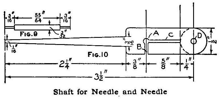
Shaft for Needle and Needle
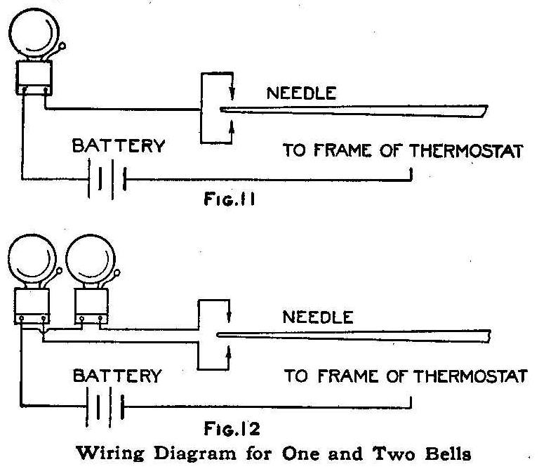
Wiring Diagram for One and Two Bells
The parts of the thermostat thus far made can now be assembled.
Place the steel shaft in its bearings and see that it turns
perfectly free. Then place the steel pin, on the end of the
couple, in the slot C, and fasten the other end of the couple, by
means of two machine screws, to the support made for the couple.
Increase or decrease the temperature of the thermostat and note
the results. If everything is working all right, the end of the
needle should move when the temperature of the thermostat is
changed. The amount the end of the needle moves can be easily
changed by moving the support or the couple toward or away from
the shaft supporting the needle, which changes the position of
the steel pin in the slot C. The nearer the steel pin is to the
shaft supporting the needle, the greater the movement of the end
of the needle due to a given change in temperature.
A small piece of white cardboard can be mounted directly under
the end of the needle by means of small brass strips, that in
turn can be attached to the lower ends of the main mounting holes
D, Fig. 4. A scale can be marked on this piece of cardboard by
noting the position of the needle corresponding to different
temperatures as determined by a thermometer. When this scale has
been completed, you can use the thermostat as a thermometer.
Two contacts may be mounted, one on each side of the needle, in a
manner similar to the method suggested for mounting the
cardboard. These contacts should be so constructed that the end
of the needle will slide over them with little friction, and so
that their position with respect to the end of the needle may be
easily changed. Both contacts must be insulated from the
remainder of the thermostat, and may or may not be connected
together, depending on how the thermostat is to be used.
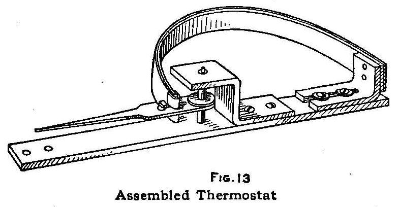
Assembled Thermostat
It would be advisable, if possible, to have the part of the
needle that touches the contact points, as well as these points,
of platinum, as the arc that is likely to be formed will not
destroy the platinum as easily as it will the brass. A small
wooden containing case can now be made and the thermostat is
complete. There should be a large number of holes drilled in the
sides, ends and back of the case so that the air inside may be
always of the same temperature as the outside air.
In adjusting, testing, or calibrating your thermostat, make sure
that it is in the same position that it will be in when in use.
The connections of the thermostat for ringing one bell when the
temperature rises or falls to a certain value, are shown in Fig.
11. The connections of the thermostat for ringing one bell when
the temperature rises to a certain value and another bell when
the temperature falls to a certain value, are shown in Fig. 12.
The complete thermostat is shown in Fig. 13.
A Tailless Kite
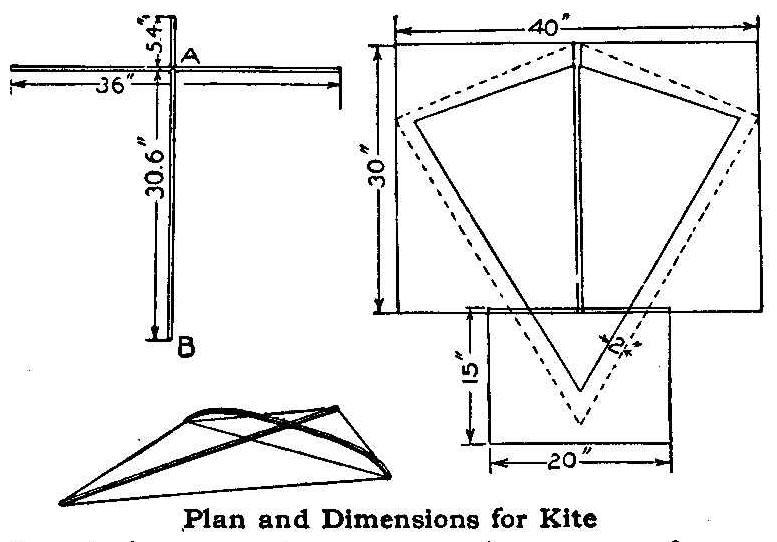
Plan and Dimensions for Kite
The frame of a 3-ft. kite is made of two sticks, each 3 ft. long.
These are tied together so that the cross stick will be at a
distance of 15 per cent of the full length of the upright stick,
from its end, or in this case 5.4 in. The sticks may be made of
straight grained pine, 3/8 in. square, for small kites, and
larger hardwood sticks, for larger kites.
The cross stick is bent into a bow by tying a strong cord across
from end to end. The center of the bend should be 4-1/2 in. above
the ends. The bend is shown in the sketch. Connect all four ends
or points with a cord, being careful not to pull the bend of the
cross stick down, but seeing that it remains straight across the
kite. When this is done the frame is ready for the cover.
The cover will require 2-1/2 sheets of tissue paper, 20 by 30
in., which should be pasted together as the sketch indicates. Cut
out the paper, allowing 2 in. margin for lapping over the cord on
the frame. Place the frame on the cover with the convex side
toward the paper and paste the margin over the cord, allowing the
paper to bag a little to form pockets for the air to lift the
kite. The corners should be reinforced with circular pieces of
paper pasted over the ends of the sticks.
The flying cord is attached to the points A and B of the frame.
There is no cross cord. The kite will fly at right angles to the
flying cord. It is easily started flying from the ground by
laying it with the head toward the operator and pulling it up
into the wind.
Contributed by Chas. B. Damik, Cooperstown, N. Y.
The Levitation—A Modern Stage Trick
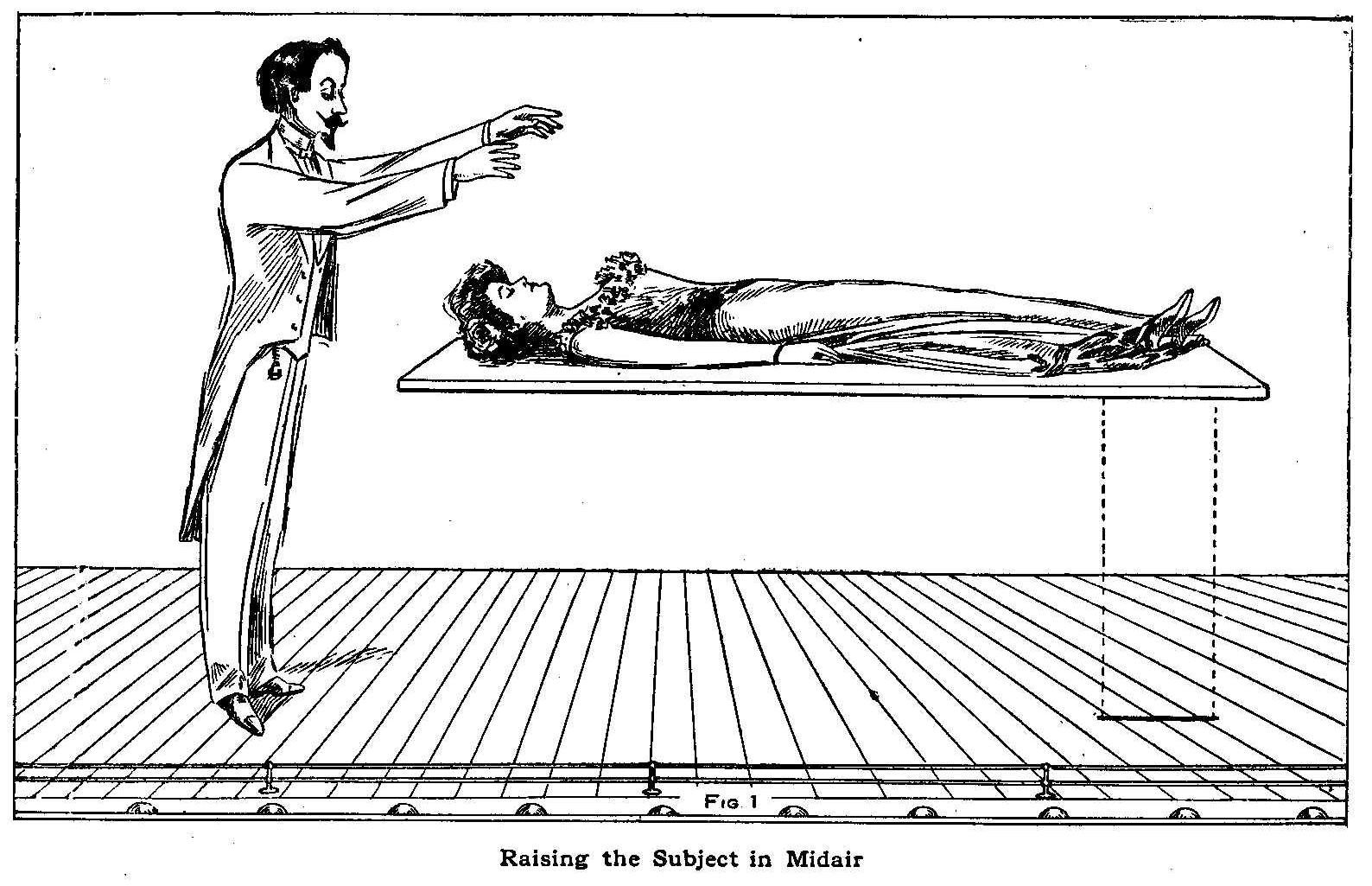
Raising the Subject in Midair
This illusion has mystified thousands of the theater-going
public, in fact, it has been the “piece de resistance” of many
illusion acts. The ordinary method of procedure is as follows:
The person who is to be suspended in the air, apparently with no
support—usually a lady—is first put in a hypnotic (?) sleep.
She is placed on a couch in the middle of the stage, and in most
cases the spotlight is brought into play. The performer then
takes a position close to the couch and with dramatic effect
makes a few hypnotic passes over the subject. She then slowly
rises from the couch until she has attained a height varying from
4 to 5 ft. above the stage, as shown in Fig. 1. The couch is then
taken a way and a hoop is passed over the floating lady. The
performer now causes the lady to float back to the couch or board
that she may have been resting on, after which the so-called
hypnotic spell is withdrawn.
In spite of the claims that the illusion owes its origin to
Hindoo magic, it is nothing more nor less than a clever
mechanical contrivance, the construction of which will be readily
understood by a glance at the accompanying illustrations.
The bottom of the couch, if one is used, contains a cradle-like
arrangement which fits the recumbent form of the lady and is
connected to a heavy sheet of plate glass by means of a rod, D,
Fig. 2, attached to one end, and running parallel to the side of
the cradle. When the glass is lifted, the body of the subject is
also raised, seemingly at the will of the performer. This is
accomplished by the aid of an assistant beneath the stage floor.
The plate of glass, E, Fig. 3, passes perpendicularly through the
stage down to a double block and tackle. The end of the cable is
attached to a drum or windlass and the plate glass held steady
with guides at the sides of the slot in the stage floor, through
which it passes. The winding up of the cable naturally forces the
plate glass and cradle up, causing the lady to rise.
Some illusionists place the lady on a board on two ordinary
trestles and cause the board to rise with the lady on it, as
shown in the illustration, thus obviating the use of heavy
paraphernalia as in the cradle attachment. The cradle attachment
is also generally accompanied by a 2-in. iron bar, used in the
place of the plate glass, the performer or operator standing at
the rear of the couch to conceal the bar as it comes from beneath
the stage. However, the method illustrated is the one generally
used.
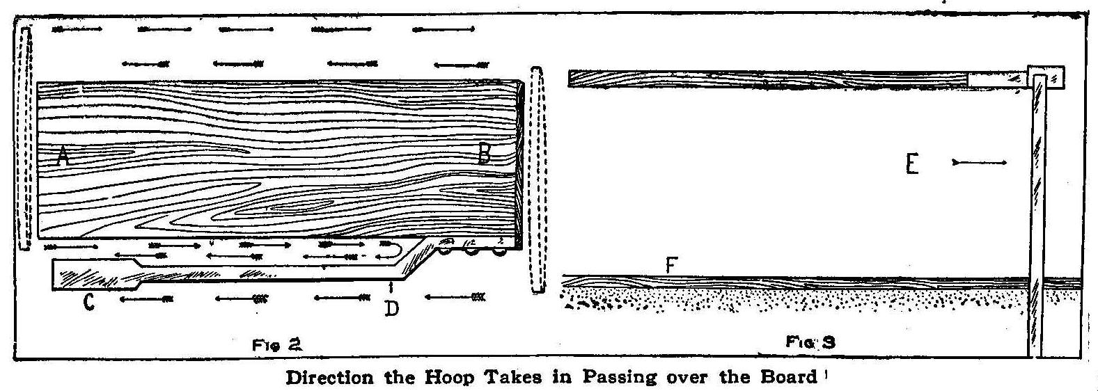
Direction the Hoop Takes In Passing over the Board
The solid hoop is passed over the body in the following manner:
Start at the end, B, Fig. 2, passing the hoop as far as C with
the hoop on the outside of the back horizontal rod. The side of
the hoop toward the audience is then turned and swung clear
around over the feet at A and entered between the rod and board
on which the lady rests. The hoop is then carried as far as it
will go back toward the end B. Then the side nearest the operator
is passed over the head of the body apparently the second time
and passed off free at the feet. Thus to the closest observer the
impression is given that the hoop has encircled the lady twice.
The illustrations give in detail the working of the illusion
above the stage floor. No set rule is used for the tackle and
drum below the floor.
Contents
The links below land on the page number at the top of the page.
Scroll down if the desired article is not visible.
| Accelerometer, Simple | 93 |
| Acid Burns, Treating | 126 |
| Acetylene Gas Generator, Homemade | 57 |
| Acetylene Lamp, Lighting | 401 |
| Aerating Water in a Small Tank | 241 |
| Aeroplane, Paper, How to Make | 329 |
| Aeroplanes, Model, Equilibrator for | 11 |
| Alarm, Burglar, How to Make | 368 |
| Alarm, Callers’ Approach | 87 |
| Alarm Clock Chicken Feeder | 79 |
| Alarm Clock to Pull Up Furnace Draft | 107 |
| Alarm, Electric | 94 |
| Alarm, Electric, Door Bell and | 114 |
| Alarm, Electric Fire, How to Make | 430 |
| Alarm, Electric, That Rings Bell and Turns On Light | 337 |
| Alarm, Electric Time | 433 |
| Alarm, Fire | 47, 359 |
| Aluminum Polish | 428 |
| Aluminum, Satin Finish on | 198 |
| Aluminum Wire, Insulating | 306 |
| Ammeter, How to Make | 49, 203 |
| Amusement-Boys Representing the Centaur | 173 |
| Amusement Device—Merry-Go-Round Thriller | 209 |
| Amusement Device—Merry-Go-Round, To Build | 359 |
| Amusement Device—Teeter Board, Revolving | 297 |
| Anesthesia, Electric | 445 |
| Animals, Small, Trap for | 82 |
| Annealing Chisel Steel | 362 |
| Annunciator, How to Construct | 57, 416 |
| Aquarium, How to Make | 64, 210 |
| Arbor, Grape, How to Build | 73 |
| Arc Lamp, Homemade | 132 |
| Arc Searchlight, Self Lighting | 9 |
| Arms and Armor, Imitation: | |
| Part I | 235 |
| Part II | 242 |
| Part III | 248 |
| Part IV | 263 |
| Part V | 271 |
| Part VI | 279 |
| Part VII | 284 |
| Arms, Drip Shield for | 258 |
| Arrowhead, Flint, How to Make | 23 |
| Asbestos Table Pads, Homemade | 212 |
| Athletes, Weights for, How to Make | 274 |
| Atomizer, How to Make | 158 |
| Automobile, Boys’ Homemade | 402, 430 |
| Automobile Engine, Cooling Water for | 236 |
| Automobile, Greasing the Front Wheels of | 320 |
| Automobile Headlights, Adjusting | 217 |
| Automobile, Painting | 357 |
| Automobile with Sails | 326 |
| Axle, Cart without | 291 |
| B | |
| Babbitt Ladle, Emergency | 264 |
| Babbitt, Ladle for Melting | 173 |
| Bag, Changing, for Plate Holders | 212 |
| Bag, Sewing, How to Make | 386 |
| Bags, Paper, Use for | 19 |
| Balloon Ascension Illusion | 300 |
| Balloon, Pilot, How to Make | 118 |
| Balloons, Paper, How to Make | 215 |
| Barometer, Homemade | 151 |
| Barometer, How to Make | 188 |
| Barrel Stave Hammock | 75 |
| Barrel Stave Sled | 383 |
| Baseball, Playing with a Pocket Knife | 250 |
| Baseball Throwing Practice, Device for | 312 |
| Bath, Shower, To Make | 15 |
| Bathtub Stopper, Substitute | 429 |
| Batteries, Connecting Up to Give Any Voltage | 93 |
| Batteries, Dry, To Obtain Cheaply | 410 |
| Batteries, Dry, To Renew | 369, 378, 401 |
| Batteries, Gravity, Why Fail | 115 |
| Battery Binding Posts, Wire Loop Connections for | 449 |
| Battery Cell, Dry, Making | 160 |
| Battery Connections, Wire Terminals for | 168 |
| Battery, Grenet, How to Make | 83 |
| Battery Motor, Controller and Reverse for | 72 |
| Battery Motor, Reversing | 405 |
| Battery, Non-Polarizing, How to Make | 151 |
| Battery Rheostat | 80, 445 |
| Battery, Small Storage, How to Make | 121 |
| Battery Switch | 99 |
| Battery, Thermo-Electric, How to Make | 59, 140 |
| Battery Voltmeter | 153 |
| Battery Zincs, Old, To Use | 87 |
| Bed Warmer, Electric, How to Make | 338 |
| Beeswax, Substitute for | 129 |
| Bell, Cracked, Restoring Tone to | 71 |
| Bell, Return Call, with One Wire | 101 |
| Bell Ring Register | 316 |
| Bell, Ringing by Touching a Gas Jet | 403 |
| Belt, Eyelets for | 432 |
| Belt Lace Caution | 239 |
| Belt, Round, To Make without Ends | 243 |
| Bench Lathe Made of Pipe Fittings | 316 |
| Bicycle Catamaran | 145 |
| Bicycle Coasting Sled, How to Make | 231 |
| Bicycle Frame, Enameling | 385 |
| Bicycle, Runners on | 157 |
| Bicycle, To Attach a Sail to | 425 |
| Bicycle, Trailer for | 397 |
| Bicycle Trouser Guards for Sleeve Bands | 283 |
| Bicycle, Water, How to Make | 335 |
| Bill File Made of Corkscrews | 315 |
| Bind Magazines, To | 40, 56, 406 |
| Bird House, Proper Design for | 201 |
| Bird Houses, Clay Flower Pots Used for | 277 |
| Bit, Gouge Used as | 411 |
| Blotter Pad, Corner Pieces for | 8 |
| Blotting Pad, Desk | 17 |
| Blowpipe, Homemade | 428 |
| Blueprint Lantern Slides, How to Make | 120 |
| Blues, Prussian and Chinese | 401 |
| Boards, Joining | 268 |
| Boat-Bicycle Catamaran | 145 |
| Boat-Canoe, How to Make | 451 |
| Boat-Catamaran, Cruising | 423 |
| Boat, Ice, How to Build | 357, 382 |
| Boat, Paddle, How to Make | 100 |
| Boat, Paper, How to Make | 321 |
| Boat-Punt, Homemade | 123 |
| Bobsled, Homemade Yankee | 408 |
| Bolts, Rusted | 151 |
| Book Cover, Paper, How to Make | 126 |
| Book Holder | 32 |
| Book, Removing Grease Stains from | 230 |
| Book Rest | 292 |
| Bookcase Doors, To Keep Closed | 377 |
| Bookmark | 379 |
| Bookmark, Brass | 18 |
| Bookmark, Paper Clip | 241 |
| Books, How to Carry | 409 |
| Boomerangs, How to Make | 4, 202 |
| Bore a Square Hole, How to | 179 |
| Boring Holes In Cork | 8 |
| Bottle, Cutting Thread inside of | 179 |
| Bottle, Diving | 331 |
| Bottle, Inverted, Withdrawing Paper from Under | 33 |
| Bottle, Photographing Man in | 74 |
| Bottle Pushing on the Ice | 409 |
| Bottles, Round End, Base for | 29 |
| Bottle Stopper, New Way to Remove | 224 |
| Bowl, Copper, How to Make | 185 |
| Box Cover, Sliding, Fastener | 256 |
| Box, Fishhook | 379 |
| Box, Magic | 7 |
| Box, Water Color | 257 |
| Boxes, Rustic Window | 30 |
| Bracket Saw, Cheap, How to Make | 42 |
| Brass Bookmark | 18 |
| Brass, Cleaning | 407 |
| Brass Flag, Ornamental, How to Make | 266 |
| Brass Frame In Repoussé | 237 |
| Brass Furnace, How to Build | 115 |
| Brass, Piercing Punch for | 19 |
| Brass Plaques, Photo Silhouette, Making | 217 |
| Brass Surface, Flat, Polishing | 229 |
| Brass Work-Candlestick, How to Make | 325 |
| Bread, Loaf, Cutting | 36 |
| Bronze Liquid | 329 |
| Brooder for Small Chickens | 343 |
| Broom Holder | 13 |
| Broom Holder Made of a Hinge | 33 |
| Broom, Old, Crutch Made of | 352 |
| Brush, Counter, for a Shop | 419 |
| Brush, To Keep from Spreading | 367 |
| Brushes, Paint, Care of | 267 |
| Bulb on a Glass Tube, To Make | 324 |
| Bunsen Cell, How to Make | 206 |
| Burglar Alarm, Simple, How to Make | 368 |
| Burning Inscriptions on Trees | 45 |
| Burns, Carbolic Acid | 126 |
| Button, Changing into a Coin | 234 |
| Button, Removing from Child’s Nostril | 237 |
| Buttonhole Trick | 234 |
| C | |
| Cabinet for Pot Covers | 16 |
| Cabinet for Phonograph Records | 433 |
| Cabinet, Music, How to Make | 77 |
| Cabinet, Phonograph Disk Cabinet | 79, 433 |
| Calendar, Handy | 196 |
| Calliope, Steam, How to Make | 418 |
| Camera, Box, Repairing | 379 |
| Camera, Enlarging from Life in | 111, 117 |
| Camera, Homemade Kits for | 159 |
| Camera, Making Light proof | 58 |
| Camera, Practical, for Fifty Cents | 365 |
| Camp Stool, How to Make | 222 |
| Camp, Tin Drinking Cup for | 379 |
| Camper’s Lantern, Makeshift | 266 |
| Camps and How to Build Them | 341 |
| Camps, Keeping Food Cool in | 21 |
| Can Covers, Tool for Lifting | 352 |
| Candle Shade, How to Make | 191 |
| Candlestick, How to Make | 240, 281, 325 |
| Candlestick, Water | 406 |
| Cane Chairs, How to | 259 |
| Cane in Furniture, Tightening | 230 |
| Cannon Balls, 36, Removing from Handbag | 256 |
| Cannon, Gas | 197 |
| Cannon, How to Make | 42 |
| Cannon, Lead, How to Make | 338 |
| Cannon, Toy, To Discharge by Electricity | 59 |
| Canoe, How to Make | 451 |
| Canoe, Sailing, How to Make | 199 |
| Cans, Tomato, Irrigating with | 450 |
| Canvas Cot, Folding, How to Make | 154 |
| Canvas, Waterproofing | 146 |
| Carburetor Difficulties | 208 |
| Card Trick, Rising | 256 |
| Card Trick with a Tapered Deck | 70 |
| Cardboard Spiral Turned by Heat | 226 |
| Cardboard Squares, Gun for Throwing | 269 |
| Cardcase, Lady’s, How to Make | 350 |
| Cards, Mechanical Trick with | 63 |
| Carpenter’s Gauge | 19 |
| Carpenter’s Vise, Homemade | 36 |
| Carpet Sweeper Wheels, New Tires for | 266 |
| Cart, Dog | 60 |
| Cart without an Axle | 291 |
| Catamaran, Bicycle | 145 |
| Catamaran, Cruising | 423 |
| Catapult, Fourth of July | 447 |
| Cats, Shocking, Device for | 411 |
| Cell, Bunsen | 206 |
| Cell, Daniell | 252 |
| Centaur, Boys Representing | 173 |
| Centering, To Make Unnecessary | 319 |
| Chain Made from a Match | 377 |
| Chair, Child’s Footrest on | 453 |
| Chair Legs, Rubber Tip for | 229 |
| Chair, Porch Swing | 128 |
| Chair Rockers, Safety Tips on | 429 |
| Chair Sleighs | 383 |
| Chairs, Balancing on | 131 |
| Chairs, To Cane | 259 |
| Checker Board Puzzle | 189, 233 |
| Cheese box Cover, Tea Tray | 18 |
| Chemicals, Protecting Fingers from | 283 |
| Cherry Seeder | 29 |
| Chicken Coop, Keeping Rats from | 352 |
| Chickens, Drinking Trough for | 454 |
| Chickens, Feed Box for | 292 |
| Chickens, Small, Brooder for | 343 |
| Chisel, Ice | 61 |
| Chisel, Steel, Annealing | 362 |
| Chopping Board | 19 |
| Christmas Tree Decorations, Repairing | 11 |
| Churn, Homemade Small | 192 |
| Clamp, Magazine, How to Make | 435 |
| Clamping a Cork | 33 |
| Clamps, Homemade Soldering: | 137 |
| Cleaner for Gloves | 302 |
| Cleaner for White Shoes | 239 |
| Cleaning Brass | 407 |
| Cleaning Discolored Silver | 344 |
| Cleaning Furniture | 185 |
| Cleaning, Glass, Solution | 31 |
| Cleaning Jewelry | 353 |
| Cleaning Leather on Furniture | 13 |
| Cleaning Silver | 305 |
| Cleaning Walls | 375 |
| Cleaning Woodwork | 315 |
| Cleats, Insulating, Substitute for | 348 |
| Clock, Electric, How to Make | 268 |
| Clock, Homemade Novelty | 446 |
| Clock, How to Clean | 119 |
| Clock, Novelty, for the Kitchen | 360 |
| Clock, Old, Use for | 367 |
| Clothes Rack | 14 |
| Clothesline, Double, Support for | 318 |
| Coaster, Roller, Illusion | 293 |
| Coaster, Trolley, How to Make | 387 |
| Coasters and Chair Sleighs | 383 |
| Cock, Three Way, for Small Model Work | 50 |
| Coil, Jump Spark | 113 |
| Coils, Forming to Make Flexible Wire Connections | 443 |
| Coin and Card on the First Finger | 175 |
| Coin and Tumbler Trick | 378 |
| Coin, Changing Button Into | 234 |
| Coin, Disappearing | 176, 193 |
| Coin In a Wine Glass Trick | 167 |
| Coin, Moving under a Glass | 214 |
| Coin Purse, How to Make | 354 |
| Coin, Sticking against Wall | 176 |
| Coin, Sticking to Wood by Vacuum | 287 |
| Coins, Display Rack Shows Both Sides of | 220 |
| Coins, Sending by Mail, Safe Method of | 287 |
| Compass, Mariner’s | 170 |
| Compass Needle, Floating | 160 |
| Compass, Substitute for | 289 |
| Compressed Air Phenomenon | 111 |
| Concrete Kennel | 23 |
| Concrete Swimming Pool | 178 |
| Conservatory, Window | 103 |
| Controller for a Small Motor | 42 |
| Cook Fish, One Way to | 206 |
| Copper Bowl, How to Make | 185 |
| Copper, Hardening | 206 |
| Copper Picture Frame, Etched, How to Make | 414 |
| Copper Trays, How to Make | 180 |
| Copper Work—Corner Pieces for a Blotter Pad | 8 |
| Cord, Buttoned | 427 |
| Cork, Boring, Holes in | 8 |
| Cork, Clamping | 33 |
| Cork Extractor | 300 |
| Corks, How to Fit | 368 |
| Corkscrews, Bill File Made of | 315 |
| Corner Pieces for a Blotter Pad, How to Make | 8 |
| Cot, Canvas, How to Make | 154 |
| Counter Brush for a Shop | 419 |
| Crossbow and Arrow Sling, How to Make | 339 |
| Crutch, Homemade | 369 |
| Crutch Made of an Old Broom | 352 |
| Crystallization, Instantaneous | 288 |
| Cup and Saucer Rack, How to Make | 105 |
| Cup, Tin Drinking, for the Camp | 379 |
| Current Reverser | 107, 111 |
| Curtain Roller | 419 |
| Curtain Roller Spring, How to Tighten | 79 |
| D | |
| Dance, Miniature War | 255 |
| Darkroom Lantern, Homemade | 14, 340 |
| Darkroom, Photographic, Building | 26 |
| Demagenetizing a Watch | 166 |
| Desk Blotting Pad | 17 |
| Developing Box, How to Make | 220 |
| Developing Tray, Cracked Composition, To Repair | 260 |
| Developing Tray, Photographic | 269 |
| Dish Holder, Hot | 7 |
| Dogcart, Homemade | 160 |
| Dog, How to Chain | 257 |
| Dog’s Bark, Drowning with Water | 435 |
| Dogs, To Drive Away | 106 |
| Door Bell and Electric Alarm | 114 |
| Door Lock, Secret | 6 |
| Door Opener, Electric | 78 |
| Door Opener for a Furnace | 83 |
| Door, Sliding, Electric Lock for | 89 |
| Dovetail Joint | 29 |
| Dovetail Joint Puzzle | 236 |
| Draft Opener, Automatic | 102 |
| Draftsman, Spline for | 406 |
| Draftsman’s Ink Bottle Cork, Steel Pen Used In | 117 |
| Drawers, Several, Locking with One Lock | 314 |
| Drawing, Aid In | 270 |
| Drawing Instrument-Wondergraph, How to Make | 436 |
| Drawing, Landscape, Made Easy | 449 |
| Drill Gauge, Handy | 252 |
| Drill, Hand, How to Make | 444 |
| Drinking Cup, Tin, for the Camp | 379 |
| Drinking Trough for Chickens | 454 |
| Drip Shield for the Arms | 258 |
| Dry Batteries, Another Way to Renew | 378 |
| Dry Batteries, Cheap, How to Obtain | 410 |
| Dry Batteries, Old, To Renew | 401 |
| Dry Batteries, Renewing | 367 |
| Dry Battery Cell, How to Make | 160 |
| Duplicator for Box Cameras | 363 |
| Duplicator, Homemade | 240 |
| E | |
| Easel, How to Make | 415 |
| Egg-Beater, How to Make | 291 |
| Eggshell Funnel | 93 |
| Eggshells, How to Preserve | 288 |
| Elderberry Huller, Homemade | 323 |
| Electric Alarm | 94 |
| Electric Alarm, Door Bell and | 114 |
| Electric Alarm That Rings a Bell and Turns On a Light | 337 |
| Electric Anesthesia | 445 |
| Electric Apparatus-Ammeter, How to Make | 49, 203 |
| Electric Apparatus-Annunciator, Homemade | 57 |
| Electric Apparatus-Annunciator, How to Construct | 416 |
| Electric Apparatus-Batteries, Connecting Up to Given Any Voltage | 93 |
| Electric Apparatus-Battery Rheostat | 80 |
| Electric Apparatus-Battery Voltmeter | 153 |
| Electric Apparatus-Bell, Return Call, with One Wire | 101 |
| Electric Apparatus-Cats, To Shock | 411 |
| Electric Apparatus-Cell, Daniell | 252 |
| Electric Apparatus-Circuit Breaker for Induction Coils | 101 |
| Electric Apparatus-Controller and Reverse for Battery Motor | 72 |
| Electric Apparatus-Controller for a Small Motor | 42 |
| Electric Apparatus-Current Reverser | 107, 111 |
| Electric Apparatus-Galvanometer, Tangent | 150 |
| Electric Apparatus-Induction Coil, How to Make | 138 |
| Electric Apparatus-Induction Coils, Mercury | |
| Make and Break Connection for | 187 |
| Electric Apparatus-Jump Spark Coil | 113 |
| Electric Apparatus-Medical Induction Coil, How to Make | 63 |
| Electric Apparatus-Motor, Single Phase Induction | 124 |
| Electric Apparatus-Motors, Direct Connected Reverse for | 60 |
| Electric Apparatus-Rheostat, Lead Pencil | 145 |
| Electric Apparatus-Shocking Machine | 139 |
| Electric Apparatus-Thermo Battery, How to Make | 59 |
| Electric Apparatus-Thermostat, Small | 455 |
| Electric Apparatus-Transformer, 110-Volt | 439 |
| Electric Apparatus-Voltammeter, Pocket | 330 |
| Electric Battery Massage, Homemade | 144 |
| Electric Bed Warmer, Homemade | 338 |
| Electric Bell, Relay Made from | 94 |
| Electric Blue Light Experiment | 47 |
| Electric Clock, Homemade | 268 |
| Electric Charges, Detector for | 281 |
| Electric Door Opener | 78 |
| Electric Engine | 276 |
| Electric Experiment, Interesting | 377 |
| Electric Experiment, Reversing Switch for | 92 |
| Electric Fire Alarm, How to Make | 430 |
| Electric Furnace Regulator, How to Make | 388 |
| Electric Furnace, Small, How to Make | 48 |
| Electric Heat Regulator, Automatic | 344 |
| Electric Horn, How to Make | 218 |
| Electric Hydrogen Generator | 54 |
| Electric Illusion Box | 135 |
| Electric Indicator for a Wind Vane | 348 |
| Electric Lamp Experiment | 53, 120, 131 |
| Electric Lamp Sockets, Miniature, How to Make | 270 |
| Electric Lamps, Miniature | 434 |
| Electric Lamps, Testing | 314 |
| Electric Light Circuit, Experiments with | 50 |
| Electric Lighting, Miniature | 104 |
| Electric Lights, Turned On and off from Different Places | 205 |
| Electric Lock | 60, 110 |
| Electric Lock for Sliding Door | 89 |
| Electric Lock, Simple | 60 |
| Electric Locomotive, Miniature, How to Make | 165 |
| Electric Motor | 401 |
| Electric Motor, Novel | 395 |
| Electric Motor, Small | 214, 222, 345 |
| Electric Pendant Switch, How to Make | 310 |
| Electric Piano, How to Make | 247 |
| Electric Plug, Homemade | 430 |
| Electric Postcard Projector | 195 |
| Electric Rat Exterminator | 358 |
| Electric Shock, To Give While Shaking Hands | 133 |
| Electric Shocker for Garbage Cans | 94 |
| Electric Stove, Homemade | 31, 273 |
| Electric Terminals, Varnish for | 376 |
| Electric Time Alarm | 433 |
| Electric Toaster, How to Make | 37 |
| Electric Walking Stick | 413 |
| Electric Wires, Flexible, Adjuster for | 386 |
| Electricity, To Discharge Toy Cannon by | 59 |
| Electricity; To Explode Powder with | 53 |
| Electricity, Writing with | 74 |
| Electrodeposition, Copies Made from Wax Molds by | 157 |
| Electrolytic Rectifier, How to Make | 197 |
| Electromagnet, Floating | 152 |
| Electroplating, Easy Method of | 88 |
| Electroscope, How to Make | 103 |
| Electrostatic Illumination | 299 |
| Emery Wheel Arbors, Washers for | 359 |
| Enameling a Bicycle Frame | 385 |
| Engine, Electric | 276 |
| Engine, Gasoline, How to Make | 207 |
| Engine, Model Steam | 1 |
| Engine, Steam, Made from Gas Pipe and Fittings | 184 |
| Engine, Toy Steam, How to Make | 73 |
| Engine, Turbine, How to Make | 355 |
| Equatorial, Homemade | 204, 253 |
| Equilibrator for Model Aeroplanes | 11 |
| Experiment, Center of Gravity | 302 |
| Experiment, Electric | 377 |
| Experiment, Electric Blue Light | 47 |
| Experiment, Heat and Expansion | 124 |
| Experiment, Phonograph | 105 |
| Experiment, Telephone | 137 |
| Experiment with a Vacuum | 439 |
| Experiment with Colored Electric Lamps | 53 |
| Experiment with Heat | 134 |
| Experiment with Incandescent Lamp | 427 |
| Experiment with Two Foot Rule and Hammer | 106 |
| Experiment, X-Ray | 190 |
| Experiments, Electric Lamp | 120, 131 |
| Experiments, Electrical, Reversing Switch for | 92 |
| Experiments with a Mirror | 434 |
| Experiments with Electric Light Circuit | 50 |
| Eye, Blind Spot in, To Find | 129 |
| Eyeglasses, Holding Firm | 315 |
| F | |
| Fan, Wooden, How to Make | 332 |
| Faucet Used as an Emergency Plug | 343 |
| Feed Box for Chickens | 292 |
| File, Chalking | 19 |
| File, Sharpening Skates with | 306 |
| File Soft Metals, How to | 406 |
| Film Washing Trough | 331 |
| Films, Drying | 412 |
| Films, Frame for Drying | 446 |
| Filter, Simple and Effective | 278 |
| Filtering with a Small Funnel | 25 |
| Finger Mathematics | 181 |
| Finger, Removing Tight Fitting Ring from | 361 |
| Fingers, Protecting from Chemicals | 283 |
| Fire Alarm, Cheap | 47 |
| Fire Alarm, Electric, How to Make | 430 |
| Fire Alarm, Simple, How to Make | 359 |
| Fire Extinguisher, Homemade | 351 |
| Fire, Making with the Aid of Ice | 338 |
| Fire Screen, How to Make | 82 |
| Fire Screen, Leaded Glass | 295 |
| Fish Bait | 152 |
| Fish, One Way to Cook | 206 |
| Fishhook Box | 379 |
| Fishing through Ice, Signals for | 10, 281, 380 |
| Flag, Brass, How to Make | 266 |
| Flatiron Rest | 19 |
| Flier, Toy, How to Make | 429 |
| Flint Arrowhead, How to Make | 23 |
| Floor Polisher, Homemade | 10, 350 |
| Flour Sifter | 7 |
| Flower, Magic Growing | 244 |
| Flower Pot Stand | 33 |
| Flower Pots, Clay, Used for Bird Houses | 277 |
| Flower Pots, Window Shelf for | 292 |
| Flower Stand, Iron | 353 |
| Flowers, Cut, To Longer Preserve | 419 |
| Flowers, Decoloration of | 288 |
| Flush Valve, Repairing a Washer on | 344 |
| Fob, Shoestring Watch, How to Weave | 285 |
| Fob, Watch, How to Make | 12, 223 |
| Food, Keeping Cool in Camps | 21 |
| Football, Tying Knot for | 133 |
| Footrest, Child’s, on an Ordinary Chair | 453 |
| Footwear, Drier for | 229 |
| Forks, Balancing on a Pin Head | 427 |
| Foundry Work at Home | 95 |
| Fountain for an Ordinary Pen | 450 |
| Fountain Pen, Ordinary Pen Used as | 454 |
| Fountain Pen Used as a Ruler | 319 |
| Fountain Pens, Leaking, Remedy for | 390 |
| Frame, Brass, in Repoussé | 237 |
| Frost, To Keep Windows Free from | 354 |
| Fuming of Oak | 196 |
| Funnel, Eggshell | 93 |
| Funnel, Filtering with | 25 |
| Funnel, Glass | 412 |
| Funnel, Horn Used as | 7 |
| Funnel, Temporary | 275 |
| Funnel, Venting a | 318 |
| Furnace, Brass, How to Build | 115 |
| Furnace, Door Opener for | 83 |
| Furnace Draft, Alarm Clock to Pull Up | 107 |
| Furnace Draft Opener, Automatic | 102 |
| Furnace, Electric, How to Make | 48 |
| Furnace Regulator, Electric, How to Make | 388 |
| Furniture, Cleaning | 185 |
| Furniture, Cleaning Leather on | 13 |
| Furniture, Drawing of | 294 |
| Furniture—Library Set in Pyro-Carving | 407 |
| Furniture—Rustic Seat | 441 |
| Furniture—Table, Mission Library, How to Make | 141 |
| Furniture, Tightening Cane In | 230 |
| G | |
| Galvanometer, Tangent, How to Make | 150 |
| Galvanoscope, How to Make | 68 |
| Game-Baseball, Playing with a Pocket Knife | 250 |
| Game-Bottle Pushers | 409 |
| Game, Chinese Outdoor | 176 |
| Game Played on the Ice | 216 |
| Garbage Can, Keeping Animals Away from | 94 |
| Gas Cannon | 197 |
| Gas Jet, Ringing a Bell by Touching | 403 |
| Gas Jet, Shade Holder Bracket for | 419 |
| Gas, To Light without Matches | 394 |
| Gasoline Burner for Model Work | 55 |
| Gasoline Engine, Homemade | 207 |
| Gauge, Carpenter’s | 19 |
| Gauge, Drill | 252 |
| Gauge, Rain, How to Make | 64 |
| Gauntlets on Gloves | 266 |
| Gear Cutting Attachment for Small Lathes | 167 |
| Gear for Model Work | 225 |
| Gear Wheels, Small, To Make without a Lathe | 46 |
| Geissler Tube, How to Make | 154 |
| Glass Blowing and Forming | 420 |
| Glass Cleaning Solution | 31 |
| Glass, Effect of Radium on | 116 |
| Glass, Emergency Magnifying | 305 |
| Glass, Fire Screen, Leaded | 295 |
| Glass Funnel, Emergency | 412 |
| Glass, Ground, Imitating | 294 |
| Glass, Ground, Substitute | 255 |
| Glass Letters, Removing from Windows | 319 |
| Glass, Magnifying, How to Make | 397 |
| Glass, Photograph Prints Mounted on | 231 |
| Glass Plates, Piercing with a Spark Coil | 426 |
| Glass Tube, To Make a Bulb on | 324 |
| Glider, How to Make | 171 |
| Gloves, Cleaner for | 302 |
| Gloves, Gauntlets on | 266 |
| Gold Leaf, Covering Signals with | 189 |
| Gouge Used as a Bit | 411 |
| Gramophone Records, Cracked, Repairing | 24 |
| Grape Arbor, How to Build | 73 |
| Gravity Batteries, Why Fail | 115 |
| Gravity Experiment | 302 |
| Grease Stains, Removing from Book | 230 |
| Grease, To Remove from Machinery | 216 |
| Greasing the Front Wheels of an Automobile | 320 |
| Grills, Rope, How to Make | 277 |
| Ground Glass, Imitating | 294 |
| Guitar That Is Easy to Make | 320 |
| Gummed Paper, Substitute for | 315 |
| Gun Barrels, Bursting of | 304 |
| Gun, Toy, for Throwing Cardboard Squares | 269 |
| Gymnasium, Outdoor: | |
| Part I-The Horizontal Bar | 298 |
| Part II~Parallel Bars | 301 |
| Part III-The Horse | 303 |
| H | |
| Hacksaw Blade, Knife Made from | 293 |
| Hammock, Barrel Stave | 75 |
| Hammock, How to Make | 410 |
| Hand Car Made of Pipe and Fittings | 440 |
| Hand, Magic Spirit | 2 |
| Handbag, Ladies’, How to Make | 213 |
| Handbag, Removing 36 Cannon Balls from | 256 |
| Handkerchief Mended after Being Cut and Torn | 198 |
| Handkerchief Trick, Vanishing | 319 |
| Handle, Opening, for a Stamp Pad | 23 |
| Handle, Tying Paper Bag to Make | 10 |
| Hanger, Trousers, How to Make | 143, 369 |
| Hangers, Tool | 453 |
| Hardening Copper | 206 |
| Harmonograph, Line | 34 |
| Hat, To Hang on a Lead Pencil | 133 |
| Hatpins, Sealing Wax, How to Make | 175 |
| Hats, Felt, Packing Cut from | 207 |
| Heat and Expansion | 124 |
| Heat, Cardboard Spiral Turned by | 226 |
| Heat, Experiment with | 134 |
| Heat Regulator, Electric | 344 |
| Hectograph, Homemade | 240, 326 |
| Hinge, Broom Holder Made of | 33 |
| Hinges, Imitation Fancy Wings on | 224 |
| Hinges, Leather, Metal Covering for | 41 |
| Hole, Square, How to Bore | 179 |
| Hole, Threaded, Sizing | 295 |
| Holes, Boring In Cork | 8 |
| Holes, Circular, Cutting In Thin Sheet Metal | 35 |
| Holes, Different Shaped, Fitting Plug in | 122 |
| Horn, Electric, How to Make | 218 |
| Horn, Paper Phonograph, How to Make | 71 |
| Horn Used as Funnel | 7 |
| Horsepower of Small Motors, Finding | 238 |
| House, Building In a Tree Top | 146 |
| Hydrogen Generator, Constant Pressure | 70 |
| Hydrogen Generator, Small Electrical | 54 |
| Hygrometer, How to Make | 71, 140 |
| I | |
| Ice Boat, How to Build | 357 |
| Ice Boating | 382 |
| Ice, Bottle Pushing on | 409 |
| Ice Chisel, Handy | 61 |
| Ice, Fish Signal for Fishing through | 10 |
| Ice, Fishing through | 281 |
| Ice, Game Played on | 216 |
| Ice, Making a Fire with the Aid of | 338 |
| Ice, Merry-Go-Round Whirl on | 380 |
| Ice, Peculiar Properties of | 100 |
| Ice, Signals for Fishing through | 380 |
| Ice Skates, Hollow Grinding | 231 |
| Ice Yacht, How to Build | 307 |
| Illusion, Balloon Ascension | 300 |
| Illusion Box, Electric | 135 |
| Illusion for Window Attraction | 239 |
| Illusion, Miniature “Pepper’s Ghost” | 52 |
| Illusion, Roller Coaster | 293 |
| Illusion, Rolling Uphill | 361 |
| Illusions, Optical | 74, 99, 130, 183, 206, 348, 364 |
| Incandescent Lamp, Experiment with | 427 |
| Indian Clubs, Weighting | 318 |
| Indicator, Electric, for a Wind Vane | 348 |
| Induction Call, How to Make | 138 |
| Induction Coil, Lighting an Incandescent Lamp with | 112 |
| Induction Call, Small Medical, How to Make | 63 |
| Induction Coils, Circuit Breaker for | 101 |
| Induction Calls, Mercury Make and Break Connections for | 187 |
| Induction Motor, Single Phase, How to Make | 124 |
| Ink Bottle Cork, Steel Pen Used in | 117 |
| Ink Spots, Removing | 131 |
| Inkstand, Ornamental Metal | 315 |
| Insulating Aluminum Wire | 306 |
| Insulating Cleats, Substitute for | 348 |
| Insulation, Removing from Wire | 213 |
| Interrupter, How to Make | 51 |
| Iodine Stains, Removing | 425 |
| Iron Castings, Putty for | 269 |
| Iron Flower Stand, Ornamental | 353 |
| Iron Polisher | 286 |
| Iron Rest for an Ironing Board | 288 |
| Iron Work, Ornamental, Easy Designs in | 370 |
| Ironing Board Stand, How to Make | 17, 429 |
| Irrigating with Tomato Cans | 450 |
| J | |
| Jelly Making Stand | 290 |
| Jewelry, How to Clean | 353 |
| Jig Saw Puzzle, Photographic | 361 |
| Joint, Dovetail | 29 |
| Jump Spark Coil, How to Make | 113 |
| K | |
| Kennel, Concrete | 23 |
| Kennel Door, Automatic Closing | 32 |
| Kerosene, Used in Polishing Metals | 364 |
| Kettle, Spoon holder On | 24 |
| Kettles, Spoon Rest for | 304 |
| Key Forms, Preserving | 454 |
| Key, Removing from a Double String | 179 |
| Kiln, Pottery | 62 |
| Kitchen, Novelty Clock for | 360 |
| Kitchen Utensil—Baking Pan | 13 |
| Kitchen Utensil—Cherry Seeder | 29 |
| Kitchen Utensil—Chopping Board | 19 |
| Kitchen Utensil—Egg-Beater, How to Make | 291 |
| Kitchen Utensil—Elderberry Huller | 323 |
| Kitchen Utensil—Flour Sifter | 7 |
| Kitchen Utensil for Removing Pies from Pans | 275 |
| Kitchen Utensil—Homemade Toaster | 139 |
| Kitchen Utensil—Hot Dish Holder | 7 |
| Kitchen Utensil—Hot Plate Lifter | 318 |
| Kitchen Utensil—Jelly Making Stand | 290 |
| Kitchen Utensil—Knife Sharpener | 379 |
| Kitchen Utensil—Ladle and Strainer, Combined | 302 |
| Kitchen Utensil—Pot Cover Closet | 16 |
| Kitchen Utensil—Pot Covers, Homemade | 297 |
| Kitchen Utensil—Querl, Versatile | 28 |
| Kitchen Utensil—Salad Dressing Mixer | 16 |
| Kitchen Utensil—Spoon Rest for Kettles | 24, 304 |
| Kitchen UtensilvTool for Lifting Can Covers | 352 |
| Kitchen Utensil—Vegetable Slicer | 413 |
| Kite Balancing Strings, Rubber Bands in | 270 |
| Kite, Box, How to Make | 58 |
| Kite, Chinese, How to Make and Fly | 210 |
| Kite Reel, Homemade | 156 |
| Kite, Tailless | 458 |
| Kites of Many Kinds and How to Make Them | 391 |
| Knife Blade, Worn, Repairing | 228 |
| Knife Made from Hacksaw Blade | 293 |
| Knife, Pocket, Playing Baseball with | 250 |
| Knife Sharpener, Kitchen | 379 |
| Knot, Magic | 198 |
| Knot Trick | 167 |
| Knot, Tying for Football | 133 |
| L | |
| Ladle and Strainer, Combined | 302 |
| Ladle, Babbitt | 264 |
| Ladle for Melting Babbitt | 173 |
| Lamp, Acetylene, Lighting | 401 |
| Lamp, Arc | 132 |
| Lamp Cord, Flexible, Holder for | 317 |
| Lamp Cords, Flexible, Clasp for Holding | 267 |
| Lamp, Flash, How to Make | 174 |
| Lamp, Homemade Pocket | 149 |
| Lamp, Incandescent, Experiment with | 427 |
| Lamp, Incandescent, Lighting with an Induction Coil | 112 |
| Lamp, Quickly Made | 329 |
| Lamp Sockets, Miniature Electric, How to Make | 270 |
| Lamp Stand and Shade, How to Make | 147 |
| Lamps, Electric, Testing | 314 |
| Lamps, Miniature Electric | 434 |
| Lamps, To Make Burn Brightly | 364 |
| Lantern, Camper’s Makeshift | 266 |
| Lantern, Darkroom, How to Make | 14, 340 |
| Lantern, Homemade | 163 |
| Lantern, Magic, How to Make | 328 |
| Lantern, Magic, Using Sun’s Light in | 251 |
| Lantern Slide Masks, Cutting | 245 |
| Lantern Slides, Blueprint, How to Make | 120 |
| Lantern Slides, How to Make | 127, 220 |
| Lantern Slides, Tinted, How to Make | 144 |
| Lathe, Bench, Made of Pipe Fittings | 316 |
| Lathe, How to Make | 86 |
| Lathe, Making Gear Wheels without | 46 |
| Lathe, Wood Turning, To Make Out of an Old Sewing Machine | 403 |
| Lathe Work, Calipering | 258 |
| Lathes, Small, Gear Cutting Attachment for | 167 |
| Laundry Device—Clothes Rack | 14 |
| Laundry Device—Clothesline, Double, Support for | 318 |
| Laundry Device—Iron Rest | 19 |
| Laundry Device—Iron Rest for an Ironing Board | 288 |
| Laundry Device—Ironing Board Stand | 17, 429 |
| Laundry Device—Sad Iron Polisher | 286 |
| Laundry Device—Washboard Holder | 39 |
| Lavatories, Sleeve Holders for | 17 |
| Lead Cannon, How to Make | 338 |
| Lead, Melting in Tissue Paper | 185 |
| Lead Pencil Rheostat, How to Make | 145 |
| Leaf, Photograph Printed on | 362 |
| Leather Card case, How to Make | 350 |
| Leather Hinges, Metal Coverings for | 41 |
| Leather on Furniture, Cleaning | 13 |
| Leather, Softening | 140 |
| Leather Spectacle Case, How to Make | 228 |
| Leather, Table Mat of, How to Make | 286 |
| Leather Work, Arts and Crafts | 168 |
| Letter Holder of Pierced Metal | 294 |
| Lettering on a Dark Ground, Paint for | 170 |
| Lettering with a Carpenter’s Pencil | 306 |
| Letters, Glass, Removing from Windows | 319 |
| Levitation-Modern Stage Trick | 459 |
| Library Set in Pyro-Carving | 407 |
| Life Buoy, How to Make | 432 |
| Life preserver, Homemade | 4 |
| Light Gas without Matches, To | 394 |
| Light, Post or Swinging, Homemade | 189 |
| Light Trick, Invisible | 251 |
| Lightning Arrester, How to Make | 122 |
| Lightning, Photographing | 124, 176 |
| Lights, Turning On and Off from any Number of Places | 310 |
| Linoleum, How to Repair | 273 |
| Liquids-Splashes, Study of | 164 |
| Lock, Automatic | 106 |
| Lock, Electric | 60, 110 |
| Lock, Electric, for a Sliding Door | 89 |
| Lock, Homemade Pneumatic | 65 |
| Lock, Lubricating | 151 |
| Lock, Secret Door | 6 |
| Lock, Spring, Protection of | 72 |
| Lock, Trunk, How to Attach | 134 |
| Lock, Window | 397 |
| Locking Several Drawers with One Lock | 314 |
| Locomotive, Miniature Electric, How to Make | 165 |
| Log, To Cross Stream on | 94 |
| Lubricant for Wood Screws | 137 |
| Lubricate Sheet Metal, To | 69 |
| Lubricating a Lock | 151 |
| M | |
| Machinery, To Remove Grease from | 216 |
| Magazine Binder, To Make | 406 |
| Magazine Clamp, How to Make | 435 |
| Magazine, How to Bind | 40, 56 |
| Magic Box Escape | 7 |
| Magic, Electric Illusion Box | 135 |
| Magic Lantern, Homemade | 328 |
| Magic, Old Time | 167, 175, 176, 179, 193, 198, 234, 244, 251, 256, 427 |
| Magic, Parlor, for Winter Evenings | 90 |
| Magic Spirit Hand | 2 |
| Magic-Violin, Making Spirits Play | 295 |
| Magnet for the Work Basket | 292 |
| Magnifying Glass, Emergency | 305 |
| Magnifying Glass, Homemade | 397 |
| Mahogany, Filler for | 139 |
| Mail Photographs, How to | 312 |
| Mail, Sending Coins by | 287 |
| Marble, Rolling | 197 |
| Massage, Electric Battery | 144 |
| Mat, Wrestling | 330 |
| Match, Chain Made from | 377 |
| Match Holder of Wood and Metal, How to Make | 282 |
| Match, How to Relight | 444 |
| Match Safe, Homemade | 194 |
| Mathematics, Finger | 181 |
| Mattresses, Handling | 19 |
| Measuring the Height of a Tree | 376 |
| Medical Induction Coil, How to Make | 63 |
| Mercury Make and Break Connections for Induction Coils | 187 |
| Merry-Go-Round, How to Build | 359 |
| Merry-Go-Round Swing, How to Make | 131 |
| Merry-Go-Round Thriller | 209 |
| Merry-Go-Round Whirl on Ice | 380 |
| Metal Coverings for Leather Hinges | 41 |
| Metal Inkstand, Ornamental | 315 |
| Metal, Melting in the Flame of a Match | 449 |
| Metal, Pierced, Letter Holder of | 294 |
| Metal, Sheet, Sawing | 291 |
| Metal, Sheet, To Lubricate | 69 |
| Metal, Thin Sheet, Cutting Circular Holes in | 35 |
| Metal Whisk Broom Holder | 221 |
| Metals, Soft, How to File | 406 |
| Metals, Use of Kerosene In Polishing | 364 |
| Mice and Rats, Killing | 293 |
| Micrometer, Homemade | 130 |
| Microscope, Homemade | 433 |
| Microscope, Small, How to Make | 408 |
| Microscope without a Lens | 76 |
| Minnow Trap, How to Make | 390 |
| Mirror, Experiments with | 434 |
| Model Aeroplanes, Equilibrator for | 11 |
| Model Steam Engine | 1 |
| Model ,Steamboat | 216 |
| Model Work, Gasoline Burner for | 55 |
| Model Work, Gear for | 225 |
| Model Work, Three Way Cock for | 50 |
| Mold, Removing from Wallpaper | 320 |
| Monoplane Weather Vane | 390 |
| Moon, New, photographing | 174 |
| Motor, Battery, Controller and Reverse for | 72 |
| Motor, Battery, Reversing | 405 |
| Motor, Electric | 214, 345, 395, 401 |
| Motor, Reversing | 105 |
| Motor, Single Phase Induction | 124 |
| Motor, Small, Controller for | 42 |
| Motor, Small, How to Make | 428 |
| Motor, Water | 66, 311 |
| Motorcycle Drives Washing Machine | 219 |
| Motors, Small, Finding Horsepower of | 238 |
| Mouse Trap | 112, 198, 293, 395, 450 |
| Music Cabinet, How to Make | 77 |
| Music, Furnace, To Transmit to a Distance | 107 |
| N | |
| Nail Holes, Filling | 85 |
| Nail, To Hang Heavy Things on | 323 |
| Nails, Iron Shingle, Life of | 244 |
| Necktie Holder, Homemade | 369 |
| Negatives, Broken, Restoring | 377 |
| Nickel, Polish for | 112 |
| Nostril, Child’s, Removing Button from | 237 |
| Nut Cracking Block | 290 |
| Nuts, Tightening | 155 |
| Nutshell Photograph Novelty | 24 |
| O | |
| Oak, Fuming of | 196 |
| Optical Illusion | 74, 99, 130, 183, 206, 348, 364 |
| Optical Top | 69 |
| Ornaments, Christmas Tree, Repairing | 11 |
| P | |
| Packing, Cut from Felt Hats | 207 |
| Paint Brushes, Care of | 267 |
| Paint, Cause of Sagging | 340 |
| Paint for Lettering on a Dark Ground | 170 |
| Paint, Old, Removing | 396 |
| Paint, Sealing Up | 363 |
| Painting an Automobile | 357 |
| Painting Over Putty | 136 |
| Painting Yellow Pine | 151 |
| Paints, To Prevent from Crawling | 55 |
| Paints—Water Color Box | 257 |
| Pan, Baking | 13 |
| Paper Aeroplane, How to Make | 329 |
| Paper Bag, Tying to Make a Handle | 10 |
| Paper Bags, Use for | 19 |
| Paper Boat, How to Make | 321 |
| Paper, Gummed, Substitute for | 315 |
| Paper, Smoothing after Erasing | 29 |
| Paper, To Remove from Stamps | 234 |
| Paper under an Inverted Bottle, Withdrawing | 33 |
| Parachutes and Darts, Toy | 352 |
| Paraffin Wire, How to | 161 |
| Pen, Fountain, Ordinary Pen used as | 450, 454 |
| Pen, Fountain, Used as a Ruler | 319 |
| Pen, Steel, Used in Ink Bottle Cork | 117 |
| Pencil, Carpenter’s, Lettering with | 306 |
| Pens, Corrosion of, Preventing | 257 |
| Pens, Leaking Fountain, Remedy for | 390 |
| “Pepper’s Ghost” Illusion, Miniature | 52 |
| Percolator, Plant Food | 258 |
| Perfume Making Outfit | 363 |
| Phoneidoscope | 407 |
| Phonograph Experiment | 105 |
| Phonograph, Homemade | 289 |
| Phonograph Horn, Paper, How to Make | 71 |
| Phonograph Music, To Transmit to a Distance | 107 |
| Phonograph Record Cabinet | 79, 433 |
| Phonograph Reproducer, Relieving Weight of | 245 |
| Phonograph Spring, Broken, Repairing | 316 |
| Phonograph, Steadying | 214 |
| Phonograph, Thorns Used as Needles on | 453 |
| Photograph Letters, Spelling Names with | 232 |
| Photograph Mounts, Rough Alligator | 424 |
| Photograph Novelty, Nutshell | 24 |
| Photograph of a Clown Face | 180 |
| Photograph Postcards, Drying | 453 |
| Photograph Print Washing Tank | 136 |
| Photograph Printed on a Leaf | 362 |
| Photograph Prints, Drying Flat | 38 |
| Photograph Prints, Drying Without Curling | 425 |
| Photograph Prints, Mounting on Glass | 231 |
| Photograph Prints, Stretcher for Drying | 275 |
| Photographic Jig-Saw Puzzle | 361 |
| Photographing a Man in a Bottle | 74 |
| Photographing Lightning | 124, 176 |
| Photographing the New Moon | 174 |
| Photographing the North Star | 443 |
| Photographs, Freak, Making of | 110, 440 |
| Photographs, How to Mail | 312 |
| Photographs in Relief Easily Made | 431 |
| Photographs, Mounting in Plaster Plaques | 287 |
| Photographs on Watch Dials, Making | 386 |
| Photographs, To Print on Silk | 396 |
| Photography—Background Frame, Take Down, How to Make | 156 |
| Photography—Changing Bag’ for Plate Holders | 212 |
| Photography—Copying Stand | 149 |
| Photography—Darkroom Lantern, How to Make | 340 |
| Photography—Darkroom, Small, Building | 26 |
| Photography—Developing Box, How to Make | 220 |
| Photography—Developing Tray | 269 |
| Photography—Developing Tray, Cracked, Repairing | 260 |
| Photography—Duplicator for Box Cameras | 363 |
| Photography—Enlarging from Life in the Camera | 111, 117 |
| Photography—Film Negatives, How to Keep | 194 |
| Photography—Film Washing Trough | 331 |
| Photography—Films, Drying | 412 |
| Photography—Films, Frame for Drying | 446 |
| Photography-Green Prints, Paper That Makes | 157 |
| Photography-Kits for the Camera | 159 |
| Photography-Negative Washer, Adjustable, How to Make | 143 |
| Photography-Negatives, Broken, Restoring | 377 |
| Photography-Paper Stuck to Negative, To Remove | 250 |
| Photography-Pictures, Four, on One Plate | 46 |
| Photography-Printing Frame Stand | 123 |
| Photography-Prints, Overexposed Developing, Saving | 16 |
| Photography-Proofs, Making before Negative Dries | 33 |
| Photography-Ray Filter, Substitute for | 120 |
| Photography-Toning Blue On Bromide and Platinum | 31 |
| Photography-Tripod Holder, Homemade | 284 |
| Piano, Electric, How to Make | 247 |
| Picture Frame, Etched Copper, How to Make | 414 |
| Pies, Removing from Pans | 275 |
| Pin Ball, How to Make | 314 |
| Pine, Yellow, Painting | 151 |
| Pipe and Fittings, Hand Car Made of | 440 |
| Pipe and Fittings, Hand Sled Made of | 305 |
| Pipe Fittings, Bench Lathe Made of | 316 |
| Pipe Fittings, Uses for | 61 |
| Pipe, Gas, and Fittings, Steam Engine Made from | 184 |
| Pipe Rack, Bent Iron | 305 |
| Planing Octagonal Wood Pieces, Block for | 293 |
| Plant Food Percolator | 258 |
| Plaques, Photo Silhouette Brass | 217 |
| Plaques, Plaster, Mounting Photos in | 287 |
| Plaster of Paris, How to Mix | 110 |
| Plaster, Porous, Removing | 41 |
| Plate Lifter, Hot | 318 |
| Plug, Electric, How to Make | 430 |
| Plug, Emergency, Faucet Used as | 343 |
| Plug, Fitting in Different Shaped Holes | 122 |
| Plumb-Bob Line, Adjusting | 229 |
| Pocket Lamp, Homemade | 149 |
| Pockets for Spools of Thread | 13 |
| Polish, Aluminum | 428 |
| Polish for Nickel | 112 |
| Polish, Stove | 133, 252 |
| Polisher, Floor | 10, 350 |
| Polishing Cloths for Silver | 32 |
| Polishing Flat Surfaces | 229 |
| Polishing Metals, Use of Kerosene in | 364 |
| Porch Swing Chair | 128 |
| Portfolio, How to Make | 225 |
| Portieres, Japanese, How to Make | 265 |
| Postcard Holder, How to Make | 363 |
| Postcard Projector, Electric | 195 |
| Postcard Rack | 25 |
| Postcards, Photograph | 453 |
| Postcards, Unreadable, Key Card for Writing | 35 |
| Pot Cover, Closet | 16 |
| Pot Covers, Homemade | 297 |
| Pottery Kiln, Homemade | 62 |
| Poultry, Feed Box for | 292 |
| Poultry Feeder, Alarm Clock | 79 |
| Powder, to Explode with Electricity | 53 |
| Propelling Vehicle, How to Make | 402 |
| Pulley, Grooved, Made from Sheet Tin | 412 |
| Pump, Rotary, How to Make | 81 |
| Punch, Piercing, for Brass | 19 |
| Punching Bag Platform, Adjustable | 267 |
| Punt, Homemade | 123 |
| Purse, Coin, How to Make | 354 |
| Putty, Blacking | 376 |
| Putty for Iron Castings | 269 |
| Putty Grinder | 191 |
| Putty, Painting over | 136 |
| Putty, To Preserve | 121 |
| Puzzle, Checker Board | 189, 233 |
| Puzzle, Dovetail Joint | 236 |
| Puzzle, Photographic Jig Saw | 361 |
| Puzzle, Wire | 378 |
| Pyro-Carving, Library Set in | 407 |
| Q | |
| Quartz Electrodes Used in Receiving Wireless Messages | 170 |
| Querl, Versatile | 28 |
| Quilting Frames, Folding | 258 |
| R | |
| Rabbit Trap, Homemade | 233 |
| Rabbit Trap, Self Setting, How to Make | 158 |
| Rabbits, Trap for | 395 |
| Rack, Bent Iron Pipe | 305 |
| Rack, Clothes | 14 |
| Rack, Cup and Saucer | 105 |
| Rack for Displaying Coins | 220 |
| Rack, Postcard | 25 |
| Rack, Shoe | 146 |
| Radium Affects Glass | 116 |
| Rain Gauge, How to Make | 64 |
| Rat Exterminator, Electric | 358 |
| Rat Traps | 290, 395 |
| Rats and Mice, Killing | 293 |
| Rats, Keeping from a Chicken Coop | 352 |
| Ray Filter, Substitute for | 120 |
| Reel, Kite | 156 |
| Relay Made from an Electric Bell | 94 |
| Rheostat, Battery | 80, 445 |
| Rheostat, Lead Pencil, How to Make | 145 |
| Rheostat, Water | 78 |
| Rheostat, Water, How to Make | 43 |
| Ring, Finger, How to Make | 39 |
| Ring, Tight Fitting, Removing from Finger | 361 |
| Roller Coaster Illusion | 293 |
| Roller Skates, Homemade | 386 |
| Rope Grills, How to Make | 277 |
| Rubber Bands in Kite Balancing Strings | 270 |
| Rubber Stamps, How to Make | 393 |
| Rubber Tip for Chair Legs | 229 |
| Rule and Hammer, Experiment with | 106 |
| Ruler, Fountain Pen Used as | 319 |
| S | |
| Sack Trick | 251 |
| Sail, To Attach to a Bicycle | 425 |
| Sailomobile, How to Make | 326, 415 |
| Sails, Boat, Revolving a Wheel with | 152 |
| Sails for Skaters | 381 |
| Salad Dressing, Aid in Mixing | 16 |
| Sandpaper, To Keep from Slipping | 376 |
| Saw, Bracket, How to Make | 42 |
| Saw, Homemade Scroll | 11 |
| Sawing Sheet Metal | 389 |
| Scissors, Removing from a Card | 175 |
| Scissors, Sharpening | 419 |
| Sconce, How to Make | 325 |
| Scoop, Shot | 230 |
| Screen, Fire, How to Make | 82 |
| Screw, Tightening with Lead | 233 |
| Screws, Inserting in Hardwood | 318 |
| Screws, Wood, Lubricant for | 137 |
| Sealing Wax Bent While Cold | 61 |
| Sealing Wax Hatpins, How to Make | 175 |
| Seals, Clear Wax Impressions from | 450 |
| Searchlight, Self Lighting Arc | 9 |
| Searchlight, Small, How to Make | 336 |
| Seat, Rustic | 441 |
| Settee, Homemade | 385 |
| Sewing Bag, How to Make | 386 |
| Sewing Machine, Old Wood Turning Lathe Made Out of | 403 |
| Screw, To Hold on a Screwdriver | 337 |
| Scroll Saw, Homemade | 11 |
| Shade, Candle, How to Make | 191 |
| Shade, Fastening to a Roller | 413 |
| Shade Holder Bracket for a Gas Jet | 419 |
| Shaving Mug, Traveler’s | 9 |
| Shelf Arrangement, Convenient | 413 |
| Shelf, Mission Bracket | 39 |
| Shelf, Turn Down, for a Small Space | 144 |
| Shelf, Window, for Flower Pots | 292 |
| Shellac Gum, Dissolving | 124 |
| Shocking Machine, Homemade | 139 |
| Shoe Horn, Substitute | 25 |
| Shoe Rack, Homemade | 146 |
| Shoe Scraper | 413 |
| Shoes, Skating, How to Make | 158 |
| Shoes, White, Cleaner for | 239 |
| Shoestring Watch Fob, How to Weave | 285 |
| Shot Scoop | 230 |
| Shower Bath, Homemade | 15 |
| Signals, Covering with Gold Leaf | 189 |
| Signals for Fishing Through Ice | 10, 380 |
| Silhouette Brass Plaques, Making | 217 |
| Silhouettes, How to Make | 68 |
| Silk, To Print Photographs on | 396 |
| Silver, Cleaning | 305, 344 |
| Silver Plating Outfit, Small, To Make | 360 |
| Silver, Polishing Cloths for | 32 |
| Sink or Bathtub Stopper, Substitute | 429 |
| Sizing a Threaded Hole | 295 |
| Skate Sharpener, Pocket, How to Make | 166 |
| Skater, Winged | 381 |
| Skates, Ice, Hollow Grinding | 231 |
| Skates, Roller, How to Make | 386 |
| Skates, Sharpening with a File | 306 |
| Skating Shoes, How to Make | 158 |
| Ski, Norwegian | 384 |
| Skidoo-Skidee Trick, Scientific Explanation of | 162 |
| Skis and Ski-Toboggans, Making | 3 |
| Sled, Barrel Stave | 383 |
| Sled, Bicycle | 157 |
| Sled, Bicycle Coasting, How to Make | 231 |
| Sled, Hand, Made of Pipe and Fittings | 305 |
| Sled, Toboggan, How to Make | 44, 384 |
| Sled, Yankee | 408 |
| Sleds, Coaster, Rocker Blocks on | 223 |
| Sleeve Bands, Bicycle Trouser Guards as | 283 |
| Sleeve Holders for Lavatories | 17 |
| Sleigh, Chair | 383 |
| Sleigh, Running | 381 |
| Sling, Crossbow and Arrow, How to Make | 339 |
| Snow House, Eskimo, How to Make | 5 |
| Snowshoes, Homemade | 9 |
| Solder with Low Melting Point | 421 |
| Soldering Clamps, Homemade | 137 |
| Soldering for the Amateur | 38 |
| Soldering Tool, Emergency | 28 |
| Spark Coil, Piercing Glass Plates with | 426 |
| Spectacle Case, Leather, How to Make | 228 |
| Spit Turned by Water Power | 102 |
| Splashes, Study of | 164 |
| Spine for Draftsman | 406 |
| Spoon Rest for Kettles | 24, 304 |
| Sport~Skis and Ski-Toboggans, Making | 3 |
| Sports, Winter, Devices of | 380 |
| Spring Board for Swimmers | 237 |
| Spring, Curtain Roller, How to Tighten | 79 |
| Sprocket Wheels, Small, To Make | 15 |
| Stage, Miniature, How to Make | 159 |
| Stains, Iodine, Removing | 425 |
| Stains on Book Leaves, Removing | 31 |
| Stamp Pad, Handle for Opening | 23 |
| Stamps, To Remove Paper from | 234 |
| Star, North, Photographing | 443 |
| Static Machine, How to Make | 177 |
| Steam Calliope, How to Make | 418 |
| Steam Engine Made from Gas Pipe and Fittings | 184 |
| Steam Engine, Model | 1 |
| Steam Engine, Toy, How to Make | 73 |
| Steam Turbine, Homemade | 20 |
| Steamboat Model, Simple | 216 |
| Steel, Chisel, Annealing | 362 |
| Steering Wheel, Heated | 441 |
| Stereograph, Principles of | 186 |
| Stick Pin, How to Make | 164 |
| Still, Homemade | 426 |
| Still, Simple, How to Make | 170 |
| Stool, Camp, How to Make | 222 |
| Storage Battery, Small, How to Make | 121 |
| Stove, Electric, How to Make | 31, 273 |
| Stove Polish | 133, 252 |
| Stovepipe, Cleaner for | 230 |
| Stoves, Cleaning | 155 |
| Strainer and Ladle, Combined | 302 |
| Stream, Crossing on a Log | 94 |
| Street Car Line, Imitation, How to Build | 374 |
| Sundial, How to Lay Out | 261 |
| Sunlight, Using in Magic Lantern | 251 |
| Swimmers, Spring Board for | 237 |
| Swimming Pool, Concrete | 178 |
| Swing and Turning Rings Combined | 283 |
| Swing Chair, Porch | 128 |
| Swing, Homemade Round | 192 |
| Swing, Merry-Go-Round, How to Make | 131 |
| Swing Seat, Child’s Homemade | 276 |
| Switch, Automatic Time | 80 |
| Switch, Battery | 99 |
| Switch, Electric Pendant, How to Make | 310 |
| Switch, Reversing for Electrical Experiments | 92 |
| Switch, Simple, for Reversing a Current | 111 |
| T | |
| Table, Lifting | 99 |
| Table Mat of Leather, How to Make | 286 |
| Table, Mission Library, How to Make | 141 |
| Table Pads, Asbestos | 212 |
| Talking Machine Reproducer, Relieving Weight of | 245 |
| Tank, Small, Aerating Water in | 241 |
| Target, Illuminated | 291 |
| Tarnish, Removing | 17 |
| Tea Tray, Cheesebox Cover | 18 |
| Teeter Board, Revolving | 297 |
| Telegraph and Telephone Line, Combination | 332 |
| Telegraph Codes | 422 |
| Telegraph Instrument and Buzzer, How to Make | 334 |
| Telegraph Key and Sounder, How to Make | 76 |
| Telegraph Key, Homemade | 21, 283 |
| Telegraph Line, One Wire | 78 |
| Telegraph, Line, Simple Open Circuit | 59 |
| Telephone and Telegraph Line, Combination | 332 |
| Telephone Experiment | 137 |
| Telephone Receiver, Homemade | 55, 353 |
| Telephone, Receiving Wireless Telegraph Messages with | 92 |
| Telephone, Singing | 75 |
| Telephone Transmitter, Homemade | 398 |
| Telephone, Wireless, How to Make | 432 |
| Telescope, How to Make | 108 |
| Telescope Stand and Holder | 218 |
| Telescope, Water, How to Make | 410 |
| Tent, Bell, How to Make | 190 |
| Tent, Lawn, Quickly Made | 398 |
| Tents, Weatherproofing for | 389 |
| Thermo Battery, How to Make | 59 |
| Thermo-Electric Battery, How to Make | 140 |
| Thermometer, Air | 152 |
| Thermometer Back in Etched Copper, To Make | 246 |
| Thermostat, Small, How to Construct | 455 |
| Thorns Used as Needles In a Phonograph | 453 |
| Thread, Cutting Inside Glass Bottle | 179 |
| Thread Spools, Pockets for | 13 |
| Time Alarm, Electric | 433 |
| Time Switch, Automatic | 80 |
| Tin, Sheet, Grooved Pulley Made from | 412 |
| Tinware, Rustproof | 347 |
| Tire Repair, Emergency | 33 |
| Toaster, Electric, How to Make | 37 |
| Toaster, Homemade | 139 |
| Toboggan Sled, How to Make | 44, 384 |
| Toboggans and Skis, Making | 3 |
| Tool, Cutting Point of | 278 |
| Tool for Lifting Can Covers | 352 |
| Tool Hangers | 453 |
| Tool, Soldering | 28 |
| Top, Austrian | 12 |
| Top, Optical | 69 |
| Toy, Child’s Rolling, How to Make | 224 |
| Toy Darts and Parachutes | 352 |
| Toy Flier, How to Make | 429 |
| Toy-Skidoo-Skidee, Scientific Explanation of | 162 |
| Trailer for a Bicycle | 397 |
| Transformer, 110-Volt, How to Make | 439 |
| Trap for Rabbits, Rats and Mice, How to Make | 395 |
| Trap for Small Animals | 82 |
| Trap, Minnow, How to Make | 390 |
| Trap, Mouse | 112, 198, 450 |
| Trap, Rabbit | 233 |
| Trap, Rat | 290 |
| Trap, Self Setting, How to Make | 158 |
| Trays, Copper, How to Make | 180 |
| Tree, Measuring the Height of | 376 |
| Tree Top, Building House in | 146 |
| Trees, Burning Inscriptions on | 45 |
| Trick—Balancing on Chairs | 131 |
| Trick—Bottle, Diving | 331 |
| Trick, Buttonhole | 234 |
| Trick—Cannon Balls, 36, Removing from Handbag | 256 |
| Trick, Card, with Tapered Deck | 70 |
| Trick, Coin and Card on the First Finger | 175 |
| Trick, Coin and Tumbler | 378 |
| Trick—Coin, Changing into a Button | 234 |
| Trick—Coin, Disappearing | 176, 193 |
| Trick—Coin, Moving Under a Glass | 214 |
| Trick—Coin, Sticking against Wall | 176 |
| Trick—Coins, Dropping in a Glass Full of Water | 231 |
| Trick—Coins, Making Stick to Wood | 287 |
| Trick—Cord, Buttoned | 427 |
| Trick—Electric Illusion Box | 135 |
| Trick—Electric Shock, To Give While Shaking Hands | 133 |
| Trick—Flowers, Growing | 244 |
| Trick—Forks, Balancing on a Pin Head | 427 |
| Trick—Handkerchief Mended after Being Cut and Torn | 198 |
| Trick—Hat, To Hang on a Lead Pencil | 133 |
| Trick—Key, Removing from a Double String | 179 |
| Trick, Knot | 167 |
| Trick—Knot, Magic | 198 |
| Trick—Light, Invisible | 251 |
| Trick—Magic Box Escape | 7 |
| Trick—Magic Spirit Hand | 2 |
| Trick—Marble, Rolling | 197 |
| Trick, Mechanical, with Cards | 63 |
| Trick—Miniature “Pepper’s Ghost” Illusion | 52 |
| Trick—Optical Illusions | 74 |
| Trick-Paper, Withdrawing from Under an Inverted Bottle | 33 |
| Trick-Photograph of a Clown Face | 180 |
| Trick, Rising Card | 256 |
| Trick, Sack | 251 |
| Trick—Scissors, Removing from Card | 175 |
| Trick, Skidoo-Skidee | 116 |
| Trick, Stage-Levitation | 459 |
| Trick-Table, Lifting | 99 |
| Trick-Thread, Cutting Inside a Glass Bottle | 179 |
| Trick, Vanishing Handkerchief | 319 |
| Trick-Violin, Making Spirits Play | 295 |
| Trick, Watch | 313 |
| Trick, Water and Wine | 244 |
| Trick with a Coin in a Wine Glass | 167 |
| Tripod Holder, Homemade | 284 |
| Trolley Coaster, Homemade Overhead | 387 |
| Trousers, Hanger for | 143, 369 |
| Trunk Lock, Combination, How to Attach | 134 |
| Turbine Engine, How to Make | 355 |
| Turbine, Steam | 20 |
| Turning Rings and Swing, Combined | 283 |
| Turpentine In Cutting Oil | 302 |
| Typewriter Ribbons, Renewing | 454 |
| V | |
| Vacuum Cleaner, New Use for | 25 |
| Vacuum, Experiment with | 439 |
| Valve, Flush, Repairing a Washer on | 344 |
| Varnish for Electric Terminals | 375 |
| Vegetables, Preventing Burning in a Pot | 14 |
| Vegetable Slicer | 413 |
| Vehicle-Automobile, Boy’s Homemade | 430 |
| Vehicle-Hand Car Made of Pipe and Fittings | 440 |
| Vehicle, Propelling, How to Make | 402 |
| Vehicle-Wind Propeller, How to Make | 415 |
| Violin, Making Spirits Play | 295 |
| Vise, Carpenter’s Homemade | 36 |
| Vise, Hand, How to Make | 201, 211, 226, 280, 340 |
| Volcano, Miniature, How to Make | 448 |
| Voltammeter, Pocket | 330 |
| Voltmeter, Battery | 153 |
| Vulcanizing Press for Rubber Stamps | 394 |
| W | |
| Walking Stick, Electric | 413 |
| Wall, Cleaning | 375 |
| Wall, Waterproofing | 229 |
| Wallpaper, Moldy, Cleaning | 320 |
| War Dance, Miniature | 255 |
| Washboard Holder | 39 |
| Washer on a Flush Valve, Repairing | 344 |
| Washers for Emery Wheel Arbors | 359 |
| Washing Machine, Driving with Motorcycle Power | 219 |
| Watch, Demagnetizing | 166 |
| Watch Dial, Illuminating at Night | 149 |
| Watch Dials, Making Photographs on | 386 |
| Watch Fob, How to Make | 12, 223 |
| Watch Fob, Shoestring, How to Weave | 285 |
| Watch Trick, Mystifying | 313 |
| Water, Aerating In Small Tank | 241 |
| Water and Wine Trick | 244 |
| Water Bicycle, How to Make | 335 |
| Water Candlestick | 406 |
| Water Colors, To Prevent from Crawling | 54 |
| Water, Drowning a Dog’s Bark with | 435 |
| Water, Freezing in Pipes | 409 |
| Water Motor, Homemade | 66, 311 |
| Water Power, Spit Turned by | 102 |
| Waterproofing a Wall | 229 |
| Water Rheostat | 43, 78 |
| Water Supply, Cost of | 435 |
| Water Telescope, How to Make | 410 |
| Water Wheel Does Family Washing | 129 |
| Water Wheel, How to Make | 374 |
| Water Wings, How to Make | 202 |
| Wax Impressions from Seals | 450 |
| Wax Molds, Copies Made by Electrodeposition | 157 |
| Weather Vane, Monoplane | 390 |
| Weatherproofing for Tents | 389 |
| Weights for Athletes, How to Make | 274 |
| Wheel, Revolving with Boat Sails | 152 |
| Wheels, Front, of an Automobile, Greasing | 320 |
| Wheels, Sprocket, To Make | 15 |
| Whisk Broom Holder, Sheet Metal | 221 |
| Wind Propeller, How to Make | 415 |
| Wind Vane, Electric Indicator for | 348 |
| Windmill for Practical Purposes, How to Make | 399 |
| Windmill, Miniature, How to Make | 333 |
| Windmill, Musical | 74 |
| Windmill, Stationary, How to Make | 445 |
| Window Attraction—Fish and Birds Illusion | 239 |
| Window Boxes, Rustic | 30 |
| Window Conservatory | 103 |
| Window Display | 22 |
| Window Lock | 397 |
| Window Shade, Fastening to a Roller | 413 |
| Window Shade, Repair for | 229 |
| Window Shelf for Flower Pots | 292 |
| Window Stick | 450 |
| Windows, Removing Glass Letters from | 319 |
| Windows, To Keep Free from Frost | 354 |
| Wings, Water, How to Make | 202 |
| Winter Sports, Devices of | 380 |
| Wire, Aluminum, Insulating | 306 |
| Wire Connections, Flexible, Forming Coils to Make | 443 |
| Wire Loop Connections for Battery Binding Posts | 449 |
| Wire, Paraffin, How to | 161 |
| Wire Puzzle | 378 |
| Wire, Removing Insulation from | 213 |
| Wire Terminals for Battery Connections | 168 |
| Wireless Coherer, Easily Made | 77 |
| Wireless Messages, Quartz Electrodes Used In Receiving | 170 |
| Wireless Systems, Simple | 54 |
| Wireless Telegraph, How to Make | 84, 121 |
| Wireless Telegraph Messages, To Receive with a Telephone | 92 |
| Wireless Telegraph, Short Distance | 102 |
| Wireless Telephone, How to Make | 432 |
| Wires, Drawing Into Fixtures | 13 |
| Wires, Flexible Electric, Adjuster for | 386 |
| Wondergraph, How to Make | 436 |
| Wood Pieces, Octagonal Wood, Block for | 293 |
| Wood, Staining | 221 |
| Woodwork, Cleaning | 315 |
| Work Basket, Homemade | 22 |
| Work Basket, Magnet for | 292 |
| Workbench for the Amateur | 226 |
| Workbench, Homemade | 442 |
| Wrestling Mat | 330 |
| Writing with Electricity | 74 |
| X | |
| X-Ray Experiment | 190 |
| X-Ray Instrument, Homemade | 151 |
| Y | |
| Yacht, Ice, How to Build | 307 |
| Z | |
| Zincs, Old Battery, To Use | 87 |