SCIENTIFIC AMERICAN SUPPLEMENT NO. 360
NEW YORK, NOVEMBER 25, 1882
Scientific American Supplement. Vol. XIV, No. 360.
Scientific American established 1845
Scientific American Supplement, $5 a year.
Scientific American and Supplement, $7 a year.
SOAKING PITS FOR STEEL INGOTS.
ON THE SUCCESSFUL ROLLING OF STEEL INGOTS WITH THEIR OWN
INITIAL HEAT BY MEANS OF THE SOAKING PIT PROCESS.
By Mr. JOHN GJERS, Middlesbrough.
[Footnote: Paper read before the Iron and Steel Institute at
Vienna.]
When Sir Henry Bessemer, in 1856, made public his great
invention, and announced to the world that he was able to produce
malleable steel from cast iron without the expenditure of any fuel
except that which already existed in the fluid metal imparted to it
in the blast furnace, his statement was received with doubt and
surprise. If he at that time had been able to add that it was also
possible to roll such steel into a finished bar with no further
expenditure of fuel, then undoubtedly the surprise would have been
much greater.
Even this, however, has come to pass; and the author of this
paper is now pleased to be able to inform this meeting that it is
not only possible, but that it is extremely easy and practical, by
the means to be described, to roll a steel ingot into, say, a
bloom, a rail, or other finished article with its own initial heat,
without the aid of the hitherto universally adopted heating
furnace.
It is well understood that in the fluid steel poured into the
mould there is a larger store of heat than is required for the
purpose of rolling or hammering. Not only is there the mere
apparent high temperature of fluid steel, but there is the store of
latent heat in this fluid metal which is given out when
solidification takes place.
It has, no doubt, suggested itself to many that this heat of the
ingot ought to be utilized, and as a matter of fact, there have
been, at various times and in different places, attempts made to do
so; but hitherto all such attempts have proved failures, and a kind
of settled conviction has been established in the steel trade that
the theory could not possibly be carried out in practice.
The difficulty arose from the fact that a steel ingot when newly
stripped is far too hot in the interior for the purpose of rolling,
and if it be kept long enough for the interior to become in a fit
state, then the exterior gets far too cold to enable it to be
rolled successfully. It has been attempted to overcome this
difficulty by putting the hot ingots under shields or hoods, lined
with non-heat-conducting material, and to bury them in
non-heat-conducting material in a pulverized state, for the purpose
of retaining and equalizing the heat; but all these attempts have
proved futile in practice, and the fact remains, that the universal
practice in steel works at the present day all over the world is to
employ a heating furnace of some description requiring fuel.
The author introduced his new mode of treating ingots at the
Darlington Steel and Iron Company’s Works, in Darlington, early in
June this year, and they are now blooming the whole of their make,
about 125 tons a shift, or about 300 ingots every twelve hours, by
such means.
The machinery at Darlington is not adapted for rolling off in
one heat; nevertheless they have rolled off direct from the ingot
treated in the “soaking pits” a considerable number of double-head
rails; and the experience so gained proves conclusively that with
proper machinery there will be no difficulty in doing so regularly.
The quality of the rails so rolled off has been everything that
could be desired; and as many of the defects in rails originate in
the heating furnace, the author ventures to predict that even in
this respect the new process will stand the test.
Many eminently practical men have witnessed the operation at
Darlington, and they one and all have expressed their great
surprise at the result, and at the simple and original means by
which it is accomplished.
The process is in course of adoption in several works, both in
England and abroad, and the author hopes that by the time this
paper is being read, there may be some who will from personal
experience be able to testify to the practicability and economy of
the process, which is carried out in the manner now to be
described.
A number of upright pits (the number, say, of the ingots in a
cast) are built in a mass of brickwork sunk in the ground below the
level of the floor, such pits in cross-section being made slightly
larger than that of the ingot, just enough to allow for any fins at
the bottom, and somewhat deeper than the longest ingot likely to be
used. In practice the cross section of the pit is made about 3 in.
larger than the large end of the ingot, and the top of the ingot
may be anything from 6 in. to 18 in. below the top of the pit.
These pits are commanded by an ingot crane, by preference so placed
in relation to the blooming mill that the crane also commands the
live rollers of the mill.
Each pit is covered with a separate lid at the floor level, and
after having been well dried and brought to a red heat by the
insertion of hot ingots, they are ready for operation.
As soon as the ingots are stripped (and they should be stripped
as early as practicable), they are transferred one by one, and
placed separately by means of the crane into these previously
heated pits (which the author calls “soaking pits”) and forthwith
covered over with the lid, which practically excludes the air. In
these pits, thus covered, the ingots are allowed to stand and soak;
that is, the excessive molten heat of the interior, and any
additional heat rendered sensible during complete solidification,
but which was latent at the time of placing the ingots into the
pit, becomes uniformly distributed, or nearly so, throughout the
metallic mass. No, or comparatively little, heat being able to
escape, as the ingot is surrounded by brick walls as hot as itself,
it follows that the surface heat of the ingot is greatly increased;
and after the space of from twenty to thirty minutes, according to
circumstances, the ingot is lifted out of the pit apparently much
hotter than it went in, and is now swung round to the rolls, by
means of the crane, in a perfect state of heat for rolling, with
this additional advantage to the mill over an ingot heated in an
ordinary furnace from a comparatively cold, that it is always
certain to be at least as hot in the center as it is on the
surface.
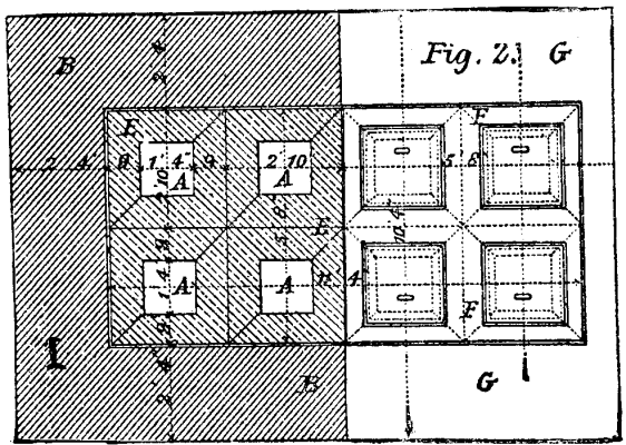
Fig. 2
Every ingot, when cast, contains within itself a considerably
larger store of heat than is necessary for the rolling operation.
Some of this heat is, of course, lost by passing into the mould,
some is lost by radiation before the ingot enters into the soaking
pit, and some is lost after it enters, by being conducted away by
the brickwork; but in the ordinary course of working, when there is
no undue loss of time in transferring the ingots, after allowing
for this loss, there remains a surplus, which goes into the
brickwork of the soaking pits, so that this surplus of heat from
successive ingots tends continually to keep the pits at the intense
heat of the ingot itself. Thus, occasionally it happens that
inadvertently an ingot is delayed so long on its way to the pit as
to arrive there somewhat short of heat, its temperature will be
raised by heat from the walls of the pit itself; the refractory
mass wherein the pit is formed, in fact, acting as an accumulator
of heat, giving and taking heat as required to carry on the
operation in a continuous and practical manner.
GJERS’ SOAKING PITS FOR STEEL INGOTS.
During the soaking operation a quantity of gas exudes from the
ingot and fills the pit, thus entirely excluding atmospheric air
from entering; this is seen escaping round the lid, and when the
lid is removed combustion takes place.
It will be seen by analyses given hereinafter that this gas is
entirely composed of hydrogen, nitrogen, and carbonic oxide, so
that the ingots soak in a perfectly non-oxidizing medium. Hence
loss of steel by oxidation does not take place, and consequently
the great loss of yield which always occurs in the ordinary heating
furnace is entirely obviated.
The author does not think it necessary to dilate upon the
economical advantages of his process, as they are apparent to every
practical man connected with the manufacture of steel.
The operation of steel making on a large scale will by this
process be very much simplified. It will help to dispense with a
large number of men, some of them highly paid, directly and
indirectly connected with the heating department; it will do away
with costly heating furnaces and gas generators, and their costly
maintenance; it will save all the coal used in heating; and what is
perhaps of still more importance, it will save the loss in yield of
steel; and there will be no more steel spoiled by overheating in
the furnaces.
The process has been in operation too short a time to give
precise and reliable figures, but it is hoped that by the next
meeting of the Institute these will be forthcoming from various
quarters.
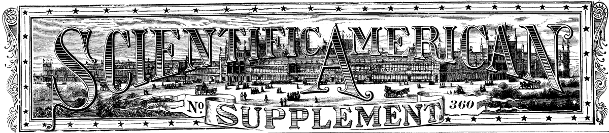
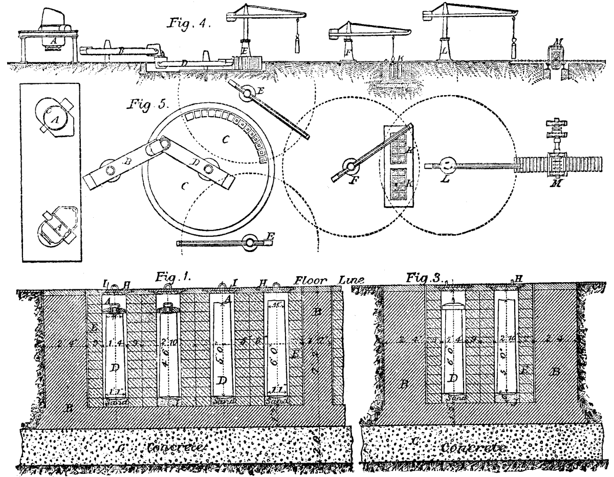
Referring to the illustrations annexed, Fig. 1 shows sectional
elevation, and Fig. 2 plan of a set of eight soaking pits (marked
A). These pits are built in a mass of brickwork, B, on a concrete
foundation, C; the ingots, D, standing upright in the pits. The
pits are lined with firebrick lumps, 6 in. thick, forming an
independent lining, E, which at any time can be readily renewed. F
is a cast iron plate, made to take in four pits, and dropped
loosely within the large plate, G, which surrounds the pits. H is
the cover, with a firebrick lining; and I is a false cover of
firebrick, 1 in. smaller than the cross section of the pit, put in
to rest on the top of the ingot. This false cover need not
necessarily be used, but is useful to keep the extreme top of the
ingot extra hot. J is the bottom of the pit, composed of broken
brick and silver sand, forming a good hard bottom at any desired
level.
Figs. 4 and 5 show outline plan of two sets of soaking pits, K
K, eight each, placed under a 25 ft. sweep crane, L. This crane, if
a good one, could handle any ordinary make–up to 2,000 tons per
week, and ought to have hydraulic racking out and swinging round
gear. This crane places the ingots into the pits, and, when they
are ready, picks them out and swings them round to blooming mill,
M. With such a crane, four men and a boy at the handles are able to
pass the whole of that make through the pits. The author recommends
two sets of pits as shown, although one set of eight pits is quite
able to deal with any ordinary output from one Bessemer pit.
In case of an extraordinarily large output, the author
recommends a second crane, F, for the purpose of placing the ingots
in the pits only, the crane, L, being entirely used for picking the
ingots out and swinging them round to the live rollers of the mill.
The relative position of the cranes, soaking pits, and blooming
mill may of course be variously arranged according to
circumstances, and the soaking pits may be arranged in single or
more rows, or concentrically with the crane at pleasure.
Figs. 4 and 5 also show outline plan and elevation of a Bessemer
plant, conveniently arranged for working on the soaking pit system.
A A are the converters, with a transfer crane, B. C is the casting
pit with its crane, D. E E are the two ingot cranes. F is a leading
crane which transfers the ingots from the ingot cranes to the
soaking pits, K K, commanded by the crane, L, which transfers the
prepared ingots to the mill, M. as before described.
TEMPERING BY COMPRESSION.
L. Clemandot has devised a new method of treating metals,
especially steel, which consists in heating to a cherry red,
compressing strongly and keeping up the pressure until the metal is
completely cooled. The results are so much like those of tempering
that he calls his process tempering by compression. The compressed
metal becomes exceedingly hard, acquiring a molecular contraction
and a fineness of grain such that polishing gives it the appearance
of polished nickel. Compressed steel, like tempered steel, acquires
the coercitive force which enables it to absorb magnetism. This
property should be studied in connection with its durability;
experiments have already shown that there is no loss of magnetism
at the expiration of three months. This compression has no analogue
but tempering. Hammering and hardening modify the molecular state
of metals, especially when they are practiced upon metal that is
nearly cold, but the effect of hydraulic pressure is much greater.
The phenomena which are produced in both methods of tempering may
be interpreted in different ways, but it seems likely that there is
a molecular approximation, an amorphism from which results the
homogeneity that is due to the absence of crystallization. Being an
operation which can be measured, it may be graduated and kept
within limits which are prescribed in advance; directions may be
given to temper at a specified pressure, as readily as to work
under a given pressure of steam.–Chron. Industr.
ECONOMICAL STEAM POWER.
[Footnote: A paper read by title at a recent stated meeting of
the Franklin Institute]
By WILLIAM BARNET LE VAN.
The most economical application of steam power can be realized
only by a judicious arrangement of the plant: namely, the engines,
boilers, and their accessories for transmission.
This may appear a somewhat broad assertion; but it is
nevertheless one which is amply justified by facts open to the
consideration of all those who choose to seek for them.
While it is true that occasionally a factory, mill, or a
water-works may be found in which the whole arrangements have been
planned by a competent engineer, yet such is the exception and not
the rule, and such examples form but a very small percentage of the
whole.
The fact is that but few users of steam power are aware of the
numerous items which compose the cost of economical steam power,
while a yet smaller number give sufficient consideration to the
relations which these items bear to each other, or the manner in
which the economy of any given boiler or engine is affected by the
circumstances under which it is run.
A large number of persons–and they are those who should know
better, too–take for granted that a boiler or engine which is good
for one situation is good for all; a greater error than such an
assumption can scarcely be imagined.
It is true that there are certain classes of engines and boilers
which may be relied upon to give moderately good results in almost
any situation–and the best results should always be desired
in arrangement of a mill–there are a considerable number of
details which must be taken into consideration in making a choice
of boilers and engines.
Take the case of a mill in which it has been supposed that the
motive power could be best exerted by a single engine. The question
now is whether or not it would be best to divide the total power
required among a number of engines.
First.–A division of the motive power presents the
following advantages, namely, a saving of expense on lines of
shafting of large diameter.
Second.–Dispensing with the large driving belt or
gearing, the first named of which, in one instance under the
writer’s observation, absorbed sixty horse-power out of
about 480, or about seven per cent.
Third.–The general convenience of subdividing the work
to be done, so that in case of a stoppage of one portion of the
work by reason of a loose coupling or the changing of a pulley,
etc., that portion only would need to be stopped.
This last is of itself a most important point, and demands
careful consideration.
For example, I was at a mill a short time ago when the governor
belt broke. The result was a stoppage of the whole mill. Had the
motive power of this mill been subdivided into a number of small
engines only one department would have been stopped. During the
stoppage in this case the windows of the mill were a sea of heads
of men and women (the operatives), and considerable excitement was
caused by the violent blowing off of steam from the safety-valves,
due to the stoppage of the steam supply to the engine; and this
excitement continued until the cause of the stoppage was
understood. Had the power in this mill been subdivided the stoppage
of one of a number of engines would scarcely have been noticed, and
the blowing off of surplus steam would not have occurred.
In building a mill the first item to be considered is the
interest on the first cost of the engine, boilers, etc. This item
can be subdivided with advantage into the amounts of interest on
the respective costs of,
First. The engine or engines;
Second The boiler or boilers;
Third. The engine and boiler house.
In the same connection the form of engine to be used must
be considered. In some few cases–as, for instance, where engines
have to be placed in confined situations–the form is practically
fixed by the space available, it being perhaps possible only to
erect a vertical or a horizontal engine, as the case may be. These,
however, are exceptional instances, and in most cases–at all
events where large powers are required–the engineer may have a
free choice in the matter. Under these circumstances the best form,
in the vast majority of cases where machinery must be driven, is
undoubtedly the horizontal engine, and the worst the beam engine.
When properly constructed, the horizontal engine is more durable
than the beam engine, while, its first cost being less, it can be
driven at a higher speed, and it involves a much smaller outlay for
engine house and foundations than the latter. In many respects the
horizontal engine is undoubtedly closely approached in advantages
by the best forms of vertical engines; but on the whole we consider
that where machinery is to be driven the balance of advantages is
decidedly in favor of the former class, and particularly so in the
case of large powers.
The next point to be decided is, whether a condensing or
non-condensing engine should be employed. In settling this question
not only the respective first costs of the two classes of engines
must be taken into consideration, but also the cost of water and
fuel. Excepting, perhaps, in cases of very small powers, and in
those instances where the exhaust steam from a non-condensing
engine can be turned to good account for heating or drying purpose,
it may safely be asserted that in all instances where a sufficient
supply of condensing water is available at a moderate cost, the
extra economy of a well-constructed condensing engine will fully
warrant the additional outlay involved in its purchase. In these
days of high steam pressures, a well constructed non-condensing
engine can, no doubt, be made to approximate closely to the economy
of a condensing engine, but in such a case the extra cost of the
stronger boiler required will go far to balance the additional cost
of the condensing engine.
Having decided on the form, the next question is, what “class”
of engine shall it be; and by the term class I mean the relative
excellence of the engine as a power-producing machine. An automatic
engine costs more than a plain slide-valve engine, but it will
depend upon the cost of fuel at the location where the engine is to
be placed, and the number of hours per day it is kept running, to
decide which class of machine can be adopted with the greatest
economy to the proprietor. The cost of lubricating materials, fuel,
repairs, and percentage of cost to be put aside for depreciation,
will be less in case of the high-class than in the low-class
engine, while the former will also require less boiler power.
Against these advantages are to be set the greater first cost of
the automatic engine, and the consequent annual charge due to
capital sunk. These several items should all be fairly estimated
when an engine is to be bought, and the kind chosen accordingly.
Let us take the item of fuel, for instance, and let us suppose this
fuel to cost four dollars per ton at the place where the engine is
run. Suppose the engine to be capable of developing one hundred
horse-power, and that it consumes five pounds of coal per hour per
horse-power, and runs ten hours per day: this would necessitate the
supply of two and one-half tons per day at a cost of ten dollars
per day. To be really economical, therefore, any improvement which
would effect a saving of one pound of coal per hour per horse-power
must not cost a greater sum per horse-power than that on which the
cost of the difference of the coal saved (one pound of coal per
hour per horse-power, which would be 1,000 pounds per day) for,
say, three hundred days, three hundred thousand (300,000) pounds,
or one hundred and fifty tons (or six hundred dollars), would pay a
fair interest.
Assuming that the mill owner estimates his capital as worth to
him ten per cent, per annum, then the improvement which would
effect the above mentioned saving must not cost more than six
thousand dollars, and so on. If, instead of being run only ten
hours per day, the engine is run night and day, then the outlay
which it would be justifiable to make to effect a certain saving
per hour would be doubled; while, on the other hand, if an engine
is run less than the usual time per day a given saving per hour
would justify a correspondingly less outlay.
It has been found that for grain and other elevators, which are
not run constantly, gas engines, although costing more for the same
power, are cheaper than steam engines for elevating purposes where
only occasionally used.
For this reason it is impossible without considerable
investigation to say what is really the most economical engine to
adopt in any particular case; and as comparatively few users of
steam power care to make this investigation a vast amount of
wasteful expenditure results. Although, however, no absolute rule
can be given, we may state that the number of instances in which an
engine which is wasteful of fuel can be used profitably is
exceedingly small. As a rule, in fact, it may generally be assumed
that an engine employed for driving a manufactory of any kind
cannot be of too high a class, the saving effected by the
economical working of such engines in the vast majority of cases
enormously outweighing the interest on their extra first cost. So
few people appear to have a clear idea of the vast importance of
economy of fuel in mills and factories that I perhaps cannot better
conclude than by giving an example showing the saving to be
effected in a large establishment by an economical engine.
I will take the case of a flouring mill in this city which
employed two engines that required forty pounds of water to be
converted into steam per hour per indicated horse-power. This, at
the time, was considered a moderate amount and the engines were
considered “good.”
These engines indicated seventy horse power each, and ran
twenty-four hours per day on an average of three hundred days each
year, requiring as per indicator diagrams forty million three
hundred and twenty thousand pounds (40 x 70 x 24 x 300 x 2 =
40,320,000) of feed water to be evaporated per annum, which, in
Philadelphia, costs three dollars per horse-power per annum,
amounting to (70 x 2 x 300 = $420.00) four hundred and twenty
dollars.
The coal consumed averaged five and one-half pounds per hour per
horse-power, which, at four dollars per ton, costs
((70 x 2 x 5.5 x 24 x 300) / 2,000) x 4.00= $11,088
Eleven thousand and eighty-eight dollars.
These engines were replaced by one first-class automatic engine,
which developed one hundred and forty-two horse-power per hour with
a consumption of three pounds of coal per hour per
horse-power, and the indicator diagrams showed a consumption of
thirty pounds of water per hour per horse-power. Coal
cost
((142 x 3 x 24 x 300) / 2,000) x 4.00 = $6,134
Six thousand one hundred and thirty-four dollars. Water cost
(142 x 3.00= $426.00) four hundred and twenty-six dollars.
The water evaporated in the latter case to perform the same work
was (142 x 30 x 24 x 300 = 30,672,000) thirty million six hundred
and seventy-two thousand pounds of feed water against (40,320,000)
forty million three hundred and twenty thousand pounds in the
former, a saving of (9,648,000) nine million six hundred and
forty-eight thousand pounds per annum; or,
(40,320,000 – 30,672,000) / 9,648,000 = 31.4 per cent.
—thirty-one and four-tenths per cent.
And a saving in coal consumption of
(11,088 – 6,134) / 4,954 = 87.5 per cent.
—eighty-seven and one-half per cent., or a saving in
dollars and cents of four thousand nine hundred and fifty-four
dollars ($4,954).
In this city, Philadelphia, no allowance for the consumption of
water is made in the case of first class engines, such engines
being charged the same rate per annum per horse-power as an
inferior engine, while, as shown by the above example, a saving in
water of thirty-one and four-tenths per cent. has been
attained by the employment of a first-class engine. The builders of
such engines will always give a guarantee of their consumption of
water, so that the purchaser can be able in advance to estimate
this as accurately as he can the amount of fuel he will use.
RIVER IMPROVEMENTS NEAR ST. LOUIS.
The improvement of the Mississippi River near St. Louis
progresses satisfactorily. The efficacy of the jetty system is
illustrated in the lines of mattresses which showed accumulations
of sand deposits ranging from the surface of the river to nearly
sixteen feet in height. At Twin Hollow, thirteen miles from St.
Louis and six miles from Horse-Tail Bar, there was found a sand bar
extending over the widest portion of the river on which the
engineering forces were engaged. Hurdles are built out from the
shore to concentrate the stream on the obstruction, and then to
protect the river from widening willows are interwoven between the
piles. At Carroll’s Island mattresses 125 feet wide have been
placed, and the banks revetted with stone from ordinary low water
to a 16 foot stage. There is plenty of water over the bar, and at
the most shallow points the lead showed a depth of twelve feet.
Beard’s Island, a short distance further, is also being improved,
the largest force of men at any one place being here engaged. Four
thousand feet of mattresses have been begun, and in placing them
work will be vigorously prosecuted until operations are suspended
by floating ice. The different sections are under the direction of
W. F. Fries, resident engineer, and E. M. Currie, superintending
engineer. There are now employed about 1,200 men, thirty barges and
scows, two steam launches, and the stern-wheel steamer A. A.
Humphreys. The improvements have cost, in actual money expended,
about $200,000, and as the appropriation for the ensuing year
approximates $600,000, the prospect of a clear channel is
gratifying to those interested in the river.
BUNTE’S BURETTE FOR THE ANALYSIS OF FURNACE GASES.
For analyzing the gases of blast-furnaces the various apparatus
of Orsat have long been employed; but, by reason of its simplicity,
the burette devised by Dr. Bünte, and shown in the
accompanying figures, is much easier to use. Besides, it permits of
a much better and more rapid absorption of the oxide of carbon; and
yet, for the lost fractions of the latter, it is necessary to
replace a part of the absorbing liquid three or four times. The
absorbing liquid is prepared by making a saturated solution of
chloride of copper in hydrochloric acid, and adding thereto a small
quantity of dissolved chloride of tin. Afterward, there are added
to the decanted mixture a few spirals of red copper, and the
mixture is then carefully kept from contact with the air.
To fill the burette with gas, the three-way cock, a, is
so placed that the axial aperture shall be in communication with
the graduated part, A, of the burette. After this, water is poured
into the funnel, t, and the burette is put in communication with
the gas reservoir by means of a rubber tube. The lower point of the
burette is put in communication with a rubber pump, V (Fig. 2), on
an aspirator (the cock, b, being left open), and the gas is
sucked in until all the air that was in the apparatus has been
expelled from it. The cocks, a and b, are turned 90
degrees. The water in the funnel prevents the gases communicating
with the top. The point of the three-way cock is afterward closed
with a rubber tube and glass rod.
If the gas happens to be in the reservoir of an aspirator, it is
made to pass into the apparatus in the following manner: The
burette is completely filled with water, and the point of the
three-way cock is put in communication with a reservoir. If the gas
is under pressure, a portion of it is allowed to escape through the
capillary tube into the water in the funnel, by turning the cock,
a, properly, and thus all the water in the conduit is
entirely expelled. Afterward a is turned 180°, and the
lower cock, b, is opened. While the water is flowing through
b, the burette becomes filled with gas.
Mode of Measuring the Gases and Absorption.–The tube
that communicates with the vessel, F, is put in communication,
after the latter has been completely filled with water, with the
point of the cock, b (Fig. 2). Then the latter is opened, as
is also the pinch cock on the rubber tubing, and water is allowed
to enter the burette through the bottom until the level is at the
zero of the graduation. There are then 100 cubic centimeters in the
burette. The superfluous gas has escaped through the cock,
a, and passed through the water in the funnel. The cock,
a, is afterward closed by turning it 90°. To cause the
absorbing liquid to pass into the burette, the water in the
graduated cylinder is made to flow by connecting the rubber tube,
s, of the bottle, S, with the point of the burette. The cock is
opened, and suction is effected with the mouth of the tube, r. When
the water has flowed out to nearly the last drop, b is
closed and the suction bottle is removed. The absorbing liquid
(caustic potassa or pyrogallate of potassa) is poured into a
porcelain capsule, P, and the point of the burette is dipped into
the liquid. If the cock, b, be opened, the absorbing liquid
will be sucked into the burette. In order to hasten the absorption,
the cock, b, is closed, and the burette is shaken
horizontally, the aperture of the funnel being closed by the hand
during the operation.
If not enough absorbing liquid has entered, there may be sucked
into the burette, by the process described above, a new quantity of
liquid. The reaction finished, the graduated cylinder is put in
communication with the funnel by turning the cock, a. The
water is allowed to run from the funnel, and the latter is filled
again with water up to the mark. The gas is then again under the
same pressure as at the beginning.
After the level has become constant, the quantity of gas
remaining is measured. The contraction that has taken place gives,
in hundredths of the total volume, the volume of the gas
absorbed.
When it is desired to make an analysis of smoke due to
combustion, caustic potassa is first sucked into the burette. After
complete absorption, and after putting the gas at the same
pressure, the diminution gives the volume of carbonic acid.
To determine the oxygen in the remaining gas, a portion of the
caustic potash is allowed to flow out, and an aqueous solution of
pyrogallic acid and potash is allowed to enter. The presence of
oxygen is revealed by the color of the liquid, which becomes
darker.
The gas is then agitated with the absorbing liquid until, upon
opening the cock, a, the liquid remains in the capillary
tube, that is to say, until no more water runs from the funnel into
the burette. To make a quantitative analysis of the carbon
contained in gas, the pyrogallate of potash must be entirely
removed from the burette. To do this, the liquid is sucked out by
means of the flask, S, until there remain only a few drops; then
the cock, a, is opened and water is allowed to flow from the
funnel along the sides of the burette. Then a is closed, and
the washing water is sucked in the same manner. By repeating this
manipulation several times, the absorbing liquid is completely
removed. The acid solution of chloride of copper is then allowed to
enter.
As the absorbing liquids adhere to the glass, it is better,
before noting the level, to replace these liquids by water. The
cocks, a and b, are opened, and water is allowed to
enter from the funnel, the absorbing liquid being made to flow at
the same time through the cock, b.
When an acid solution of chloride of copper is employed, dilute
hydrochloric acid is used instead of water.
Fig. 2 shows the arrangement of the apparatus for the
quantitative analysis of oxide of carbon and hydrogen by
combustion. The gas in the burette is first mixed with atmospheric
air, by allowing the liquid to flow through b, and causing
air to enter through the axial aperture of the three way cock,
a, after cutting off communication at v. Then, as shown in
the figure, the burette is connected with the tube, B, which is
filled with water up to the narrow curved part, and the interior of
the burette is made to communicate with the combustion tube, v, by
turning the cock, a. The combustion tube is heated by means of a
Bunsen burner or alcohol lamp, L. It is necessary to proceed, so
that all the water shall be driven from the cock and the capillary
tube, and that it shall be sent into the burette. The combustion is
effected by causing the mixture of gas to pass from the burette
into the tube, B, through the tube, v, heated to redness, into
which there passes a palladium wire. Water is allowed to flow
through the point of the tube, B, while from the flask, F, it
enters through the bottom into the burette, so as to drive out the
gas. The water is allowed to rise into the burette as far as the
cock, and the cocks, b and b¹, are afterward
closed.
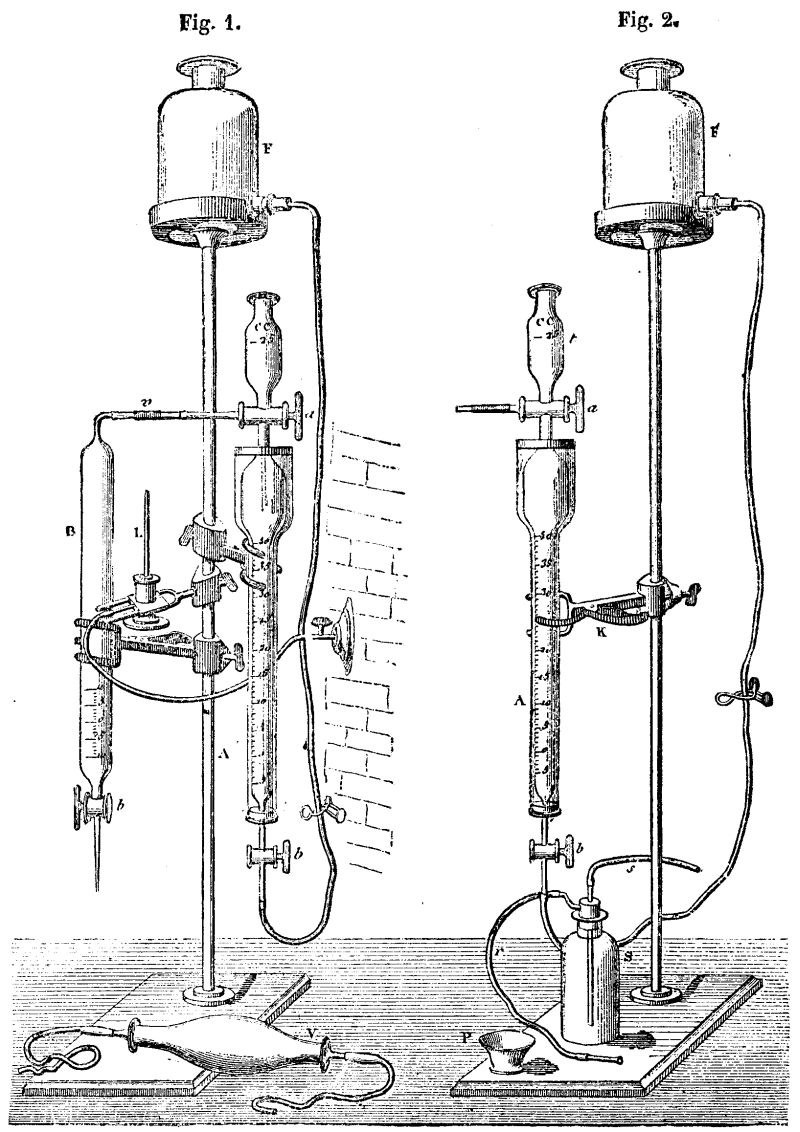
DR. BÜNTE’S GAS BURETTE
By a contrary operation, the gas is made to pass from B into the
burette. It is then allowed to cool, and, after the pressure has
been established again, the contraction is measured. If the gas
burned is hydrogen, the contraction multiplied by two-thirds gives
the original volume of the hydrogen gas burned. If the gas burned
is oxide of carbon, there forms an equal volume of carbonic acid,
and the contraction is the half of CO. Thus, to analyze CO, a
portion of the liquid is removed from the burette, then caustic
potash is allowed to enter, and the process goes on as explained
above.
The total contraction resulting from combustion and absorption,
multiplied by two-thirds, gives the volume of the oxide of
carbon.
The hydrogen and oxide carbon may thus be quantitatively
analyzed together or separately.–Revue Industrielle.
THE “UNIVERSAL” GAS ENGINE.
The accompanying engravings illustrate a new and very simple
form of gas engine, the invention of J. A. Ewins and H. Newman, and
made by Mr. T. B. Barker, of Scholefield-street, Bloomsbury,
Birmingham. It is known as the “Universal” engine, and is at
present constructed in sizes varying from one-eighth
horse-power–one man power–to one horse-power, though larger sizes
are being made. The essentially new feature of the engine is, says
the Engineer, the simple rotary ignition valve consisting of
a ratchet plate or flat disk with a number of small radial slots
which successively pass a small slot in the end of the cylinder,
and through which the flame is drawn to ignite the charge. In our
illustrations Fig. 1 is a side elevation; Fig. 2 an end view of
same; Fig. 3 a plan; Fig. 4 is a sectional view of the chamber in
which the gas and air are mixed, with the valves appertaining
thereto; Fig. 5 is a detail view of the ratchet plate, with pawl
and levers and valve gear shaft; Fig. 6 is a sectional view of a
pump employed in some cases to circulate water through the jacket;
Fig. 7 is a sectional view of arrangement for lighting, and ratchet
plate, j, with central spindle and igniting apertures, and the
spiral spring, k, and fly nut, showing the attachment to the end of
the working cylinder, f1; b5, b5,
bevel wheels driving the valve gear shaft; e, the valve gear
driving shaft; e2, eccentric to drive pump; e³,
eccentric or cam to drive exhaust valve; e4, crank to
drive ratchet plate; e5, connecting rod to ratchet pawl;
f, cylinder jacket; f1, internal or working cylinder;
f2, back cylinder cover; g, igniting chamber; h, mixing
chamber; h1, flap valve; h2, gas inlet valve,
the motion of which is regulated by a governor; h3, gas
inlet valve seat; h4, cover, also forming stop for gas
inlet valve; h5, gas inlet pipe; h6, an inlet
valve; h8, cover, also forming stop for air inlet valve;
h9, inlet pipe for air with grating; i, exhaust chamber;
i2, exhaust valve spindle; i7, exhaust pipe;
j6, lighting aperture through cylinder end; l, igniting
gas jet; m, regulating and stop valve for gas.
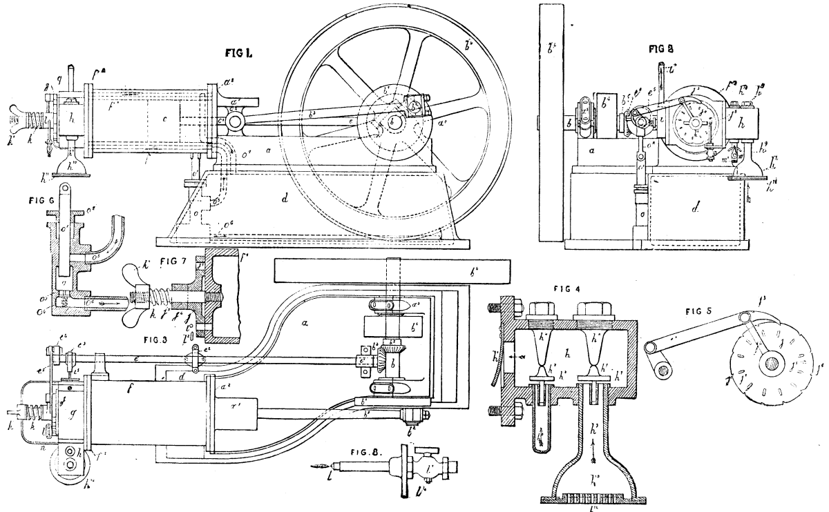
IMPROVED GAS ENGINE
The engine, it will be seen, is single-acting, and no
compression of the explosive charge is employed. An explosive
mixture of combustible gas and air is drawn through the valves,
h2 and h6, and exploded behind the piston
once in a revolution; but by a duplication of the valve and
igniting apparatus, placed also at the front end of the cylinder,
the engine may be constructed double-acting. At the proper time,
when the piston has proceeded far enough to draw in through the
mixing chamber, h, into the igniting chamber, g, the requisite
amount of gas and air, the ratchet plate, j, is pushed into such a
position by the pawl, j3, that the flame from the
igniting jet, l, passes through one of the slots or holes,
j1, and explodes the charge when opposite j6,
which is the only aperture in the end of the working cylinder (see
Fig. 7 and Fig. 2), thus driving the piston on to the end of its
forward stroke. The exhaust valve, Fig. 9, though not exactly of
the form shown, is kept open during the whole of this return stroke
by means of the eccentric, e3, on the shaft working the
ratchet, and thus allowing the products of combustion to escape
through the exhaust pipe, i7, in the direction of the
arrow. Between the ratchet disk and the igniting flame a small
plate not shown is affixed to the pipe, its edge being just above
the burner top. The flame is thus not blown out by the inrushing
air when the slots in ratchet plate and valve face are opposite.
This ratchet plate or ignition valve, the most important in any
engine, has so very small a range of motion per revolution of the
engine that it cannot get out of order, and it appears to require
no lubrication or attention whatever. The engines are working very
successfully, and their simplicity enables them to be made at low
cost. They cost for gas from ½d. to 1½d. per hour for
the sizes mentioned.
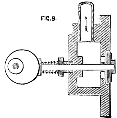
Fig.9.
GAS FURNACE FOR BAKING REFRACTORY PRODUCTS.
In order that small establishments may put to profit the
advantages derived from the use of annular furnaces heated with
gas, smaller dimensions have been given the baking chambers of such
furnaces. The accompanying figure gives a section of a furnace of
this kind, set into the ground, and the height of whose baking
chamber is only one and a half meters. The chamber is not vaulted,
but is covered by slabs of refractory clay, D, that may be
displaced by the aid of a small car running on a movable track.
This car is drawn over the compartment that is to be emptied, and
the slab or cover, D, is taken off and carried over the newly
filled compartment and deposited thereon.
The gas passes from the channel through the pipe, a, into the
vertical conduits, b, and is afterward disengaged through the
tuyeres into the chamber. In order that the gas may be equally
applied for preliminary heating or smoking, a small smoking
furnace, S, has been added to the apparatus. The upper part of this
consists of a wide cylinder of refractory clay, in the center of
whose cover there is placed an internal tube of refractory clay,
which communicates with the channel, G, through a pipe, d. This
latter leads the gas into the tube, t, of the smoking furnace,
which is perforated with a large number of small holes. The air
requisite for combustion enters through the apertures, o, in the
cover of the furnace, and brings about in the latter a high
temperature. The very hot gases descend into the lower iron portion
of this small furnace and pass through a tube, e, into the smoking
chamber by the aid of vertical conduits, b’, which serve at the
same time as gas tuyeres for the extremity of the furnace that is
exposed to the fire.
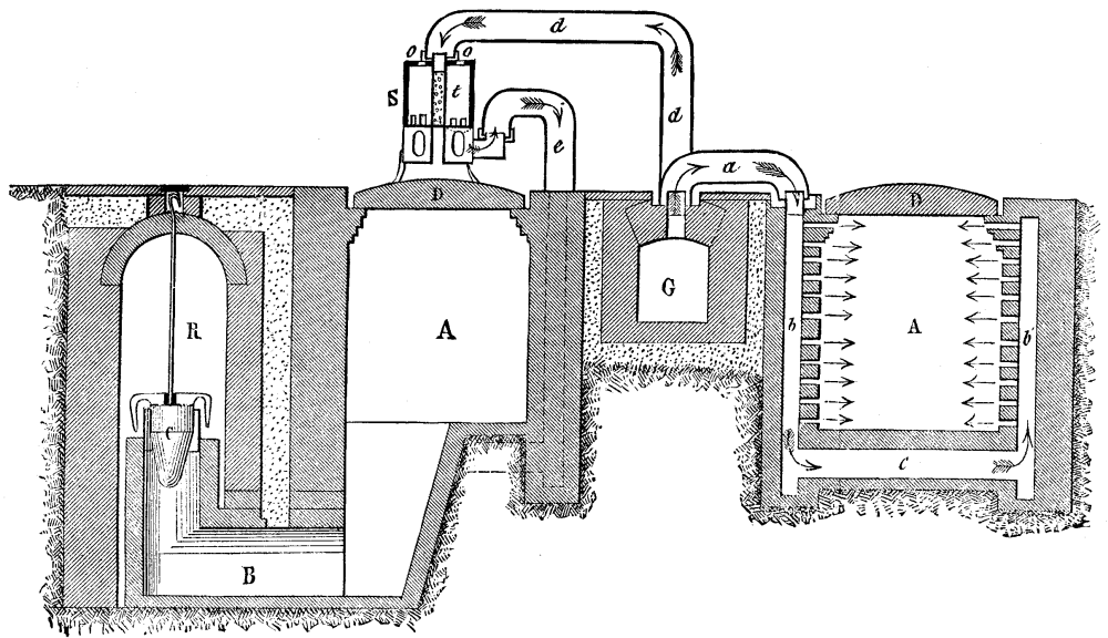
GAS FURNACE FOR BAKING REFRACTORY PRODUCTS.
In the lower part of the smoking furnace, which is made of
boiler plate and can be put in communication with the tube, e,
there are large apertures that may be wholly or partially closed by
means of registers so as to carry to the hot gas derived from
combustion any quantity whatever of cold and dry air, and thus
cause a variation at will of the temperature of the gases which are
disengaged from the tube, e.
The use of these smoking apparatus heated by gas does away also
with the inconveniences of the ordinary system, in which the
products are soiled by cinders or dust, and which render the
gradual heating of objects to be baked difficult. At the beginning,
there is allowed to enter the lower part of the small furnace, S,
through the apertures, a very considerable quantity of cold air, so
as to lower the temperature of the smoke gas that escapes from the
tube, e, to 30 or 50 degrees. Afterward, these secondary air
entrances are gradually closed so as to increase the temperature of
the gases at will.
THE EFFICIENCY OF FANS.
Air, like every other gas or combination of gases, possesses
weight; some persons who have been taught that the air exerts a
pressure of 14.7 lb. per square inch, cannot, however, be got to
realize the fact that a cubit foot of air at the same pressure and
at a temperature of 62 deg. weighs the thirteenth part of a pound,
or over one ounce; 13.141 cubic feet of air weigh one pound. In
round numbers 30,000 cubic feet of air weigh one ton; this is a
useful figure to remember, and it is easily carried in the mind. A
hall 61 feet long, 30 feet wide, and 17 feet high will contain one
ton of air.
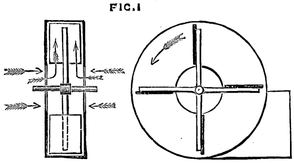
FIG. 1
The work to be done by a fan consists in putting a weight–that
of the air–in motion. The resistances incurred are due to the
inertia of the air and various frictional influences; the nature
and amount of these last vary with the construction of the fan. As
the air enters at the center of the fan and escapes at the
circumference, it will be seen that its motion is changed while in
the fan through a right angle. It may also be taken for granted
that within certain limits the air has no motion in a radial
direction when it first comes in contact with a fan blade. It is
well understood that, unless power is to be wasted, motion should
be gradually imparted to any body to be moved. Consequently, the
shape of the blades ought to be such as will impart motion at first
slowly and afterward in a rapidly increasing ratio to the air. It
is also clear that the change of motion should be effected as
gradually as possible. Fig. 1 shows how a fan should not be
constructed; Fig. 2 will serve to give an idea of how it should be
made.
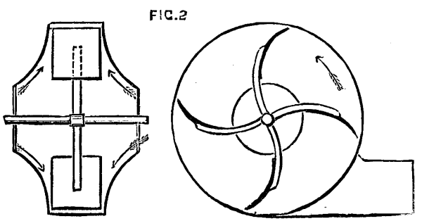
FIG. 2
In Fig. 1 it will be seen that the air, as indicated by the bent
arrows, is violently deflected on entering the fan. In Fig. 2 it
will be seen that it follows gentle curves, and so is put gradually
in motion. The curved form of the blades shown in Fig. 2 does not
appear to add much to the efficiency of a fan; but it adds
something and keeps down noise. The idea is that the fan blades
when of this form push the air radially from the center to the
circumference. The fact is, however, that the air flies outward
under the influence of centrifugal force, and always tends to move
at a tangent to the fan blades, as in Fig. 3, where the circle is
the path of the tips of the fan blades, and the arrow is a tangent
to that path; and to impart this notion a radial blade, as at C, is
perhaps as good as any other, as far as efficiency is concerned.
Concerning the shape to be imparted to the blades, looked at back
or front, opinions widely differ; but it is certain that if a fan
is to be silent the blades must be narrower at the tips than at the
center. Various forms are adopted by different makers, the straight
side and the curved sides, as shown in Fig. 4, being most commonly
used. The proportions as regards length to breadth are also varied
continually. In fact, no two makers of fans use the same
shapes.
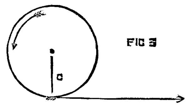
FIG. 3
As the work done by a fan consists in imparting motion at a
stated velocity to a given weight of air, it is very easy to
calculate the power which must be expended to do a certain amount
of work. The velocity at which the air leaves the fan cannot be
greater than that of the fan tips. In a good fan it may be about
two-thirds of that speed. The resistance to be overcome will be
found by multiplying the area of the fan blades by the pressure of
the air and by the velocity of the center of effort, which must be
determined for every fan according to the shape of its blades. The
velocity imparted to the air by the fan will be just the same as
though the air fell in a mass from a given height. This height can
be found by the formula h = v² / 64; that is to say, if the
velocity be multiplied by itself and divided by 64 we have the
height. Thus, let the velocity be 88 per second, then 88 x 88 =
7,744, and 7,744 / 64 = 121. A stone or other body falling from a
height of 121 feet would have a velocity of 88 per second at the
earth. The pressure against the fan blades will be equal to that of
a column of air of the height due to the velocity, or, in this
case, 121 feet. We have seen that in round numbers 13 cubic feet of
air weigh one pound, consequently a column of air one square foot
in section and 121 feet high, will weigh as many pounds as 13 will
go times into 121. Now, 121 / 13 = 9.3, and this will be the
resistance in pounds per square foot overcome by the fan.
Let the aggregate area of all the blades be 2 square feet, and the
velocity of the center of effort 90 feet per second, then the power
expended will bve (90 x 60 x 2 x 9.3) / 33,000 = 3.04 horse power.
The quantity of air delivered ought to be equal in volume to that
of a column with a sectional area equal that of one fan blade
moving at 88 feet per second, or a mile a minute. The blade having
an area of 1 square foot, the delivery ought to be 5,280 feet per
minute, weighing 5,280 / 13 = 406.1 lb. In practice we need hardly
say that such an efficiency is never attained.
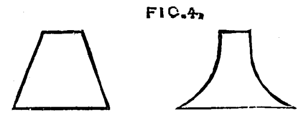
FIG. 4
The number of recorded experiments with fans is very small, and
a great deal of ignorance exists as to their true efficiency. Mr.
Buckle is one of the very few authorities on the subject. He gives
the accompanying table of proportions as the best for pressures of
from 3 to 6 ounces per square inch:
For higher pressures the blades should be longer and narrower,
and the inlet openings smaller. The case is to be made in the form
of an arithmetical spiral widening, the space between the case and
the blades radially from the origin to the opening for discharge,
and the upper edge of the opening should be level with the lower
side of the sweep of the fan blade, somewhat as shown in Fig.
5.
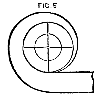
FIG. 5
A considerable number of patents has been taken out for
improvements in the construction of fans, but they all, or nearly
all, relate to modifications in the form of the case and of the
blades. So far, however, as is known, it appears that, while these
things do exert a marked influence on the noise made by a fan, and
modify in some degree the efficiency of the machine, that this last
depends very much more on the proportions adopted than on the
shapes–so long as easy curves are used and sharp angles avoided.
In the case of fans running at low speeds, it matters very little
whether the curves are present or not; but at high speeds the case
is different.–The Engineer.
MACHINE FOR COMPRESSING COAL REFUSE INTO FUEL.
The problem as to how the refuse of coal shall be utilized has
been solved in the manufacture from it of an agglomerated
artificial fuel, which is coming more and more into general use on
railways and steamboats, in the industries, and even in domestic
heating.
The qualities that a good agglomerating machine should present
are as follows:
1. Very great simplicity, inasmuch as it is called upon to
operate in an atmosphere charged with coal dust, pitch, and steam;
and, under such conditions, it is important that it may be easily
got at for cleaning, and that the changing of its parts (which wear
rapidly) may be effected without, so to speak, interrupting its
running.
2. The compression must be powerful, and, that the product may
be homogeneous, must operate progressively and not by shocks. It
must especially act as much as possible upon the entire surface of
the conglomerate, and this is something that most machines fail to
do.
3. The removal from the mould must be effected easily, and not
depend upon a play of pistons or springs, which soon become foul,
and the operation of which is very irregular.
The operations embraced in the manufacture of this kind of fuel
are as follows:
The refuse is sifted in order to separate the dust from the
grains of coal. The dust is not submitted to a washing. The grains
are classed into two sizes, after removing the nut size, which is
sold separately. The grains of each size are washed separately. The
washed grains are either drained or dried by a hydro-extractor in
order to free them from the greater part of the water, the presence
of this being an obstacle to their perfect agglomeration. The
water, however, should not be entirely extracted because the
combustibles being poor conductors of heat, a certain amount of
dampness must be preserved to obtain an equal division of heat in
the paste when the mixture is warmed.
After being dried the grains are mixed with the coal dust, and
broken coal pitch is added in the proportion of eight to ten per
cent. of the coal. The mixture is then thrown into a crushing
machine, where it is reduced to powder and intimately mixed. It
then passes into a pug-mill into which superheated steam is
admitted, and by this means is converted into a plastic paste. This
paste is then led into an agitator for the double purpose of
freeing it from the steam that it contains, and of distributing it
in the moulds of the compressing machine.
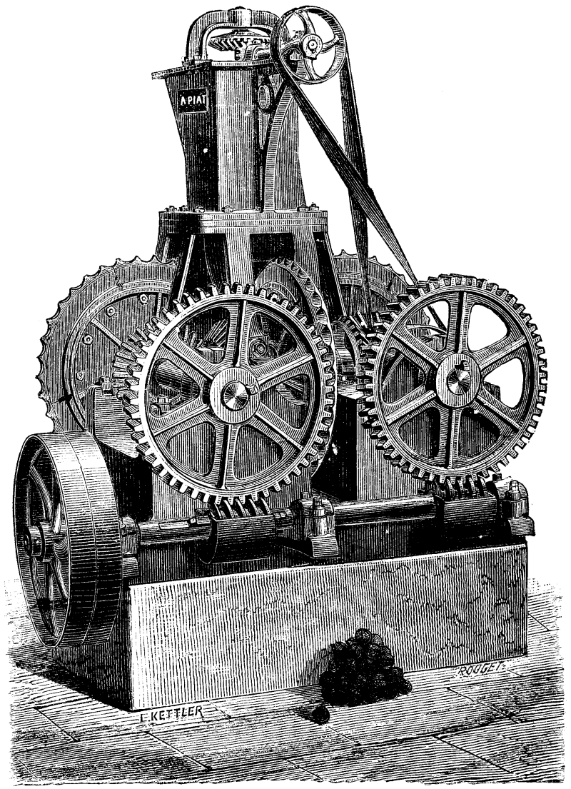
IMPROVED MACHINE FOR COMPRESSING REFUSE COAL INTO
FUEL.
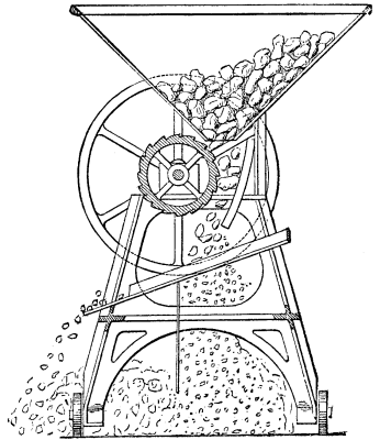
Bilan’s machine, shown in the accompanying cut, is designed for
manufacturing spherical conglomerates for domestic purposes. It
consists of a cast iron frame supporting four vertical moulding
wheels placed at right angles to each other and tangent to the line
of the centers. These wheels carry on their periphery cavities that
have the form of a quarter of a sphere. They thus form at the point
of contact a complete sphere in which the material is inclosed. The
paste is thrown by shovel, or emptied by buckets and chain, into
the hopper fixed at the upper part of the frame. From here it is
taken up by two helices, mounted on a vertical shaft traversing the
hopper, and forced toward the point where the four moulding wheels
meet. The driving pulley of the machine is keyed upon a horizontal
shaft which is provided with two endless screws that actuate two
gear-wheels, and these latter set in motion the four moulding
wheels by means of beveled pinions. The four moulding wheels being
accurately adjusted so that their cavities meet each other at every
revolution, carry along the paste furnished them by the hopper,
compress it powerfully on the four quarters, and, separating by a
further revolution, allow the finished ball to drop out.
The external crown of the wheels carrying the moulds consists of
four segments, which may be taken apart at will to be replaced by
others when worn.
This machine produces about 40 tons per day of this globular
artificial fuel.–Annales Industrielles.
HANK SIZING AND WRINGING MACHINE.
We give a view of a hank sizing machine by Messrs. Heywood &
Spencer, of Radcliffe, near Manchester. The machine is also
suitable for fancy dyeing. It is well known, says the Textile
Manufacturer, that when hanks are wrung by hand, not only is
the labor very severe, but in dyeing it is scarcely possible to
obtain even colors, and, furthermore, the production is limited by
the capabilities of the man. The machine we illustrate is intended
to perform the heavy part of the work with greater expedition and
with more certainty than could be relied upon with hand labor. The
illustration represents the machine that we inspected. Its
construction seems of the simplest character. It consists of two
vats, between which is placed the gearing for driving the hooks.
The large wheel in this gear, although it always runs in one
direction, contains internal segments, which fall into gear
alternately with pinions on the shanks of the hooks. The motion is
a simple one, and it appeared to us to be perfectly reliable, and
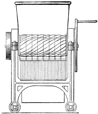
not liable to get out of order. The action is as follows: The
attendant lifts the hank out of the vat and places it on the hooks.
The hook connected to the gearing then commences to turn; it puts
in two, two and a half, three, or more twists into the hank and
remains stationary for a few seconds to allow an interval for the
sizer to “wipe off” the excess of size, that is, to run his hand
along the twisted hank. This done, the hook commences to revolve
the reverse way, until the twists are taken out of the hank. It is
then removed, either by lifting off by hand or by the apparatus
shown, attached to the right hand side. This arrangement consists
of a lattice, carrying two arms that, at the proper moment, lift
the hank off the hooks on to the lattice proper, by which it is
carried away, and dropped upon a barrow to be taken to the drying
stove. In sizing, a double operation is customary; the first is
called running, and the second, finishing. In the machine shown,
running is carried on one side simultaneously with finishing in the
other, or, if required, running may be carried on on both sides. If
desired, the lifting off motion is attached to both running and
finishing sides, and also the roller partly seen on the left hand
for running the hanks through the size. The machine we saw was
doing about 600 bundles per day at running and at finishing, but
the makers claim the production with a double machine to be at the
rate of about 36 10 lb. bundles per hour (at finishing), wrung in
1½ lb. wringers (or I½ lb. of yarn at a time), or at
running at the rate of 45 bundles in 2 lb. wringers. The distance
between the hooks is easily adjusted to the length or size of
hanks, and altogether the machine seems one that is worth the
attention of the trade.
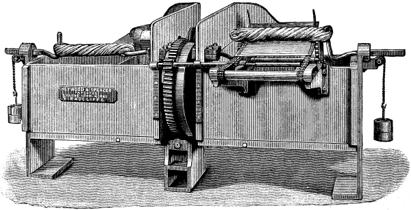
IMPROVED HANK SIZING MACHINE.
IMPROVED COKE BREAKER.
The working parts of the breaker now in use by the South
Metropolitan Gas Company consist essentially of a drum provided
with cutting edges projecting from it, which break up the coke
against a fixed grid. The drum is cast in rings, to facilitate
repairs when necessary, and the capacity of the machine can
therefore be increased or diminished by varying the number of these
rings. The degree of fineness of the coke when broken is determined
by the regulated distance of the grid from the drum. Thus there is
only one revolving member, no toothed gearing being required.
Consequently the machine works with little power; the one at the
Old Kent Road, which is of the full size for large works, being
actually driven by a one horse power “Otto” gas-engine. Under these
conditions, at a recent trial, two tons of coke were broken in half
an hour, and the material delivered screened into the three classes
of coke, clean breeze (worth as much as the larger coke), and dust,
which at these works is used to mix with lime in the purifiers. The
special advantage of the machine, besides the low power required to
drive it and its simple action, lies in the small quantity of
waste. On the occasion of the trial in question, the dust obtained
from two tons of coke measured only 3½ bushels, or just over
a half hundredweight per ton. The following statement, prepared
from the actual working of the first machine constructed, shows the
practical results of its use. It should be premised that the
machine is assumed to be regularly employed and driven by the full
power for which it is designed, when it will easily break 8 tons of
coke per hour, or 80 tons per working day:
As coke, when broken, will usually fetch from 2s. to 2s. 6d. per
ton more than large, the result of using these machines is a net
gain of from 1s. 3d. to 1s. 9d. per ton of coke. It is not so much
the actual gain, however, that operates in favor of providing a
supply of broken coke, as the certainty that by so doing a market
is obtained that would not otherwise be available.
IMPROVED COKE BREAKER.
It will not be overstating the case to say that this coke
breaker is by far the simplest, strongest, and most economical
appliance of its kind now manufactured. That it does its work well
is proved by experience; and the advantages of its construction are
immediately apparent upon comparison of its simple drum and single
spindle with the flying hammers or rocking jaws, or double drums
with toothed gearing which characterize some other patterns of the
same class of plant. It should be remarked, as already indicated,
lest exception should be taken to the size of the machine chosen
here for illustration, that it can be made of any size down to hand
power. On the whole, however, as a few tons of broken coke might be
required at short notice even in a moderate sized works, it would
scarcely be advisable to depend upon too small a machine; since the
regular supply of the fuel thus improved may be trusted in a short
time to increase the demand.
IMPROVED COKE BREAKER.
IMPROVEMENT IN PRINTING MACHINERY.
This is the design of Alfred Godfrey, of Clapton. According to
this improvement, as represented at Figs. 1 and 2, a rack, A, is
employed vibrating on the pivot a, and a pinion, a1, so
arranged that instead of the pinion moving on a universal joint, or
the rack moving in a parallel line from side to side of the pinion
at the time the motion of the table is reversed, there is employed,
for example, the radial arm, a2, mounted on the shaft,
a3, supporting the driving wheel, a4. The
opposite or vibrating end of the radial arm, a2,
supports in suitable bearings the pinion, a1, and wheel,
a5, driving the rack through the medium of the driving
wheel, a4, the effect of which is that through the
mechanical action of the vibrating arm, a2, and pinion,
a1 in conjunction with the vibrating movement of the
rack, A, an easy, uniform, and silent motion is transmitted to the
rack and table.
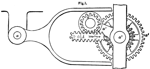
IMPROVEMENTS IN PRINTING MACHINERY. Fig. 1
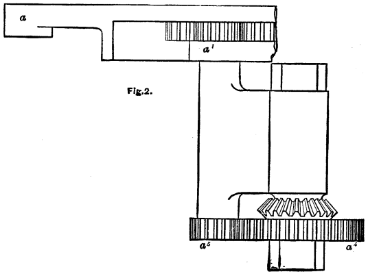
IMPROVEMENTS IN PRINTING MACHINERY. Fig. 2.
A CHARACTERISTIC MINING “RUSH.”–THE PROSPECTIVE MINING CENTER
OF SOUTHERN NEW MEXICO.
A correspondent of the Tribune describes at length the
mining camps about Lake Valley, New Mexico, hitherto thought likely
to be the central camp of that region, and then graphically tells
the story of the recent “rush” to the Perche district. Within a
month of the first strike of silver ore the country was swarming
with prospectors, and a thousand or more prospects had been
located.
The Perche district is on the eastern flanks of the Mimbres
Mountains, a range which is a part of the Rocky Mountain range, and
runs north and south generally parallel with the Rio Grande, from
which it lies about forty miles to the westward. The northern half
of these mountains is known as the Black Range, and was the center
of considerable mining excitement a year and a half ago. It is
there that the Ivanhoe is located, of which Colonel Gillette was
manager, and in which Robert Ingersoll and Senator Plumb, of
Kansas, were interested, much to the disadvantage of the former. A
new company has been organized, however, with Colonel Ingersoll as
president, and the reopening of work on the Ivanhoe will probably
prove a stimulus to the whole Black Range. From this region the
Perche district is from forty to sixty miles south. It is about
twenty-five miles northwest of Lake Valley, and ten miles west of
Hillsboro, a promising little mining town, with some mills and
about 300 people. The Perche River has three forks coming down from
the mountains and uniting at Hillsboro, and it is in the region
between these forks that the recent strikes have been made.
On August 15 “Jack” Shedd, the original discoverer of the
Robinson mine in Colorado, was prospecting on the south branch of
the north fork of the Perche River, when he made the first great
strike in the district. On the summit of a heavily timbered ridge
he found some small pieces of native silver, and then a lump of ore
containing very pure silver in the form of sulphides, weighing 150
pounds, and afterward proved to be worth on the average $11 a
pound. All this was mere float, simply lying on the surface of the
ground. Afterward another block was found, weighing 87 pounds, of
horn silver, with specimens nearly 75 per cent. silver. The strike
was kept a secret for a few days. Said a mining man: “I went up to
help bring the big lump down. We took it by a camp of prospectors
who were lying about entirely ignorant of any find. When they saw
it they instantly saddled their horses, galloped off, and I believe
they prospected all night.” A like excitement was created when the
news of this and one or two similar finds reached Lake Valley. Next
morning every waiter was gone from the little hotel, and a dozen
men had left the Sierra mines, to try their fortunes at
prospecting.
As the news spread men poured into the Perche district from no
one knows where, some armed with only a piece of salt pork, a
little meal, and a prospecting pick; some mounted on mules, others
on foot; old men and men half-crippled were among the number, but
all bitten by the monomania which possesses every prospector. Now
there are probably 2,000 men in the Perche district, and the number
of prospects located must far exceed 1,000. Three miners from there
with whom I was talking recently owned forty-seven mines among
them, and while one acknowledged that hardly one prospect in a
hundred turns out a prize, the other millionaire in embryo remarked
that he wouldn’t take $50,000 for one of his mines. So it goes, and
the victims of the mining fever here seem as deaf to reason as the
buyers of mining stock in New York. Fuel was added to the flame by
the report that Shedd had sold his location, named the Solitaire,
to ex-Governor Tabor and Mr. Wurtzbach on August 25 for $100,000.
This was not true. I met Governor Tabor’s representative, who came
down recently to examine the properties, and learned that the
Governor had not up to that date bought the mine. He undoubtedly
bonded it, however, and his representative’s opinion of the
properties seemed highly favorable. The Solitaire showed what
appeared to be a contact vein, with walls of porphyry and limestone
in a ledge thirty feet wide in places, containing a high assay of
horned silver. The vein was composed of quartz, bearing sulphides,
with horn silver plainly visible, giving an average assay of from
$350 to $500. This was free milling. These were the results shown
simply by surface explorations, which were certainly exceedingly
promising. Recently it has been stated that a little development
shows the vein to be only a blind lead, but the statement lacks
confirmation. In any case the effect of so sensational a discovery
is the same in creating an intense excitement and attracting swarms
of prospectors.
But the Perche district does not rest on the Solitaire, for
there has been abundance of mineral wealth discovered throughout
its extent. Four miles south of this prospect, on the middle fork
of the Perche, is an actual mine–the Bullion–which was purchased
by four or five Western mining men for $10,000, and yielded $11,000
in twenty days. The ore contains horn and native silver. On the
same fork are the Iron King and Andy Johnson, both recently
discovered and promising properties, and there is a valuable mine
now in litigation on the south fork of the Perche, with scores of
prospects over the entire district. Now that one or two sensational
strikes have attracted attention, and capital is developing paying
mines, the future of the Perche District seems assured.
THE SOY BEAN.
The British Medical Journal says that Prof. E. Kinch,
writing in the Agricultural Students’ Gazette, says that the
Soy bean approaches more nearly to animal food than any other known
vegetable production, being singularly rich in fat and in
albuminoids. It is largely used as an article of food in China and
Japan. Efforts have been made to acclimatize it in various parts of
the continent of Europe, and fair success has been achieved in
Italy and France; many foods are made from it and its straw is a
useful fodder.
ON A NEW ARC ELECTRIC LAMP.
[Footnote: Paper read at the British Association, Southampton.
Revised by the Author.–Nature.]
By W.H. PREECE.
Electric lamps on the arc principle are almost as numerous as
the trees in the forest, and it is somewhat fresh to come upon
something that is novel. In these lamps the carbons are consumed as
the current flows, and it is the variation in their consumption
which occasions the flickering and irregularity of the light that
is so irritating to the eyes. Special mechanical contrivances or
regulators have to be used to compensate for this destruction of
the carbons, as in the Siemens and Brush type, or else refractory
materials have to be combined with the carbons, as in the
Jablochkoff candle and in the lamp Soleil. The steadiness of the
light depends upon the regularity with which the carbons are moved
toward each other as they are consumed, so as to maintain the
electric resistance between them a constant quantity. Each lamp
must have a certain elasticity of regulation of its own, to prevent
irregularities from the variable material of carbon used, and from
variations in the current itself and in the machinery.
In all electric lamps, except the Brockie, the regulator is in
the lamp itself. In the Brockie system the regulation is automatic,
and is made at certain rapid intervals by the motor engine. This
causes a periodic blinking that is detrimental to this lamp for
internal illumination.
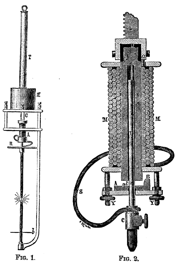
FIG. 1. FIG. 2.
M. Abdank, the inventor of the system which I have the pleasure
of bringing before the Section, separates his regulator from his
lamp. The regulator may be fixed anywhere, within easy inspection
and manipulation, and away from any disturbing influence in the
lamp. The lamp can be fixed in any inaccessible place.
The Lamp (Figs. 1, 2, and 3.)–The bottom or negative
carbon is fixed, but the top or positive carbon is movable, in a
vertical line. It is screwed at the point, C, to a brass rod, T
(Fig. 2), which moves freely inside the tubular iron core of an
electromagnet, K. This rod is clutched and lifted by the soft iron
armature, A B, when a current passes through the coil, M M. The
mass of the iron in the armature is distributed so that the greater
portion is at one end, B, much nearer the pole than the other end.
Hence this portion is attracted first, the armature assumes an
inclined position, maintained by a brass button, t, which prevents
any adhesion between the armature and the core of the
electromagnet. The electric connection between the carbon and the
coil of the electromagnet is maintained by the flexible wire,
S.
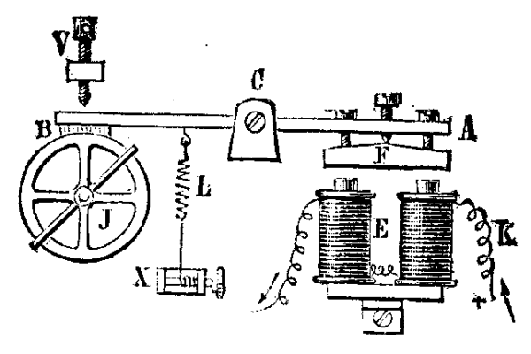
FIG. 3.
The electromagnet, A (Fig. 1), is fixed to a long and heavy
rack, C, which falls by its own weight and by the weight of the
electromagnet and the carbon fixed to it. The length of the rack is
equal to the length of the two carbons. The fall of the rack is
controlled by a friction break, B (Fig. 3), which acts upon the
last of a train of three wheels put in motion by the above weight.
The break, B, is fixed at one end of a lever, B A, the other end
carrying a soft iron armature, F, easily adjusted by three screws.
This armature is attracted by the electromagnet, E E (whose
resistance is 1,200 ohms), whenever a current circulates through
it. The length of the play is regulated by the screw, V. The
spring, L, applies tension to the break.
The Regulator.–This consists of a balance and a
cut-off.
The Balance (Figs. 4 and 5) is made with two solenoids. S
and S’, whose relative resistances is adjustable. S conveys the
main current, and is wound with thick wire having practically no
resistance, and S’ is traversed by a shunt current, and is wound
with fine wire having a resistance of 600 ohms. In the axes of
these two coils a small and light iron tube (2 mm. diameter and 60
mm. length) freely moves in a vertical line between two guides.
When magnetized it has one pole in the middle and the other at each
end. The upward motion is controlled by the spring, N T. The spring
rests upon the screw, H, with which it makes contact by platinum
electrodes. This contact is broken whenever the little iron rod
strikes the spring, N T.
The positive lead from the dynamo is attached to the terminal,
B, then passes through the coil, S, to the terminal, B’, whence it
proceeds to the lamp. The negative lead is attached to terminal, A,
passing directly to the other terminal, A’, and thence to the
lamp.
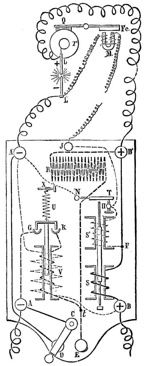
FIG. 4
The shunt which passes through the fine coil, S’, commences at
the point, P. The other end is fixed to the screw, H, whence it has
two paths, the one offering no resistance through the spring, T N,
to the upper negative terminal, A’; the other through the terminal,
J, to the electromagnet of the break, M, and thence to the negative
terminal of the lamp, L’.
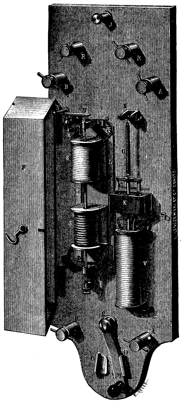
FIG. 5.
The Cut-off.–The last part of the apparatus (Fig. 4) to
be described is the cut-off, which is used when there are several
lamps in series. It is brought into play by the switch, C D, which
can be placed at E or D. When it is at E, the negative terminal, A,
is in communication with the positive terminal, B, through the
resistance, R, which equals the resistance of the lamp, which is,
therefore, out of circuit. When it is at D the cut-off acts
automatically to do the same thing when required. This is done by a
solenoid, V, which has two coils, the one of thick wire offering no
resistance, and the other of 2,000 ohms resistance. The fine wire
connects the terminals, A’ and B. The solenoid has a movable soft
iron core suspended by the spring, U. It has a cross-piece of iron
which can dip into two mercury cups, G and K, when the core is
sucked into the solenoid. When this is the case, which happens when
any accident occurs to the lamp, the terminal, A, is placed in
connection with the terminal, B, through the thick wire of V and
the resistance, R, in the same way as it was done by the switch, C
D.
Electrical Arrangement.–The mode in which several lamps
are connected up in series is shown by Fig. 6. M is the dynamo
machine. The + lead is connected to B1 of the balance it
then passes to the lamp, L, returning to the balance, and then
proceeds to each other lamp, returning finally to the negative pole
of the machine. When the current enters the balance it passes
through the coil, S, magnetizing the iron core and drawing it
downward (Fig. 4). It then passes to the lamp, L L’, through the
carbons, then returns to the balance, and proceeds back to the
negative terminal of the machine. A small portion of the current is
shunted off at the point, P, passing through the coil, S’, through
the contact spring, T N, to the terminal, A’, and drawing the iron
core in opposition to S. The carbons are in contact, but in passing
through the lamp the current magnetizes the electromagnet, M (Fig.
2), which attracts the armature, A B, that bites and lifts up the
rod, T, with the upper carbon, a definite and fixed distance that
is easily regulated by the screws, Y Y. The arc then is formed, and
will continue to burn steadily as long as the current remains
constant. But the moment the current falls, due to the increased
resistance of the arc, a greater proportion passes through the
shunt, S’ (Fig. 4), increasing its magnetic moment on the iron
core, while that of S is diminishing. The result is that a moment
arrives when equilibrium is destroyed, the iron rod strikes smartly
and sharply upon the spring, N T. Contact between T and H is
broken, and the current passes through the electromagnet of the
break in the lamp. The break is released for an instant, the
carbons approach each other. But the same rupture of contact
introduces in the shunt a new resistance of considerable magnitude
(viz., 1,200 ohms), that of the electromagnets of the break. Then
the strength of the shunt current diminishes considerably, and the
solenoid, S, recovers briskly its drawing power upon the rod, and
contact is restored. The carbons approach during these periods only
about 0.01 to 0.02 millimeter. If this is not sufficient to restore
equilibrium it is repeated continually, until equilibrium is
obtained. The result is that the carbon is continually falling by a
motion invisible to the eye, but sufficient to provide for the
consumption of the carbons.
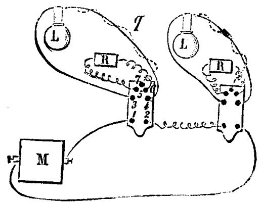
FIG. 6
The contact between N T and H is never completely broken, the
sparks are very feeble, and the contacts do not oxidize. The
resistances inserted are so considerable that heating cannot occur,
while the portion of the current abstracted for the control is so
small that it may be neglected.
The balance acts precisely like the key of a Morse machine, and
the break precisely like the sounder-receiver so well known in
telegraphy. It emits the same kind of sounds, and acts
automatically like a skilled and faithful telegraphist.
This regulation, by very small and short successive steps,
offers several advantages: (1) it is imperceptible to the eye; (2)
it does not affect the main current; (3) any sudden instantaneous
variation of the main current does not allow a too near approach of
the carbon points. Let, now, an accident occur; for instance, a
carbon is broken. At once the automatic cut-off acts, the current
passes through the resistance, R, instead of passing through the
lamp. The current through the fine coil is suddenly increased, the
rod is drawn in, contact is made at G and K, and the current is
sent through the coil, R. As soon as contact is again made by the
carbons, the current in the coil, S, is increased, that of the
thick wire in V diminished, and the antagonistic spring, U, breaks
the contact at G and K. The rupture of the light is almost
invisible, because the relighting is so brisk and sharp.
I have seen this lamp in action, and its constant steadiness
leaves nothing to be desired.
APPARATUS FOR OBTAINING PURE WATER FOR PHOTOGRAPHIC USE.
Our readers are well aware that water as found naturally is
never absolutely free from dissolved impurities; and in ordinary
cases it contains solid impurities derived both from the inorganic
and organic kingdoms, together with gaseous substances; these
latter being generally derived from the atmosphere.
By far the purest water which occurs in nature is rain-water,
and if this be collected in a secluded district, and after the air
has been well washed by previous rain, its purity is remarkable;
the extraneous matter consisting of little else than a trace of
carbonic acid and other gases dissolved from the air. In fact, such
water is far purer than any distilled water to be obtained in
commerce. The case is very different when the rain-water is
collected in a town or densely populated district, more especially
if the water has been allowed to flow over dirty roofs. The black
and foully-smelling liquid popularly known as soft water is so rich
in carbonaceous and organic constituents as to be of very limited
use to the photographer; but by taking the precaution of fitting up
a simple automatic shunt for diverting the stream until the roofs
have been thoroughly washed, it becomes possible to insure a good
supply of clean and serviceable soft water, even in London. Several
forms of shunt have been devised, some of these being so complex as
to offer every prospect of speedy disorganization; but a simple and
efficient apparatus is figured in Engineering by a
correspondent who signs himself “Millwright,” and as we have
thoroughly proved the value of an apparatus which is practically
identical, we reproduce the substance of his communication.
A gentleman of Newcastle, a retired banker, having tried various
filters to purify the rain-water collected on the roof of his
house, at length had the idea to allow no water to run into the
cistern until the roof had been well washed. After first putting up
a hard-worked valve, the arrangement as sketched below has been hit
upon. Now Newcastle is a very smoky place, and yet my friend gets
water as pure as gin, and almost absolutely free from any smack of
soot.
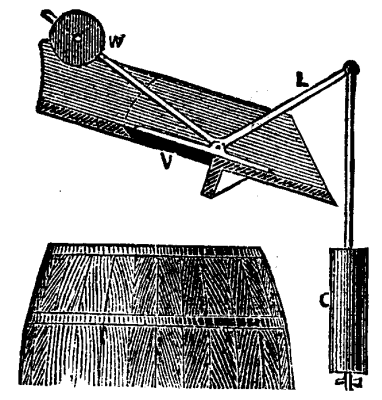
The sketch explains itself. The weight, W, and the angle of the
lever, L, are such, that when the valve, V, is once opened it goes
full open. A small hole in the can C, acts like a cataract, and
brings matters to a normal state very soon after the rain
ceases.
The proper action of the apparatus can only be insured by a
careful adjustment of the weight, W, the angle through which the
valve opens, and the magnitude of the vessel, C. It is an advantage
to make the vessel, C, somewhat broader in proportion to its height
than represented, and to provide it with a movable strainer placed
about half way down. This tends to protect the cataract hole, and
any accumulation of leaves and dirt can be removed once in six
months or so. Clean soft water is valuable to the photographer in
very many cases. Iron developer (wet plate) free from chlorides
will ordinarily remain effective on the plate much longer than when
chlorides are present, and the pyrogallic solution for dry-plate
work will keep good for along time if made with soft water, while
the lime which is present in hard water causes the pyrogallic acid
to oxidize with considerable rapidity. Negatives that have been
developed with oxalate developer often become covered with a very
unsightly veil of calcium oxalate when rinsed with hard water, and
something of a similar character occasionally occurs in the case of
silver prints which are transferred directly from the exposure
frame to impure water.
To the carbon printer clean rain-water is of considerable value,
as he can develop much more rapidly with soft water than with hard
water; or, what comes to the same thing, he can dissolve away his
superfluous gelatine at a lower temperature than would otherwise be
necessary.
The cleanest rain-water which can ordinarily be collected in a
town is not sufficiently pure to be used with advantage in the
preparation of the nitrate bath, it being advisable to use the
purest distilled water for this purpose; and in many cases it is
well to carefully distill water for the bath in a glass apparatus
of the kind figured below.
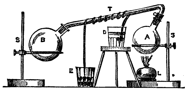
A, thin glass flask serving as a retort. The tube, T, is fitted
air-tight to the flask by a cork, C.
B, receiver into which the tube, T, fits quite loosely.
D, water vessel intended to keep the spiral of lamp wick, which
is shown as surrounding T, in a moist condition. This wick acts as
a siphon, and water is gradually drawn over into the lower
receptacle, E.
L, spirit lamp, which may, in many cases, be advantageously
replaced by a Bunsen burner.
A small metal still, provided with a tin condensing worm, is,
however, a more generally serviceable arrangement, and if ordinary
precautions are taken to make sure that the worm tube is clean, the
resulting distilled water will be nearly as pure as that distilled
in glass vessels.
Such a still as that figured below can be heated conveniently
over an ordinary kitchen fire, and should find a place among the
appliances of every photographer. Distilled water should always be
used in the preparation of emulsion, as the impurities of ordinary
water may often introduce disturbing conditions.–Photographic
News.
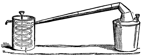
BLACK PHOSPHORUS.
By P. THENARD.
The author refers to the customary view that black phosphorus is
merely a mixture of the ordinary phosphorus with traces of a
metallic phosphide, and contends that this explanation is not in
all cases admissible. A specimen of black or rather dark gray
phosphorus, which the author submitted to the Academy, became white
if melted and remained white if suddenly cooled, but if allowed to
enter into a state of superfusion it became again black on contact
with either white or black phosphorus. A portion of the black
specimen being dissolved in carbon disulphide there remained
undissolved merely a trace of a very pale yellow matter which
seemed to be amorphous phosphorus.–Comptes Rendus.
COMPOSITION OF STEEP WATER.
According to M. C. Leeuw, water in which malt has been steeped
has the following composition:
The mineral matter consists of–
SCHREIBER’S APPARATUS FOR REVIVIFYING BONE-BLACK.
We give opposite illustrations of Schreiber’s apparatus for
revivifying bone-black or animal charcoal. The object of
revivification is to render the black fit to be used again after it
has lost its decolorizing properties through service–that is to
say, to free its pores from the absorbed salts and insoluble
compounds that have formed therein during the operation of sugar
refining. There are two methods employed–fermentation and washing.
At present the tendency is to abandon the former in order to
proceed with as small a stock of black as possible, and to adopt
the method of washing with water and acid in a rotary washer.
Figs. 1 and 2 represent a plan and elevation of a bone-black
room, containing light filters, A, arranged in a circle around
wells, B. These latter have the form of a prism with trapezoidal
base, whose small sides end at the same point, d, and the large
ones at the filter. The funnel, E, of the washer, F, is placed in
the space left by the small ends of the wells, so that the black
may be taken from these latter and thrown directly into the washer.
The washer is arranged so that the black may flow out near the
steam fitter, G, beneath the floor. The discharge of this filter is
toward the side of the elevator, H, which takes in the wet black
below, and carries it up and pours it into the drier situated at
the upper part of the furnace. This elevator, Figs. 3 and 4, is
formed of two vertical wooden uprights, A, ten centimeters in
thickness, to which are fixed two round-iron bars the same as
guides. The lift, properly so-called, consists of an iron frame, C,
provided at the four angles with rollers, D, and supporting a
swinging bucket, E, which, on its arrival at the upper part of the
furnace, allows the black to fall to an inclined plane that leads
it to the upper part of the drier. The left is raised and lowered
by means of a pitch-chain, F, fixed to the middle of the frame, C,
and passing over two pulleys, G, at the upper part of the frame and
descending to the mechanism that actuates it. This latter comprises
a nut, I, acting directly on the chain; a toothed wheel, K, and a
pinion, J, gearing with the latter and keyed upon the shaft of the
pulleys, L and M. The diameter of the toothed wheel, K, is 0.295 of
a meter, and it makes 53.4 revolutions per minute. The diameter of
the pinion is 0.197 of a meter, and it makes 80 revolutions per
minute. The pulleys, M and L, are 0.31 of a meter in diameter, and
make 80 revolutions per minute. Motion is transmitted to them by
other pulleys, N, keyed upon a shaft placed at the lower part,
which receives its motion from the engine of the establishment
through the intermedium of the pulley, O. The diameter of the
latter is 0.385 of a meter, and that of N is 0.58. They each make
43 revolutions per minute.
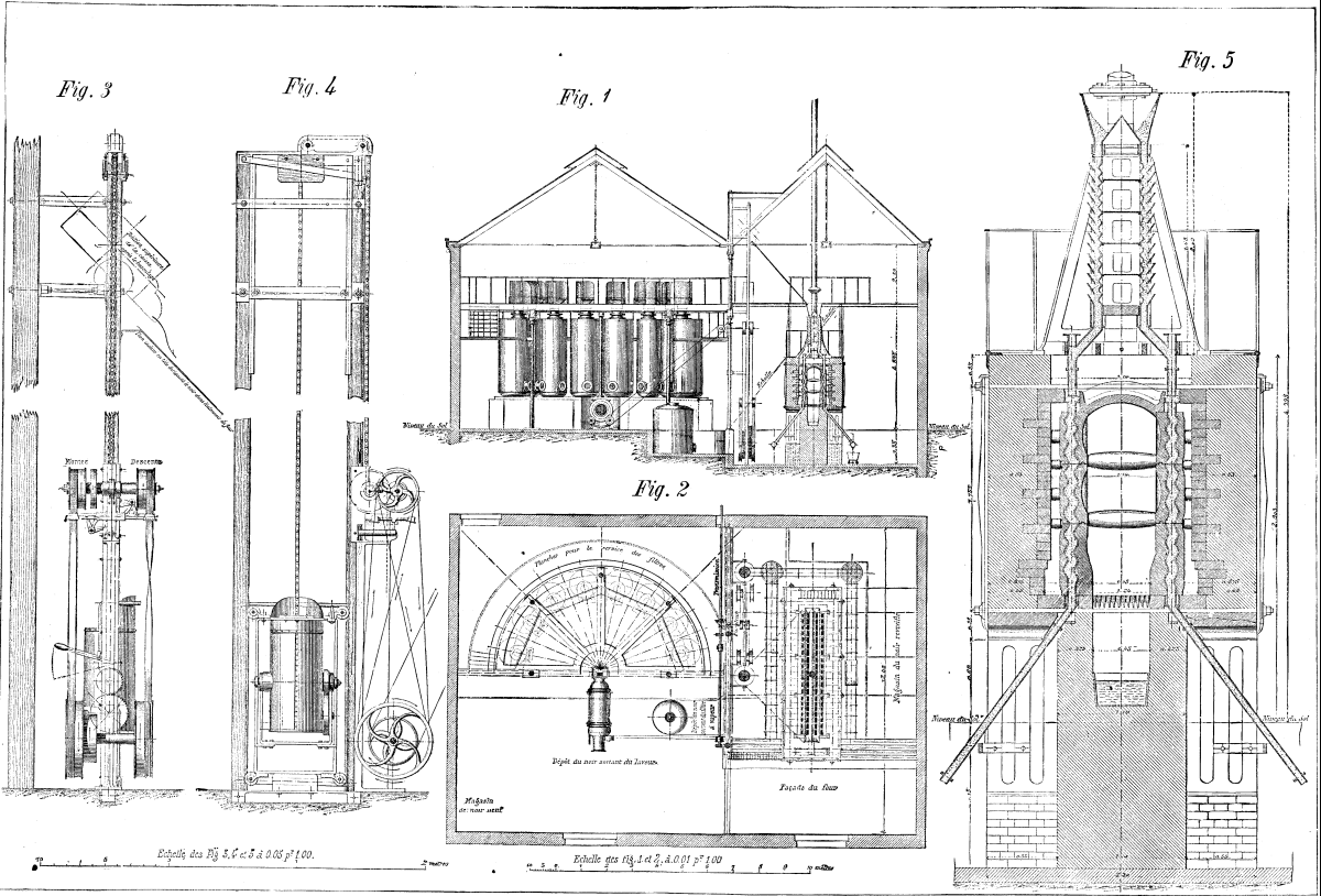
FIG. 1.–ELEVATION OF BONE-BLACK REVIVIFYING PLANT
(SCHREIBER’S SYSTEM.)
FIG. 2.–PLAN VIEW.
FIG. 3.–LATERAL VIEW OF ELEVATOR.
FIG. 4.–FRONT VIEW OF ELEVATOR.
FIG. 5.–CONTINUOUS FURNACE FOR REVIVIFYING BONE-BLACK.
The elevator is set in motion by the simple maneuver of the
gearing lever, P, and when this has been done all the other motions
are effected automatically.
The Animal Black Furnace.–This consists of a masonry
casing of rectangular form, in which are arranged on each side of
the same fire-place two rows of cast-iron retorts, D, of undulating
form, each composed of three parts, set one within the other. These
retorts, which serve for the revivification of the black, are
incased in superposed blocks of refractory clay, P, Q, S, designed
to regularize the transmission of heat and to prevent burning.
These pieces are kept in their respective places by crosspieces, R.
The space between the retorts occupied by the fire-place, Y, is
covered with a cylindrical dome, O, of refractory tiles, forming a
fire-chamber with the inner surface of the blocks, P, Q, and S. The
front of the surface consists of a cast-iron plate, containing the
doors to the fire-place and ash pan, and a larger one to allow of
entrance to the interior to make repairs.
One of the principal disadvantages of furnaces for revivifying
animal charcoal has been that they possessed no automatic drier for
drying the black on its exit from the washer. It was for the
purpose of remedying this that Mr. Schreiber was led to invent the
automatic system of drying shown at the upper part of the furnace,
and which is formed of two pipes, B, of undulating form, like the
retorts, with openings throughout their length for the escape of
steam. Between these pipes there is a closed space into which
enters the waste heat and products of combustion from the furnace.
These latter afterward escape through the chimney at the upper
part.
In order that the black may be put in bags on issuing from the
furnace, it must be cooled as much as possible. For this purpose
there are arranged on each side of the furnace two pieces of cast
iron tubes, F, of rectangular section, forming a prolongation of
the retorts and making with them an angle of about 45 degrees. The
extremities of these tubes terminate in hollow rotary cylinders, G,
which permit of regulating the flow of the black into a car, J
(Fig. 1), running on rails.
From what precedes, it will be readily understood how a furnace
is run on this plan.
The bone-black in the hopper, A, descends into the drier, B,
enters the retorts, D, and, after revivification, passes into the
cooling pipes, F, from whence it issues cold and ready to be
bagged. A coke fire having been built in the fire-place, Y, the
flames spread throughout the fire chamber, direct themselves toward
the bottom, divide into two parts to the right and left, and heat
the back of the retorts in passing. Then the two currents mount
through the lateral flues, V, and unite so as to form but one in
the drier. Within the latter there are arranged plates designed to
break the current from the flames, and allow it to heat all the
inner parts of the pipes, while the apertures in the drier allow of
the escape of the steam.
By turning one of the cylinders, G, so as to present its
aperture opposite that of the cooler, it instantly fills up with
black. At this moment the whole column, from top to bottom, is set
in motion. The bone-black, in passing through the undulations, is
thrown alternately to the right and left until it finally reaches
the coolers. This operation is repeated as many times as the
cylinder is filled during the descent of one whole column, that is
to say, about forty times.
With an apparatus of the dimensions here described, 120
hectoliters of bone-black may be revivified in twenty four hours,
with 360 to 400 kilogrammes of coke.–Annales
Industrielles.
[Continued from SUPPLEMENT, No. 330, page 5264.]
SOAP AND ITS MANUFACTURE, FROM A CONSUMER’S POINT OF VIEW.
In our last article, under the above heading, the advantages to
be gained by the use of potash soap as compared with soda soap were
pointed out, and the reasons of this superiority, especially in the
case of washing wool or woolen fabrics, were pretty fully gone
into. It was also further explained why the potash soaps generally
sold to the public were unfit for general use, owing to their not
being neutral–that is to say, containing a considerable excess of
free or unsaponified alkali, which acts injuriously on the fiber of
any textile material, and causes sore hands if used for household
or laundry purposes. It was shown that the cause of this defect was
owing to the old-fashioned method of making potash or soft soap, by
boiling with wood ashes or other impure form of potash; but that a
perfectly pure and neutral potash soap could readily be made with
pure caustic potash, which within the last few years has become a
commercial article, manufactured on a large scale; just in the same
manner as the powdered 98 per cent. caustic soda, which was
recommended in our previous articles on making hard soap without
boiling.
The process of making pure neutral potash soap is very simple,
and almost identical with that for making hard soap with pure
powdered caustic soda. The following directions, if carefully and
exactly followed, will produce a first-class potash soap, suitable
either for the woolen manufacturer for washing his wool, and the
cloth afterward made from it, or for household and laundry
purposes, for which uses it will be found far superior to any soda
soap, no matter how pure or well made it may be.
Dissolve twenty pounds of pure caustic potash in two gallons of
water. Pure caustic potash is very soluble, and dissolves almost
immediately, heating the water. Let the lye thus made cool until
warm to the hand–say about 90 F. Melt eighty pounds of tallow or
grease, which must be free from salt, and let it cool until fairly
hot to the hand–say 130 F.; or eighty pounds of any vegetable or
animal oil may be taken instead. Now pour the caustic potash lye
into the melted tallow or oil, stirring with a flat wooden stirrer
about three inches broad, until both are thoroughly mixed and
smooth in appearance. This mixing may be done in the boiler used to
melt the tallow, or in a tub, or half an oil barrel makes a good
mixing vessel. Wrap the tub or barrel well up in blankets or
sheepskins, and put away for a week in some warm dry place, during
which the mixture slowly turns into soap, giving a produce of about
120 pounds of excellent potash soap. If this soap is made with
tallow or grease it will be nearly as hard as soda soap. When made
by farmers or householders tallow or grease will generally be
taken, as it is the cheapest, and ready to hand on the spot. For
manufacturers, or for making laundry soap, nothing could be better
than cotton seed oil. A magnificent soap can be made with this
article, lathering very freely. When made with oil it is better to
remelt in a kettle the potash soap, made according to the above
directions, with half its weight of water, using very little heat,
stirring constantly, and removing the fire as soon as the water is
mixed with and taken up by the soap. A beautifully bright soap is
obtained in this way, and curiously the soap is actually made much
harder and stiffer by this addition of water than when it is in a
more concentrated state previously to the water being added.
With reference to the caustic potash for making the soap, it can
be obtained in all sizes of drums, but small packages just
sufficient for a batch of soap are generally more economical than
larger packages, as pure caustic potash melts and deteriorates very
quickly when exposed to the air. The Greenbank Alkali Co., of St.
Helens, seems to have appreciated this, and put upon the market
pure caustic potash in twenty pound canisters, which are very
convenient for potash soft soap making by consumers for their own
use.
While on this subject of caustic potash, it cannot be too often
repeated that caustic potash is a totally different article
to caustic soda, though just like it in appearance, and
therefore often sold as such. One of the most barefaced instances
of this is the so-called “crystal potash,” “ball potash,” or “rock
potash,” of the lye packers, sold in one pound packages, which
absolutely, without exception, do not contain a single grain of
potash, but simply consist of caustic soda more or less
adulterated–as a rule very much “more” than “less!” It is much to
be regretted that this fraud on the public has been so extensively
practiced, as potash has been greatly discredited by this
procedure.
The subject of fleece scouring or washing the wool while growing
on the sheep, with a potash soap made on the spot with the waste
tallow generally to be had on every sheep farm, seems recently to
have been attracting attention in some quarters, and certainly
would be a source of profit to sheep owners by putting their wool
on the market in the best condition, and at the same time cleaning
the skin of the sheep. It therefore appears to be a move in the
right direction.
In concluding this series of articles on practical soap making
from a consumer’s point of view, the writer hopes that, although
the subject has been somewhat imperfectly handled, owing to
necessarily limited space and with many unavoidable interruptions,
yet that they may have been found of some interest and assistance
to consumers of soap who desire easily and readily to make a pure
and unadulterated article for their own use.
COTTON SEED OIL.
By S.S. BRADFORD, Ph.G.
Having had occasion during the last six years to manufacture
lead plaster in considerable quantities, it occurred to me that
cotton seed oil might be used instead of olive oil, at less
expense, and with as good results. The making of this plaster with
cotton seed oil has been questioned, as, according to some
authorities, the product is not of good consistence, and is apt to
be soft, sticky, and dark colored; but in my experience such is not
the case. If the U. S. P. process is followed in making this
plaster, substituting for the olive oil cotton seed oil, and
instead of one half-pint of boiling water one and one-half pint are
added, the product obtained will be equally as good as that from
olive oil. My results with this oil in making lead plaster led me
to try it in making the different liniments of the Pharmacopoeia,
with the following results:
Linimentum Ammoniæ.–This liniment, made with
cotton seed oil, is of much better consistency than when made with
olive oil. It is not so thick, will pour easily out of the bottle,
and if the ammonia used is of proper strength, will make a perfect
liniment.
Linimentum Calcis.–Cotton seed oil is not at all adapted
to making this liniment. It does not readily saponify, separates
quickly, and it is almost impossible to unite when separated.
Linimentum Camphoræ.–Cotton seed oil is far
superior to olive oil in making this liniment, it being a much
better solvent of camphor. It has not that disagreeable odor so
commonly found in the liniment.
Linimentum Chloroformi.–Cotton seed oil being very
soluble in chloroform, the liniment made with it leaves nothing to
be desired.
Linimentum Plumbi Subacetatis.–When liq. plumbi subacet.
is mixed with cotton seed oil and allowed to stand for some time
the oil assumes a reddish color similar to that of freshly made
tincture of myrrh. When the liquor is mixed with olive oil, if the
oil be pure, no such change takes place. Noticing this change, it
occurred to me that this would be a simple and easy way to detect
cotton seed oil when mixed with olive oil. This change usually
takes place after standing from twelve to twenty-four hours. It is
easily detected in mixtures containing five per cent., or even
less, of the oils, and I am convinced, after making numerous
experiments with different oils, that it is peculiar to cotton seed
oil.–American Journal of Pharmacy.
THE FOOD AND ENERGY OF MAN.
[Footnote: From a lecture delivered at the Sanitary Congress, at
Newcastle-on-Tyne, September 28, 1882.]
By PROF. DE CHAUMONT, F.R.S.
Although eating cannot be said to be in any way a new fashion,
it has nevertheless been reserved for modern times, and indeed we
may say the present generation, to get a fairly clear idea of the
way in which food is really utilized for the work of our bodily
frame. We must not, however, plume ourselves too much upon our
superior knowledge, for inklings of the truth, more or less dim,
have been had through all ages, and we are now stepping into the
inheritance of times gone by, using the long and painful experience
of our predecessors as the stepping-stone to our more accurate
knowledge of the present time. In this, as in many other things, we
are to some extent in the position of a dwarf on the shoulders of a
giant; the dwarf may, indeed, see further than the giant; but he
remains a dwarf, and the giant a giant.
The question has been much discussed as to what the original
food of man was, and some people have made it a subject of excited
contention. The most reasonable conclusion is that man is naturally
a frugivorous or fruit-eating animal, like his cousins the monkeys,
whom he still so much resembles. This forms a further argument in
favor of his being originated in warm regions, where fruits of all
kinds were plentiful. It is pretty clear that the resort to animal
food, whether the result of the pressure of want from failure of
vegetable products, or a mere taste and a desire for change and
more appetizing food, is one that took place many ages ago,
probably in the earliest anthropoid, if not in the latest pithecoid
stage. No doubt some advantage was recognized in the more rapid
digestion and the comparative ease with which the hunter or fisher
could obtain food, instead of waiting for the ripening of fruits in
countries which had more or less prolonged periods of cold and
inclement weather. Some anatomical changes have doubtless resulted
from the practice, but they are not of sufficiently marked
character to found much argument upon; all that we can say being
that the digestive apparatus in man seems well adapted for
digesting any food that is capable of yielding nutriment, and that
even when an entire change is made in the mode of feeding, the
adaptability of the human system shows itself in a more or less
rapid accommodation to the altered circumstances.
Food, then, is any substance which can be taken into the body
and applied to use, either in building up or repairing the tissues
and framework of the body itself, or in providing energy and
producing animal heat, or any substance which, without performing
those functions directly, controls, directs, or assists their
performance. With this wide definition it is evident that we
include all the ordinary articles recognized commonly as food, and
that we reject all substances recognized commonly as poisons. But
it will also include such substances as water and air, both of
which are essential for nutrition, but are not usually recognized
as belonging to the list of food substances in the ordinary sense.
When we carry our investigation further, we find that the organic
substances may be again divided into two distinct classes, namely,
that which contains nitrogen (the casein), and those that do not
(the butter and sugar).
On ascertaining this, we are immediately struck with the
remarkable fact that all the tissues and fluids of the body,
muscles (or flesh), bone, blood–all, in short, except the
fat–contain nitrogen, and, consequently, for their building up in
the young, and for their repair and renewal in the adult, nitrogen
is absolutely required. We therefore reasonably infer that the
nitrogenous substance is necessary for this purpose. Experiment has
borne this out, for men who have been compelled to live without
nitrogenous food by dire necessity, and criminals on whom the
experiment has been tried, have all perished sooner or later in
consequence. When nitrogenous substances are used in the body, they
are, of course, broken up and oxidized, or perhaps we ought to say
more accurately, they take the place of the tissues of the body
which wear away and are carried off by oxidation and other chemical
changes.
Now, modern science tell us that such changes are accompanied
with manifestations of energy in some form or other, most
frequently in that of heat, and we must look, therefore, upon
nitrogenous food as contributing to the energy of the body in
addition to its other functions.
What are the substances which we may class as nitrogenous. In
the first place, we have the typical example of the purest form in
albumin, or white of egg; and from this the name is now
given to the class of albuminates. The animal albuminates
are: Albumin from eggs, fibrin from muscles, or flesh, myosin, or
synronin, also from animals, casein (or cheesy matter) from milk,
and the nitrogenous substances from blood. In the vegetable
kingdom, we have glutin, or vegetable fibrin, which is the
nourishing constituent of wheat, barley, oats, etc.; and legumin,
or vegetable casein, which is the peculiar substance found in peas
and beans. The other organic constituents–viz., the fats and the
starches and sugars–contain no nitrogen, and were at one time
thought to be concerned in producing animal heat.
We now know–thanks to the labors of Joule, Lyon Playfair,
Clausius, Tyndall, Helmholtz, etc.–that heat itself is a mode of
motion, a form of convertible energy, which can be made to do
useful or productive work, and be expressed in terms of actual work
done. Modern experiment shows that all our energy is derived from
that of food, and, in particular from the non-nitrogenous part of
it, that is, the fat, starch, and sugar. The nutrition of man is
best maintained when he is provided with a due admixture of all the
four classes of aliment which we have mentioned, and not only that,
but he is also better off if he has a variety of each class. Thus
he may and ought to have albumen, fibrine, gluten, and casein among
the albuminates, or at least two of them; butter and lard, or suet,
or oil among the fats; starch of wheat, potato, rice, peas, etc.,
and cane-sugar, and milk-sugar among the carbo-hydrates. The salts
cannot be replaced, so far as we know. Life may be maintained in
fair vigor for some time on albuminates only, but this is done at
the expense of the tissues, especially the fat of the body, and the
end must soon come; with fat and carbo hydrates alone vigor may
also be maintained for some time, at the expense of the tissues
also, but the limit is a near one, In either of these cases we
suppose sufficient water and salts to be provided.
We must now inquire into the quantities of food necessary; and
this necessitates a little consideration of the way in which the
work of the body is carried on. We must look upon the human body
exactly as a machine; like an engine with which we are all so
familiar. A certain amount of work requires to be done, say, a
certain number of miles of distance to be traversed; we know that
to do this a certain number of pounds, or hundredweights, or tons
of coal must be put into the fire of the boiler in order to furnish
the requisite amount of energy through the medium of steam. This
amount of fuel must bear a certain proportion to the work, and also
to the velocity with which it is done, so both quantity and time
have to be accounted for.
No lecture on diet would be complete without a reference to the
vexed question of alcohol. I am no teetotal advocate, and I
repudiate the rubbish too often spouted from teetotal platforms,
talk that is, perhaps, inseparable from the advocacy of a cause
that imports a good deal of enthusiasm. I am at one, however, in
recognizing the evils of excess, and would gladly hail their
diminution. But I believe that alcohol properly used may be a
comfort and a blessing, just as I know that improperly used it
becomes a bane and a curse. But we are now concerned with it as an
article of diet in relation to useful work, and it may be well to
call attention markedly to the fact that its use in this way is
very limited. The experiments of the late Dr. Parkes, made in our
laboratory, at Netley, were conclusive on the point, that beyond an
amount that would be represented by about one and a half to two
pints of beer, alcohol no longer provided any convertible energy,
and that, therefore, to take it in the belief that it did do so is
an error. It may give a momentary stimulus in considerable doses,
but this is invariably followed by a corresponding depression, and
it is a maxim now generally followed, especially on service, never
to give it before or during work. There are, of course, some
persons who are better without it altogether, and so all moderation
ought to be commended, if not enjoyed.
There are other beverages which are more useful than the
alcoholic, as restoratives, and for support in fatigue. Tea and
coffee are particularly good. Another excellent restorative is a
weak solution of Liebig’s extract of meat, which has a remarkable
power of removing fatigue. Perhaps one of the most useful and most
easily obtainable is weak oatmeal gruel, either hot or cold. With
regard to tobacco, it also has some value in lessening fatigue in
those who are able to take it, but it may easily be carried to
excess. Of it we may say, as of alcohol, that in moderation it
seems harmless, and even useful to some extent, but, in excess, it
is rank poison.
There is one other point which I must refer to, and which is
especially interesting to a great seaport like this. This is the
question of scurvy–a question of vital importance to a maritime
nation. A paper lately issued by Mr. Thomas Gray, of the Board of
Trade, discloses the regrettable fact that since 1873 there has
been a serious falling off, the outbreaks of scurvy having again
increased until they reached ninety-nine in 1881. This, Mr. Gray
seems to think, is due to a neglect of varied food scales; but it
may also very probably have arisen from the neglect of the
regulation about lime-juice, either as to issue or quality, or
both. But it is also a fact of very great importance that mere
monotony of diet has a most serious effect upon health; variety of
food is not merely a pandering to gourmandism or greed, but a real
sanitary benefit, aiding digestion and assimilation. Our Board of
Trade has nothing to do with the food scales of ships, but Mr. Gray
hints that the Legislature will have to interfere unless shipowners
look to it themselves. The ease with which preserved foods of all
kinds can be obtained and carried now removes the last shadow of an
excuse for backwardness in this matter, and in particular the
provision of a large supply of potatoes, both fresh and dried,
ought to be an unceasing care; this is done on board American
ships, and to this is doubtless owing in a great part the
healthiness of their crews. Scurvy in the present day is a disgrace
to shipowners and masters; and if public opinion is insufficient to
protect the seamen, the legislature will undoubtedly step in and do
so.
And now let me close by pointing out that the study of this
commonplace matter of eating and drinking opens out to us the
conception of the grand unity of nature; since we see that the body
of man differs in no way essentially from other natural
combinations, but is subject to the same universal physical laws,
in which there is no blindness, no variableness, no mere chance,
and disobedience of which is followed as surely by retribution as
even the keenest eschatologist might desire.
RATTLESNAKE POISON.
By HENRY H. CROFT.
Some time since, in a paper to which I am unfortunately unable
to refer, a French chemist affirmed that the poisonous principle in
snakes, or eliminated by snakes, was of the nature of an alkaloid,
and gave a name to this class of bodies.
Mr. Pedler has shown that snake poison is destroyed or
neutralized by means of platinic chloride, owing probably to the
formation of an insoluble double platinic chloride, such as is
formed with almost if not all alkaloids.
In this country (Texas) where rattlesnakes are very common, and
persons camping out much exposed to their bites, a very favorite
anecdote, or remedia as the Mexicans cull it, is a strong
solution of iodine in potassium iodide.[1]
[Footnote 1: The solution is applied as soon as possible to the
wound, preferably enlarged, and a few drops taken internally. The
common Mexican remedia is the root of the Agave
virginica mashed or chewed and applied to the wound, while part
is swallowed.
Great faith is placed in this root by all residents here, who
are seldom I without it, but, I have had no experience of it
myself; and the internal administration is no doubt useless.
Even the wild birds know of this root; the queer paisano (?
ground woodpecker) which eats snakes, when wounded by a vibora
de cascabel, runs into woods, digs up and eats a root of the
agave, just like the mongoose; but more than that, goes back,
polishes off his enemy, and eats him. This has been told me by
Mexicans who, it may be remarked, are not always
reliable.]
I have had occasion to prove the efficacy of this mixture in two
cases of cascabel bites, one on a buck, the other on a dog;
and it occurred to me that the same explanation of its action might
be given as above for the platinum salt, viz., the formation of an
insoluble iodo compound as with ordinary alkaloids if the snake
poison really belongs to this class.
Having last evening killed a moderate sized
rattlesnake–Crotalus horridus–which had not bitten
anything, I found the gland fully charged with the white opaque
poison; on adding iodine solution to a drop of this a dense
light-brown precipitate was immediately formed, quite similar to
that obtained with most alkaloids, exhibiting under the microscope
no crystalline structure.
In the absence of iodine a good extemporaneous solution for
testing alkaloids, and perhaps a snake poison antidote, may be made
by adding a few drops of ferric chloride to solution of potassium
of iodide; this is a very convenient test agent which I used in my
laboratory for many years.
Although rattlesnake poison could be obtained here in very
considerable quantity, it is out of my power to make such
experiments as I could desire, being without any chemical
appliances and living a hundred miles or more from any laboratory.
The same may be said with regard to books, and possibly the above
iodine reaction has been already described.
Dr. Richards states that the cobra poison is destroyed by
potassium permanganate; but this is no argument in favor of that
salt as an antidote. Mr. Pedler also refers to it, but allows that
it would not be probably of any use after the poison had been
absorbed. Of this I think there can be no doubt, remembering the
easy decomposition of permanganate by most organic substances, and
I cannot but think that the medicinal or therapeutic advantages of
that salt, taken internally, are equally problematical, unless the
action is supposed to take place in the stomach.
In the bladder of the same rattlesnake I found a considerable
quantity of light-brown amorphous ammonium urate, the urine pale
yellow.–Chemical News.
Hermanitas Ranch, Texas.
THE CHINESE SIGN MANUAL.
[Footnote: Dr. D. J. Macgowan, in Medical Reports of China.
1881.]
Two writers in Nature, both having for their theme
“Skin-furrows on the Hand,” solicit information on the subject from
China.[1] As the subject is considered to have a bearing on medical
jurisprudence and ethnology as well, this report is a suitable
vehicle for responding to the demand.
[Footnote 1: Henry Faulds, Tzukiyi Hospital, Tokio, Japan. W. J.
Herschel, Oxford, England.–Nature, 28th October and 25th
November, 1880.]
Dr. Faulds’ observations on the finger-tips of the Japanese have
an ethnic bearing and relate to the subject of heredity. Mr.
Herschel considers the subject as an agent of Government, he having
charge for twenty years of registration offices in India, where he
employed finger marks as sign manuals, the object being to prevent
personation and repudiation. Doolittle, in his “Social Life of the
Chinese,” describes the custom. I cannot now refer to native works
where the practice of employing digital rugæ as a sign manual
is alluded to. I doubt if its employment in the courts is of
ancient date. Well-informed natives think that it came into vogue
subsequent to the Han period; if so, it is in Egypt that earliest
evidence of the practice is to be found. Just as the Chinese courts
now require criminals to sign confessions by impressing thereto the
whorls of their thumb-tips–the right thumb in the case of women,
the left in the case of men–so the ancient Egyptians, it is
represented, required confessions to be sealed with their
thumbnails–most likely the tip of the digit, as in China. Great
importance is attached in the courts to this digital form of
signature, “finger form.” Without a confession no criminal can be
legally executed, and the confession to be valid must be attested
by the thumb-print of the prisoner. No direct coercion is employed
to secure this; a contumacious culprit may, however, be tortured
until he performs the act which is a prerequisite to his execution.
Digital signatures are sometimes required in the army to prevent
personation; the general in command at Wenchow enforces it on all
his troops. A document thus attested can no more be forged or
repudiated than a photograph–not so easily, for while the period
of half a lifetime effects great changes in the physiognomy, the
rugæ of the fingers present the same appearance from the
cradle to the grave; time writes no wrinkles there. In the army
everywhere, when the description of a person is written down, the
relative number of volutes and coniferous finger-tips is noted. It
is called taking the “whelk striæ,” the fusiform being called
“rice baskets,” and the volutes “peck measures.” A person unable to
write, the form of signature which defies personation or
repudiation is required in certain domestic cases, as in the sale
of children or women. Often when a child is sold the parents affix
their finger marks to the bill of sale; when a husband puts away
his wife, giving her a bill of divorce, he marks the document with
his entire palm; and when a wife is sold, the purchaser requires
the seller to stamp the paper with hands and feet, the four organs
duly smeared with ink. Professional fortune tellers in China take
into account almost the entire system of the person whose future
they attempt to forecast, and of course they include palmistry, but
the rugæ of the finger-ends do not receive much attention.
Amateur fortune-tellers, however, discourse as glibly on them as
phrenologists do of “bumps”–it is so easy. In children the
relative number of volute and conical striæ indicate their
future. “If there are nine volutes,” says a proverb, “to one
conical, the boy will attain distinction without toil.”
Regarded from an ethnological point of view, I can discover
merely that the rugæ of Chinamen’s fingers differ from
Europeans’, but there is so little uniformity observable that they
form no basis for distinction, and while the striæ may be
noteworthy points in certain medico-legal questions, heredity is
not one of them.
LUCIDITY.
At the close of an interesting address lately delivered at the
reopening of the Liverpool University College and School of
Medicine, Mr. Matthew Arnold said if there was one word which he
should like to plant in the memories of his audience, and to leave
sticking there after he had gone, it was the word lucidity.
If he had to fix upon the three great wants at this moment of the
three principal nations of Europe, he should say that the great
want of the French was morality, that the great want of the Germans
was civil courage, and that our own great want was lucidity. Our
own want was, of course, what concerned us the most. People were
apt to remark the defects which accompanied certain qualities, and
to think that the qualities could not be desirable because of the
defects which they saw accompanying them. There was no greater and
salutary lesson for men to learn than that a quality may be
accompanied, naturally perhaps, by grave dangers; that it may
actually present itself accompanied by terrible defects, and yet
that it might itself be indispensable. Let him illustrate what he
meant by an example, the force of which they would all readily
feel. Seriousness was a quality of our nation. Perhaps seriousness
was always accompanied by certain dangers. But, at any rate, many
of our French neighbors would say that they found our seriousness
accompanied by so many false ideas, so much prejudice, so much that
was disagreeable, that it could not have the value which we
attributed to it. And yet we knew that it was invaluable. Let them
follow the same mode of reasoning as to the quality of lucidity.
The French had a national turn for lucidity as we had a national
turn for seriousness. Perhaps a national turn for lucidity carried
with it always certain dangers. Be this as it might, it was certain
that we saw in the French, along with their lucidity, a want of
seriousness, a want of reverence, and other faults, which greatly
displeased us. Many of us were inclined in consequence to
undervalue their lucidity, or to deny that they had it. We were
wrong: it existed as our seriousness existed; it was valuable as
our seriousness was valuable. Both the one and the other were
valuable, and in the end indispensable.
What was lucidity? It was negatively that the French have it,
and he would therefore deal with its negative character merely.
Negatively, lucidity was the perception of the want of truth and
validness in notions long current, the perception that they are no
longer possible, that their time is finished, and they can serve us
no more. All through the last century a prodigious travail for
lucidity was going forward in France. Its principal agent was a man
whose name excited generally repulsion in England, Voltaire.
Voltaire did a great deal of harm in France. But it was not by his
lucidity that he did harm; he did it by his want of seriousness,
his want of reverence, his want of sense for much that is deepest
in human nature. But by his lucidity he did good.
All admired Luther. Conduct was three-fourths of life, and a man
who worked for conduct, therefore, worked for more than a man who
worked for intelligence. But having promised this, it might be said
that the Luther of the eighteenth century and of the cultivated
classes was Voltaire. As Luther had an antipathy to what was
immoral, so Voltaire had an antipathy to what was absurd, and both
of them made war upon the object of their antipathy with such
masterly power, with so much conviction, so much energy, so much
genius, that they carried their world with them–Luther his
Protestant world, and Voltaire his French world–and the cultivated
classes throughout the continent of Europe generally.
Voltaire had more than negative lucidity; he had the large and
true conception that a number and equilibrium of activities were
necessary for man. “Il faut douner à notre áme
toutes les formes possibles” was a maxim which Voltaire really
and truly applied in practice, “advancing,” as Michelet finely said
of him, in every direction with a marvelous vigor and with that
conquering ambition which Vico called mens heroica.
Nevertheless. Voltaire’s signal characteristic was his lucidity,
his negative lucidity.
There was a great and free intellectual movement in England in
the eighteenth century–indeed, it was from England that it passed
into France; but the English had not that strong natural bent for
lucidity which the French had. Its bent was toward other things in
preference. Our leading thinkers had not the genius and passion for
lucidity which distinguished Voltaire. In their free inquiry they
soon found themselves coming into collision with a number of
established facts, beliefs, conventions. Thereupon all sorts of
practical considerations began to sway them. The danger signal went
up, they often stopped short, turned their eyes another way, or
drew down a curtain between themselves and the light. “It seems
highly probable,” said Voltaire, “that nature has made thinking a
portion of the brain, as vegetation is a function of trees; that we
think by the brain just as we walk by the feet.” So our reason, at
least, would lead us to conclude, if the theologians did not assure
us of the contrary; such, too, was the opinion of Locke, but he did
not venture to announce it. The French Revolution came, England
grew to abhor France, and was cut off from the Continent, did great
things, gained much, but not in lucidity. The Continent was
reopened, the century advanced, time and experience brought their
lessons, lovers of free and clear thought, such as the late John
Stuart Mill, arose among us. But we could not say that they had by
any means founded among us the reign of lucidity.
Let them consider that movement of which we were hearing so much
just now: let them look at the Salvation Army and its operations.
They would see numbers, funds, energy, devotedness, excitement,
conversions, and a total absence of lucidity. A little lucidity
would make the whole movement impossible. That movement took for
granted as its basis what was no longer possible or receivable; its
adherents proceeded in all they did on the assumption that that
basis was perfectly solid, and neither saw that it was not solid,
nor ever even thought of asking themselves whether it was solid or
not.
Taking a very different movement, and one of far higher dignity
and import, they had all had before their minds lately the
long-devoted, laborious, influential, pure, pathetic life of Dr.
Pusey, which had just ended. Many of them had also been reading in
the lively volumes of that acute, but not always good-natured
rattle, Mr. Mozley, an account of that great movement which took
from Dr. Pusey its earlier name. Of its later stage of Ritualism
they had had in this country a now celebrated experience. This
movement was full of interest. It had produced men to be respected,
men to be admired, men to be beloved, men of learning, goodness,
genius, and charm. But could they resist the truth that lucidity
would have been fatal to it? The movers of all those questions
about apostolical succession, church patristic authority, primitive
usage, postures, vestments–questions so passionately debated, and
on which he would not seek to cast ridicule–did not they all begin
by taking for granted something no longer possible or receivable,
build on this basis as if it were indubitably solid, and fail to
see that their basis not being solid, all they built upon it was
fantastic?
He would not say that negative lucidity was in itself a
satisfactory possession, but he said that it was inevitable and
indispensable, and that it was the condition of all serious
construction for the future. Without it at present a man or a
nation was intellectually and spiritually all abroad. If they saw
it accompanied in France by much that they shrank from, they should
reflect that in England it would have influences joined with it
which it had not in France–the natural seriousness of the people,
their sense of reverence and respect, their love for the past. Come
it must; and here where it had been so late in coming, it would
probably be for the first time seen to come without danger.
Capitals were natural centers of mental movement, and it was
natural for the classes with most leisure, most freedom, most means
of cultivation, and most conversance with the wide world to have
lucidity though often they had it not. To generate a spirit of
lucidity in provincial towns, and among the middle classes bound to
a life of much routine and plunged in business, was more difficult.
Schools and universities, with serious and disinterested studies,
and connecting those studies the one with the other and continuing
them into years of manhood, were in this case the best agency they
could use. It might be slow, but it was sure. Such an agency they
were now going to employ. Might it fulfill all their expectations!
Might their students, in the words quoted just now, advance in
every direction with a marvelous vigor, and with that conquering
ambition which Vico called mens heroica! And among the many
good results of this, might one result be the acquisition in their
midst of that indispensable spirit–the spirit of lucidity!
ON SOME APPARATUS THAT PERMIT OF ENTERING FLAMES.
[Footnote: A. de Rochas in the Revue Scientifique.]
In the following notes I shall recall a few experiments that
indicate under what conditions the human organism is permitted to
remain unharmed amid flames. These experiments were published in
England in 1882, in the twelfth letter from Brewster to Walter
Scott on natural magic. They are, I believe, not much known in
France, and possess a practical interest for those who are engaged
in the art of combating fires.
At the end of the last century Humphry Davy observed that, on
placing a very fine wire gauze over a flame, the latter was cooled
to such a point that it could not traverse the meshes. This
phenomenon, which he attributed to the conductivity and radiating
power of the metal, he soon utilized in the construction of a lamp
for miners.
Some years afterward Chevalier Aldini, of Milan, conceived the
idea of making a new application of Davy’s discovery in the
manufacture of an envelope that should permit a man to enter into
the midst of flames. This envelope, which was made of metallic
gauze with 1-25th of an inch meshes, was composed of five pieces,
as follows: (1) a helmet, with mask, large enough, to allow a
certain space between it and the internal bonnet of which I shall
speak; (2) a cuirass with armlets; (3) a skirt for the lower part
of the belly and the thighs; (4) a pair of boots formed of a double
wire gauze; and (5) a shield five feet long by one and a half wide,
formed of metallic gauze stretched over a light iron frame. Beneath
this armor the experimenter was clad in breeches and a close coat
of coarse cloth that had previously been soaked in a solution of
alum. The head, hands, and feet were covered by envelopes of
asbestos cloth whose fibers were about a half millimeter in
diameter. The bonnet contained apertures for the eyes, nose, and
ears, and consisted of a single thickness of fabric, as did the
stockings, but the gloves were of double thickness, so that the
wearer could seize burning objects with the hands.
Aldini, convinced of the services that his apparatus might
render to humanity, traveled over Europe and gave gratuitous
representations with it. The exercises generally took place in the
following order: Aldini began by first wrapping his finger in
asbestos and then with a double layer of wire gauze. He then held
it for some instants in the flame of a candle or alcohol lamp. One
of his assistants afterward put on the asbestos glove of which I
have spoken, and, protecting the palm of his hand with another
piece of asbestos cloth, seized a piece of red-hot iron from a
furnace and slowly carried it to a distance of forty or fifty
meters, lighted some straw with it, and then carried it back to the
furnace. On other occasions, the experimenters, holding firebrands
in their hands, walked for five minutes over a large grating under
which fagots were burning.
In order to show how the head, eyes, and lungs were protected by
the wire gauze apparatus, one of the experimenters put on the
asbestos bonnet, helmet, and cuirass, and fixed the shield in front
of his breast. Then, in a chafing dish placed on a level with his
shoulder, a great fire of shavings was lighted, and care was taken
to keep it up. Into the midst of these flames the experimenter then
plunged his head and remained thus five or six minutes with his
face turned toward them. In an exhibition given at Paris before a
committee from the Academic des Sciences, there were set up two
parallel fences formed of straw, connected by iron wire to light
wicker work, and arranged so as to leave between them a passage 3
feet wide by 30 long. The heat was so intense, when the fences were
set on fire, that no one could approach nearer than 20 or 25 feet;
and the flames seemed to fill the whole space between them, and
rose to a height of 9 or 10 feet. Six men clad in the Aldini suit
went in, one behind the other, between the blazing fences, and
walked slowly backward and forward in the narrow passage, while the
fire was being fed with fresh combustibles from the exterior. One
of these men carried on his back, in an ozier basket covered with
wire gauze, a child eight years of age, who had on no other
clothing than an asbestos bonnet. This same man, having the child
with him, entered on another occasion a clear fire whose flames
reached a height of 18 feet, and whose intensity was such that it
could not be looked at. He remained therein so long that the
spectators began to fear that he had succumbed; but he finally came
out safe and sound.
One of the conclusions to be drawn from the facts just stated is
that man can breathe in the midst of flames. This marvelous
property cannot be attributed exclusively to the cooling of the air
by its passage through the gauze before reaching the lungs; it
shows also a very great resistance of our organs to the action of
heat. The following, moreover, are direct proofs of such
resistance. In England, in their first experiment, Messrs. Joseph
Banks, Charles Blagden, and Dr. Solander remained for ten minutes
in a hot-house whose temperature was 211° Fahr., and their
bodies preserved therein very nearly the usual heat. On breathing
against a thermometer they caused the mercury to fall several
degrees. Each expiration, especially when it was somewhat strong,
produced in their nostrils an agreeable impression of coolness, and
the same impression was also produced on their fingers when
breathed upon. When they touched themselves their skin seemed to be
as cold as that of a corpse; but contact with their watch chains
caused them to experience a sensation like that of a burn. A
thermometer placed under the tongue of one of the experimenters
marked 98° Fahr., which is the normal temperature of the human
species.
Emboldened by these first results, Blagden entered a hot-house
in which the thermometer in certain parts reached 262° Fahr. He
remained therein eight minutes, walked about in all directions, and
stopped in the coolest part, which was at 240° Fahr. During all
this time he experienced no painful sensations; but, at the end of
seven minutes, he felt an oppression of the lungs that inquieted
him and caused him to leave the place. His pulse at that moment
showed 144 beats to the minute, that is to say, double what it
usually did. To ascertain whether there was any error in the
indications of the thermometer, and to find out what effect would
take place on inert substances exposed to the hot air that he had
breathed, Blogden placed some eggs in a zinc plate in the
hot-house, alongside the thermometer, and found that in twenty
minutes they were baked hard.
A case is reported where workmen entered a furnace for drying
moulds, in England, the temperature of which was 177°, and
whose iron sole plate was so hot that it carbonized their wooden
shoes. In the immediate vicinity of this furnace the temperature
rose to 160°. Persons not of the trade who approached anywhere
near the furnace experienced pain in the eyes, nose, and ears.
A baker is cited in Angoumois, France, who spent ten minutes in
a furnace at 132° C.
The resistance of the human organism to so high temperatures can
be attributed to several causes. First, it has been found that the
quantity of carbonic acid exhaled by the lungs, and consequently
the chemical phenomena of internal combustion that are a source of
animal heat, diminish in measure as the external temperature rises.
Hence, a conflict which has for result the retardation of the
moment at which a living being will tend, without obstacle, to take
the temperature of the surrounding medium. On another hand, it has
been observed that man resists heat so much the less in proportion
as the air is saturated with vapors. Dr. Berger, who supported for
seven minutes a temperature varying from 109° to 110° C. in
dry air, could remain only twelve minutes in a bagnio whose
temperature rose from 41° to 51.75°. At the Hammam of Paris
the highest temperature obtained is 87°, and Dr. E. Martin has
not been able to remain therein more than five minutes. This
physician reports that in 1743, the thermometer having exceeded
40° at Pekin, 14,000 persons perished. These facts are
explained by the cooling that the evaporation of perspiration
produces on the surface of the body. Edwards has calculated that
such evaporation is ten times greater in dry air in motion than in
calm and humid air. The observations become still more striking
when the skin is put in contact with a liquid or a solid which
suppresses perspiration. Lemoine endured a bath of Bareges water of
37° for half an hour; but at 45° he could not remain in it
more than seven minutes, and the perspiration began to flow at the
end of six minutes. According to Brewster, persons who experience
no malaise near a fire which communicates a temperature of 100°
C. to them, can hardly bear contact with alcohol and oil at 55°
and mercury at 48°.
The facts adduced permit us to understand how it was possible to
bear one of the proofs to which it is said those were submitted who
wished to be initiated into the Egyptian mysteries. In a vast
vaulted chamber nearly a hundred feet long, there were erected two
fences formed of posts, around which were wound branches of Arabian
balm, Egyptian thorn, and tamarind–all very flexible and
inflammable woods. When this was set on fire the flames arose as
far as the vault, licked it, and gave the chamber the appearance of
a hot furnace, the smoke escaping through pipes made for the
purpose. Then the door was suddenly opened before the neophyte, and
he was ordered to traverse this burning place, whose floor was
composed of an incandescent grating.
The Abbé Terrason recounts all these details in his
historic romance “Sethos,” printed at the end of last century.
Unfortunately literary frauds were in fashion then, and the book,
published as a translation of an old Greek manuscript, gives no
indication of sources. I have sought in special works for the data
which the abbé must have had as a basis, but I have not been
able to find them. I suppose, however, that this description, which
is so precise, is not merely a work of the imagination. The author
goes so far as to give the dimensions of the grating (30 feet by
8), and, greatly embarrassed to explain how his hero was enabled to
traverse it without being burned, is obliged to suppose it to have
been formed of very thick bars, between which Sethos had care to
place his feet. But this explanation is inadmissible. He who had
the courage to rush, head bowed, into the midst of the flames,
certainly would not have amused himself by choosing the place to
put his feet. Braving the fire that surrounded his entire body, he
must have had no other thought than that of reaching the end of his
dangerous voyage as soon as possible. We cannot see very well,
moreover, how this immense grate, lying on the ground, was raised
to a red heat and kept at such a temperature. It is infinitely more
simple to suppose that between the two fences there was a ditch
sufficiently deep in which a fire had also been lighted, and which
was covered by a grating as in the Aldini experiments. It is even
probable that this grating was of copper, which, illuminated by the
fireplace, must have presented a terrifying brilliancy, while in
reality it served only to prevent the flames from the fireplace
reaching him who dared to brave them.
THE BUILDING STONE SUPPLY.
The use of stone as a building material was not resorted to,
except to a trifling extent, in this country until long after the
need of such a solid substance was felt. The early settler
contented himself with the log cabin, the corduroy road, and the
wooden bridge, and loose stone enough for foundation purposes could
readily be gathered from the surface of the earth. Even after the
desirability of more handsome and durable building material for
public edifices in the colonial cities than wood became apparent,
the ample resources which nature had afforded in this country were
overlooked, and brick and stone were imported by the Dutch and
English settlers from the Old World. Thus we find the colonists of
the New Netherlands putting yellow brick on their list of
non-dutiable imports in 1648; and such buildings in Boston as are
described as being “fairly set forth with brick, tile, slate, and
stone,” were thus provided only with foreign products. Isolated
instances of quarrying stone are known to have occurred in the last
century; but they are rare. The edifice known as “King’s Chapel,”
Boston, erected in 1752, is the first one on record as being built
from American stone; this was granite, brought from Braintree,
Mass.
Granite is a rock particularly abundant in New England, though
also found in lesser quantities elsewhere in this country. The
first granite quarries that were extensively developed were those
at Quincy, Mass., and work began at that point early in the present
century. The fame of the stone became widespread, and it was sent
to distant markets–even to New Orleans. The old Merchants’
Exchange in New York (afterward used as a custom house) the Astor
House in that city, and the Custom House in New Orleans, all nearly
or quite fifty years old, were constructed of Quincy granite, as
were many other fine buildings along the Atlantic coast. In later
years, not only isolated public edifices, but also whole blocks of
stores, have been constructed of this material. It was from the
Quincy quarries that the first railroad in this country was built;
this was a horse-railroad, three miles long, extending to Neponset
River, built in 1827.
Other points in Massachusetts have been famed for their
excellent granite. After Maine was set off as a distinct State, Fox
Island acquired repute for its granite, and built up an extensive
traffic therein. Westerly, R.I., has also been engaged in quarrying
this valuable rock for many years, most of its choicer specimens
having been wrought for monumental purposes. Statues and other
elaborate monumental designs are now extensively made therefrom.
Smaller pieces and a coarser quality of the stone are here and
elsewhere along the coast obtained in large quantities for the
construction of massive breakwaters to protect harbors. Another
point famous for its granite is Staten Island, New York. This stone
weighs 180 pounds to the cubic foot, while the Quincy granite
weighs but 165. The Staten Island product is used not only for
building purposes, but is also especially esteemed for paving after
both the Russ and Belgian patents. New York and other cities derive
large supplies from this source. The granite of Weehawken, N.J., is
of the same character, and greatly in demand. Port Deposit, Md.,
and Richmond, Va, are also centers of granite production. Near
Abbeville, S.C., and in Georgia, granite is found quite like that
of Quincy. Much southern granite, however, decomposes readily, and
is almost as soft as clay. This variety of stone is found in great
abundance in the Rocky Mountains; but, except to a slight extent in
California, it is not yet quarried there.
Granite, having little grain, can be cut into blocks of almost
any size and shape. Specimens as much as eighty feet long have been
taken out and transported great distances. The quarrying is done by
drilling a series of small holes, six inches or more deep and
almost the same distance apart, inserting steel wedges along the
whole line and then tapping each gently with a hammer in
succession, in order that the strain may be evenly distributed.
A building material that came into use earlier than granite is
known as freestone or sandstone; although its first employment does
not date back further than the erection of King’s Chapel, Boston,
already referred to as the earliest well-known occasion where
granite was used in building. Altogether the most famous American
sandstone quarries are those at Portland, on the Connecticut River,
opposite Middletown. These were worked before the Revolution; and
their product has been shipped to many distant points in the
country. The long rows of “brownstone fronts” in New York city are
mostly of Portland stone, though in many cases the walls are
chiefly of brick covered with thin layers of the stone. The old red
sandstone of the Connecticut valley is distinguished in geology for
the discovery of gigantic fossil footprints of birds, first noticed
in the Portland quarries in 1802. Some of these footprints measured
ten to sixteen inches, and they were from four to six feet apart.
The sandstone of Belleville, N.J., has also extensive use and
reputation. Trinity Church in New York city and the Boston Atheneum
are built of the product of these quarries; St. Lawrence County,
New York, is noted also for a fine bed of sandstone. At Potsdam it
is exposed to a depth of seventy feet. There are places though, in
New England, New York, and Eastern Pennsylvania, where a depth of
three hundred feet has been reached. The Potsdam sandstone is often
split to the thinness of an inch. It hardens by exposure, and is
often used for smelting furnace hearth-stones. Shawangunk Mountain,
in Ulster County, yields a sandstone of inferior quality, which has
been unsuccessfully tried for paving; as it wears very unevenly.
From Ulster, Greene, and Albany Counties sandstone slabs for
sidewalks are extensively quarried for city use; the principal
outlets of these sections being Kingston, Saugerties, Coxsackie,
Bristol, and New Baltimore, on the Hudson. In this region
quantities amounting to millions of square feet are taken out in
large sheets, which are often sawed into the sizes desired. The
vicinity of Medina, in Western New York, yields a sandstone
extensively used in that section for paving and curbing, and a
little for building. A rather poor quality of this stone has been
found along the Potomac, and some of it was used in the erection of
the old Capitol building at Washington. Ohio yields a sandstone
that is of a light gray color; Berea, Amherst, Vermilion, and
Massillon are the chief points of production. St. Genevieve, Mo.,
yields a stone of fine grain of a light straw color, which is quite
equal to the famous Caen stone of France. The Lake Superior
sandstones are dark and coarse grained, but strong.
In some parts of the country, where neither granite nor
sandstone is easily procured, blue and gray limestone are sometimes
used for building, and, when hammer dressed, often look like
granite. A serious objection to their use, however, is the
occasional presence of iron, which rusts on exposure, and defaces
the building. In Western New York they are widely used. Topeka
stone, like the coquine of Florida and Bermuda, is soft like wood
when first quarried, and easily wrought, but it hardens on
exposure. The limestones of Canton, Mo., Joliet and Athens, Ill.,
Dayton, Sandusky, Marblehead, and other points in Ohio,
Ellittsville, Ind., and Louisville and Bowling Green, Ky., are
great favorites west. In many of these regions limestone is
extensively used for macadamizing roads, for which it is
excellently adapted. It also yields excellent slabs or flags for
sidewalks.
One of the principal uses of this variety of stone is its
conversion, by burning, into lime for building purposes. All
limestones are by no means equally excellent in this regard.
Thomaston lime, burned with Pennsylvania coal, near the Penobscot
River, has had a wide reputation for nearly half a century. It has
been shipped thence to all points along the Atlantic coast,
invading Virginia as far as Lynchburg, and going even to New
Orleans, Smithfield, R.I., and Westchester County, N.Y., near the
lower end of the Highlands, also make a particularly excellent
quality of lime. Kingston, in Ulster County, makes an inferior sort
for agricultural purposes. The Ohio and other western stones yield
a poor lime, and that section is almost entirely dependent on the
east for supplies.
Marbles, like limestones, with which they are closely related,
are very abundant in this country, and are also to be found in a
great variety of colors. As early as 1804 American marble was used
for statuary purposes. Early in the century it also obtained
extensive employment for gravestones. Its use for building purposes
has been more recent than granite and sandstone in this country;
and it is coming to supersede the latter to a great degree. For
mantels, fire-places, porch pillars, and like ornamental purposes,
however, our variegated, rich colored and veined or brecciated
marbles were in use some time before exterior walls were made from
them. Among the earliest marble buildings were Girard College in
Philadelphia and the old City Hall in New York, and the Custom
House in the latter city, afterward used for a sub-treasury. The
new Capitol building at Washington is among the more recent
structures composed of this material. Our exports of marble to Cuba
and elsewhere amount to over $300,000 annually, although we import
nearly the same amount from Italy. And yet an article can be found
in the United States fully as fine as the famous Carrara marble. We
refer to that which comes from Rutland, Vt. This state yields the
largest variety and choicest specimens. The marble belt runs both
ways from Rutland County, where the only quality fit for statuary
is obtained. Toward the north it deteriorates by growing less
sound, though finer in grain; while to the south it becomes
coarser. A beautiful black marble is obtained at Shoreham, Vt.
There are also handsome brecciated marbles in the same state; and
in the extreme northern part, near Lake Champlain, they become more
variegated and rich in hue. Such other marble as is found in New
England is of an inferior quality. The pillars of Girard College
came from Berkshire, Mass., which ranks next after Vermont in
reputation.
The marble belt extends from New England through New York,
Pennsylvania, Maryland, the District of Columbia, and Virginia,
Tennessee, and the Carolinas, to Georgia and Alabama. Some of the
variegated and high colored varieties obtained near Knoxville,
Tenn., nearly equal that of Vermont. The Rocky Mountains contain a
vast abundance and variety.
Slate was known to exist in this country to a slight extent in
colonial days. It was then used for gravestones, and to some extent
for roofing and school purposes. But most of our supplies came from
Wales. It is stated that a slate quarry was operated in Northampton
County, Pa., as early as 1805. In 1826 James M. Porter and Samuel
Taylor engaged in the business, obtaining their supplies from the
Kittanninny Mountains. From this time the business developed
rapidly, the village of Slateford being an outgrowth of it, and
large rafts being employed to float the product down the Schuylkill
to Philadelphia. By 1860 the industry had reached the capacity of
20,000 cases of slate, valued at $10 a case, annually. In 1839
quarries were opened in the Piscataquis River, forty miles north of
Bangor, Me., but poor transportation facilities retarded the
business. Vermont began to yield in 1852. New York’s quarries are
confined to Washington County, near the Vermont line. Maryland has
a limited supply from Harford County. The Huron Mountains, north of
Marquette, Mich., contain slate, which is also said to exist in
Pike County, Ga.
Grindstones, millstones, and whetstones are quarried in New
York, Ohio, Michigan, Pennsylvania, and other States. Mica is found
at Acworth and Grafton, N. H., and near Salt Lake, but our chief
supply comes from Haywood, Yancey, Mitchell, and Macon counties, in
North Carolina, and our product is so large that we can afford to
export it. Other stones, such as silex, for making glass, etc., are
found in profusion in various parts of the country, but we have no
space to enter into a detailed account of them at
present.–Pottery and Glassware Reporter.
AN INDUSTRIAL REVOLUTION.
The most interesting change of which the Census gives account is
the increase in the number of farms. The number has virtually
doubled within twenty years. The population of the country has not
increased in like proportion. A large part of the increase in
number of farms has been due to the division of great estates. Nor
has this occurred, as some may imagine, exclusively in the Southern
States and the States to which immigration and migration have
recently been directed. It is an important fact that the
multiplication of farms has continued even in the older Northern
States, though the change has not been as great in these as in
States of the far West or the South. In New York there has been an
increase of 25,000, or 11.5 per cent, in the number of farms since
1870; in New Jersey the increase has been 12.2 per cent., and in
Pennsylvania 22.7 per cent., though the increase in population, and
doubtless in the number of persons engaged in farming, has been
much smaller. Ohio, Indiana, and Illinois also, have been
considered fully settled States for years, at least in an
agricultural point of view, and yet the number of farms has
increased 26.1 per cent, in ten years in Ohio, 20.3 percent, in
Indiana, and 26.1 per cent, in Illinois. The obvious explanation is
that the growth of many cities and towns has created a market for a
far greater supply of those products which may be most
advantageously grown upon farms of moderate size; but even if this
fully accounts for the phenomenon, the change must be recognized as
one of the highest importance industrially, socially, and
politically. The man who owns or rents and cultivates a farm stands
on a very different footing from the laborer who works for wages.
It is not a small matter that, in these six States alone, there are
205,000 more owners or managers of farms than there were only a
decade ago.
As we go further toward the border, west or north, the influence
of the settlement of new land is more distinctly felt. Even in
Michigan, where new railroads have opened new regions to
settlement, the increase in number of farms has been over 55 per
cent. In Wisconsin, though the increase in railroad mileage has
been about the same as in Michigan, the reported increase in number
of farms has been only 28 per cent., but in Iowa it rises to 60 per
cent., and in Minnesota to nearly 100 per cent. In Kansas the
number of farms is 138,561, against 38,202 in 1870; in Nebraska
63,387, against 12,301; and in Dakota 17,435, against 1,720. In
these regions the process is one of creation of new States rather
than a change in the social and industrial condition of the
population.
Some Southern States have gained largely, but the increase in
these, though very great, is less surprising than the new States of
the Northwest. The prevailing tendency of Southern agriculture to
large farms and the employment of many hands is especially felt in
States where land is still abundant. The greatest increase is in
Texas, where 174,184 farms are reported, against 61,125 in 1870; in
Florida, with 23,438 farms, against 10,241 in 1870; and in
Arkansas, with 94,433 farms, against 49,424 in 1870. In Missouri
215,575 farms are reported, against 148,228 in 1870. In these
States, though social changes have been great, the increase in
number of farms has been largely due to new settlements, as in the
States of the far Northwest. But the change in the older Southern
States is of a different character.
Virginia, for example, has long been settled, and had 77,000
farms thirty years ago. But the increase in number within the past
ten years has been 44,668, or 60.5 per cent. Contrasting this with
the increase in New York, a remarkable difference appears. West
Virginia had few more farms ten years ago than New Jersey; now it
has nearly twice as many, and has gained in number nearly 60 per
cent. North Carolina, too, has increased 78 per cent. in number of
farms since 1870, and South Carolina 80 per cent. In Georgia the
increase has been still greater–from 69,956 to 138,626, or nearly
100 per cent. In Alabama there are 135,864 farms, against 67,382 in
1870, an increase of over 100 per cent. These proportions,
contrasted with those for the older Northern States, reveal a
change that is nothing less than an industrial revolution. But the
force of this tendency to division of estates has been greatest in
the States named. Whereas the ratio of increase in number of farms
becomes greater in Northern States as we go from the East toward
the Mississippi River, at the South it is much smaller in Kentucky,
Tennessee, Mississippi, and Louisiana than in the older States on
the Atlantic coast. Thus in Louisiana the increase has been from
28,481 to 48,292 farms, or 70 per cent., and in Mississippi from
68,023 to 101,772 farms, or less than 50 per cent., against 100 in
Alabama and Georgia. In Kentucky the increase has been from 118,422
to 166,453 farms, or 40 per cent., and in Tennessee from 118,141 to
165,650 farms, or 40 per cent., against 60 in Virginia and West
Virginia, and 78 in North Carolina. Thus, while the tendency to
division is far greater than in the Northern States of
corresponding age, it is found in full force only in six of the
older Southern States, Alabama, West Virginia, and four on the
Atlantic coast. In these, the revolution already effected
foreshadows and will almost certainly bring about important
political changes within a few years. In these six States there
310,795 more farm owners or occupants than there were ten years
ago.–N.Y. Tribune.
A FARMER’S LIME KILN.
For information about burning lime we republish the following
article furnished by a correspondent of the Country
Gentleman several years ago:
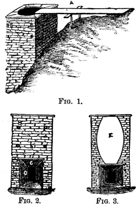
Fig. 1.
Fig. 2. Fig. 3.
A (Fig. 1), Railway Track–B B B, Iron Rods running
through Kiln–C, Capstone over Arch–D, Arch–E,
Well without brick or ash lining.
I send you a description and sketch of a lime-kiln put up on my
premises about five years ago. The dimensions of this kiln are 13
feet square by 25 feet high from foundation, and its capacity 100
bushels in 24 hours. It was constructed of the limestone quarried
on the spot. It has round iron rods (shown in sketch) passing
through, with iron plates fastened to the ends as clamps to make it
more firm; the pair nearest the top should be not less than 2 feet
from that point, the others interspersed about 2 feet apart–the
greatest strain being near the top. The arch should be 7 feet high
by 5½ wide in front, with a gather on the top and sides of
about 1 foot, with plank floor; and if this has a little incline it
will facilitate shoveling the lime when drawn. The arch should have
a strong capstone; also one immediately under the well of the kiln,
with a hole 2 feet in diameter to draw the lime through; or two may
be used with semicircle cut in each. Iron bars 2 inches wide by 1/8
inch thick are used in this kiln for closing it, working in slots
fastened to capstone. These slots must be put in before the caps
are laid. When it is desired to draw lime, these bars may be pushed
laterally in the slots, or drawn out entirely, according to
circumstances; 3 bars will be enough. The slots are made of iron
bars 1½ inches wide, with ends rounded and turned up, and
inserted in holes drilled through capstone and keyed above.
The well of the kiln is lined with fire-brick one course thick,
with a stratum of coal ashes three inches thick tamped in between
the brick and wall, which proves a great protection to the wall.
About 2,000 fire-bricks were used. The proprietors of this kiln say
about one-half the lower part of the well might have been lined
with a first quality of common brick and saved some expense and
been just as good. The form of the well shown in Fig. 3 is 7 feet
in diameter in the bilge, exclusive of the lining of brick and
ashes. Experiments in this vicinity have proved this to be the
best, this contraction toward the top being absolutely necessary,
the expansion of the stone by the heat is so great that the lime
cannot be drawn from perpendicular walls, as was demonstrated in
one instance near here, where a kiln was built on that principle.
The kiln, of course, is for coal, and our stone requires about
three-quarters of a ton per 100 bushels of lime, but this, I am
told, varies according to quality, some requiring more than others;
the quantity can best be determined by experimenting; also the
regulation of the heat–if too great it will cause the stones to
melt or run together as it were, or, if too little, they will not
be properly burned. The business requires skill and judgment to run
it successfully.
This kiln is located at the foot of a steep bluff, the top about
level with the top of the kiln, with railway track built of wooden
sleepers, with light iron bars, running from the bluff to the top
of the kiln, and a hand-car makes it very convenient filling the
kiln. Such a location should be had if possible. Your inquirer may
perhaps get some ideas of the principles of a kiln for using
coal. The dimensions may be reduced, if desired. If for
wood, the arch would have to be formed for that, and the
height of kiln reduced.
THE MANUFACTURE OF APPLE JELLY.
[Footnote: From the report of the New York Agricultural
Society.]
Within the county of Oswego, New York, Dewitt C. Peck reports
there are five apple jelly factories in operation. The failure of
the apple crop, for some singular and unexplained reason, does not
extend in great degree to the natural or ungrafted fruit. Though
not so many as common, even of these apples, there are yet enough
to keep these five mills and the numerous cider mills pretty well
employed. The largest jelly factory is located near the village of
Mexico, and as there are some features in regard to this
manufacture peculiar to this establishment which may be new and
interesting, we will undertake a brief description. The factory is
located on the Salmon Creek, which affords the necessary power. A
portion of the main floor, first story, is occupied as a saw mill,
the slabs furnishing fuel for the boiler furnace connected with the
evaporating department. Just above the mill, along the bank of the
pond, and with one end projecting over the water, are arranged
eight large bins, holding from five hundred to one thousand bushels
each, into which the apples are delivered from the teams. The floor
in each of these has a sharp pitch or inclination toward the water
and at the lower end is a grate through which the fruit is
discharged, when wanted, into a trough half submerged in the
pond.
The preparation of the fruit and extraction of the juice
proceeds as follows: Upon hoisting a gate in the lower end of this
trough, considerable current is caused, and the water carries the
fruit a distance of from thirty to one hundred feet, and passes
into the basement of the mill, where, tumbling down a four-foot
perpendicular fall, into a tank, tight in its lower half and
slatted so as to permit the escape of water and impurities in the
upper half, the apples are thoroughly cleansed from all earthy or
extraneous matter. Such is the friction caused by the concussion of
the fall, the rolling and rubbing of the apples together, and the
pouring of the water, that decayed sections of the fruit are ground
off and the rotten pulp passes away with other impurities. From
this tank the apples are hoisted upon an endless chain elevator,
with buckets in the form of a rake-head with iron teeth, permitting
drainage and escape of water, to an upper story of the mill, whence
by gravity they descend to the grater. The press is wholly of iron,
all its motions, even to the turning of the screws, being actuated
by the water power. The cheese is built up with layers inclosed in
strong cotton cloth, which displaces the straw used in olden time,
and serves also to strain the cider. As it is expressed from the
press tank, the cider passes to a storage tank, and thence to the
defecator.
This defecator is a copper pan, eleven feet long and about three
feet wide. At each end of this pan is placed a copper tube three
inches in diameter and closed at both ends. Lying between and
connecting these two, are twelve tubes, also of copper, 1½
inches in diameter, penetrating the larger tubes at equal distances
from their upper and under surfaces, the smaller being parallel
with each other, and 1½ inches apart. When placed in
position, the larger tubes, which act as manifolds, supplying the
smaller with steam, rest upon the bottom of the pan, and thus the
smaller pipes have a space of three-fourths of an inch underneath
their outer surfaces.
The cider comes from the storage tank in a continuous stream
about three-eighths of an inch in diameter. Steam is introduced to
the large or manifold tubes, and from them distributed through the
smaller ones at a pressure of from twenty-five to thirty pounds per
inch. Trap valves are provided for the escape of water formed by
condensation within the pipes. The primary object of the defecator
is to remove all impurities and perfectly clarify the liquid
passing through it. All portions of pomace and other minute
particles of foreign matter, when heated, expand and float in the
form of scum upon the surface of the cider. An ingeniously
contrived floating rake drags off this scum and delivers it over
the side of the pan. To facilitate this removal, one side of the
pan, commencing at a point just below the surface of the cider, is
curved gently outward and upward, terminating in a slightly
inclined plane, over the edge of which the scum is pushed by the
rake into a trough and carried away. A secondary purpose served by
the defecator is that of reducing the cider by evaporation to a
partial sirup of the specific gravity of about 20° Baume. When
of this consistency the liquid is drawn from the bottom and less
agitated portion of the defecator by a siphon, and thence carried
to the evaporator, which is located upon the same framework and
just below the defecator.
The evaporator consists of a separate system of six copper
tubes, each twelve feet long and three inches in diameter. These
are each jacketed or inclosed in an iron pipe of four inches
internal diameter, fitted with steam-tight collars so as to leave
half an inch steam space surrounding the copper tubes. The latter
are open at both ends permitting the admission and egress of the
sirup and the escape of the steam caused by evaporation therefrom,
and are arranged upon the frame so as to have a very slight
inclination downward in the direction of the current, and each
nearly underneath its predecessor in regular succession. Each is
connected by an iron supply pipe, having a steam gauge or indicator
attached, with a large manifold, and that by other pipes with a
steam boiler of thirty horse power capacity. Steam being let on at
from twenty five to thirty pounds pressure, the stream of sirup is
received from the defecator through a strainer, which removes any
impurities possibly remaining into the upper evaporator tube;
passing in a gentle flow through that, it is delivered into a
funnel connected with the next tube below, and so, back and forth,
through the whole system. The sirup enters the evaporator at a
consistency of from 20° to 23° Baume, and emerges from the
last tube some three minutes later at a consistency of from 30°
to 32° Baume, which is found on cooling to be the proper point
for perfect jelly. This point is found to vary one or two degrees,
according to the fermentation consequent upon bruises in handling
the fruit, decay of the same, or any little delay in expressing the
juice from the cheese. The least fermentation occasions the
necessity for a lower reduction. To guard against this, no cheese
is allowed to stand over night, no pomace left in the grater or
vat, no cider in the tank; and further to provide against
fermentation, a large water tank is located upon the roof and
filled by a force pump, and by means of hose connected with this,
each grater, press, vat, tank, pipe, trough, or other article of
machinery used, can be thoroughly washed and cleansed. Hot water,
instead of cider, is sometimes sent through the defecator,
evaporator, etc., until all are thoroughly scalded and purified. If
the saccharometer shows too great or too little reduction, the
matter is easily regulated by varying the steam pressure in the
evaporator by means of a valve in the supply pipe. If boiled cider
instead of jelly is wanted for making pies, sauces, etc., it is
drawn off from one of the upper evaporator tubes according to the
consistency desired; or can be produced at the end of the process
by simply reducing the steam pressure.
As the jelly emerges from the evaporator it is transferred to a
tub holding some fifty gallons, and by mixing a little therein, any
little variations in reduction or in the sweetness or sourness of
the fruit used are equalized. From this it is drawn through
faucets, while hot, into the various packages in which it is
shipped to market. A favorite form of package for family use is a
nicely turned little wooden bucket with cover and bail, two sizes,
holding five and ten pounds respectively. The smaller packages are
shipped in cases for convenience in handling. The present product
of this manufactory is from 1,500 to 1,800 pounds of jelly each day
of ten hours. It is calculated that improvements now in progress
will increase this to something more than a ton per day. Each
bushel of fruit will produce from four to five pounds of jelly,
fruit ripening late in the season being more productive than
earlier varieties. Crab apples produce the finest jelly; sour,
crabbed, natural fruit makes the best looking article, and a
mixture of all varieties gives most satisfactory results as to
flavor and general quality.
As the pomace is shoveled from the finished cheese, it is again
ground under a toothed cylinder, and thence drops into large
troughs, through a succession of which a considerable stream of
water is flowing. Here it is occasionally agitated by raking from
the lower to the upper end of the trough as the current carries it
downward, and the apple seeds becoming disengaged drop to the
bottom into still water, while the pulp floats away upon the
stream. A succession of troughs serves to remove nearly all the
seeds. The value of the apple seeds thus saved is sufficient to pay
the daily wages of all the hands employed in the whole
establishment. The apples are measured in the wagon box, one and a
half cubic feet being accounted a bushel.
This mill ordinarily employs about six men: One general
superintendent, who buys and measures the apples, keeps time books,
attends to all the accounts and the working details of the mill,
and acts as cashier; one sawyer, who manufactures lumber for the
local market and saws the slabs into short lengths suitable for the
furnace; one cider maker, who grinds the apples and attends the
presses; one jelly maker, who attends the defecator, evaporator,
and mixing tub, besides acting as his own fireman and engineer; one
who attends the apple seed troughs and acts as general helper, and
one man-of-all-work to pack, ship and assist whenever needed. The
establishment was erected late in the season of 1880, and
manufactured that year about forty-five tons of jelly, besides
considerable cider exchanged to the farmers for apples, and some
boiled cider.
The price paid for apples in 1880, when the crop was
superabundant, was six to eight cents per bushel; in 1881, fifteen
cents. The proprietor hopes next year to consume 100,000 bushels.
These institutions are important to the farmer in that they use
much fruit not otherwise valuable and very perishable. Fruit so
crabbed and gnarled as to have no market value, and even frozen
apples, if delivered while yet solid, can be used. (Such apples are
placed in the water while frozen, the water draws the frost
sufficiently to be grated, and passing through the press and
evaporator before there is time for chemical change, they are found
to make very good jelly. They are valuable to the consumer by
converting the perishable, cheap, almost worthless crop of the
bearing and abundant years into such enduring form that its
consumption may be carried over to years of scarcity and furnish
healthful food in cheap and pleasant form to many who would
otherwise be deprived; and lastly, they are of great interest to
society, in that they give to cider twice the value for purposes of
food that it has or can have, even to the manufacturer, for use as
a beverage and intoxicant.
IMPROVED GRAPE BAGS.
It stands to reason that were our summers warmer we should be
able to grow grapes successfully on open walls; it is therefore
probable that a new grape bag, the invention of M. Pelletier, 20
Rue de la Banque, Paris, intended to serve a double purpose, viz.,
protecting the fruit and hastening its maturity, will, when it
becomes known, be welcomed in this country. It consists of a square
of curved glass so fixed to the bag that the sun’s rays are
concentrated upon the fruit, thereby rendering its ripening more
certain in addition to improving its quality generally. The glass
is affixed to the bag by means of a light iron wire support. It
covers that portion of it next the sun, so that it increases the
amount of light and warms the grapes without scorching them, a
result due to the convexity of the glass and the layer of air
between it and the bag. M. Pelletier had the idea of rendering
these bags cheaper by employing plain squares instead of curved
ones, but the advantage thus obtained was more than counterbalanced
by their comparative inefficacy. In practice it was found that the
curved squares gave an average of 7° more than the straight
ones, while there was a difference of 10° when the bags alone
were used, thus plainly demonstrating the practical value of the
invention.
Whether these glass-fronted bags would have much value in the
case of grapes grown under glass in the ordinary way is a question
that can only be determined by actual experiment; but where the
vines are on walls, either under glass screens or in the open air,
so that the bunches feel the full force of the sun’s rays, there
can be no doubt as to their utility, and it is probable that by
their aid many of the continental varieties which we do not now
attempt to grow in the open, and which are scarcely worthy of a
place under glass, might be well ripened. At any rate we ought to
give anything a fair trial which may serve to neutralize, if only
in a slight degree, the uncertainty of our summers. As it is, we
have only about two varieties of grapes, and these not the best of
the hardy kinds, as regards flavor and appearance, that ripen out
of doors, and even these do not always succeed. We know next to
nothing of the many really well-flavored kinds which are so much
appreciated in many parts of the Continent. The fact is, our
outdoor culture of grapes offers a striking contrast to that
practiced under glass, and although our comparatively sunless and
moist climate affords some excuse for our shortcomings in this
respect, there is no valid reason for the utter want of good
culture which is to be observed in a general way.
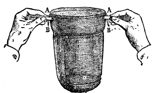
GRAPE BAG.–OPEN.
Given intelligent training, constant care in stopping the
laterals, and checking mildew as well as thinning the berries,
allowing each bunch to get the full benefit of sun and air, and I
believe good eatable grapes would often be obtained even in summers
marked by a low average temperature.
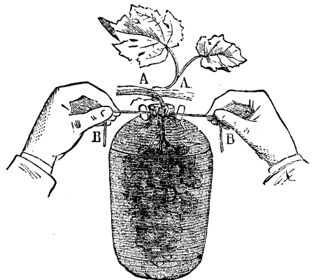
GRAPE BAG.–CLOSED.
If, moreover, to a good system of culture we add some such
mechanical contrivance as that under notice whereby the bunches
enjoy an average warmth some 10° higher than they otherwise
would do, we not only insure the grapes coming to perfection in
favored districts, but outdoor culture might probably be practiced
in higher latitudes than is now practicable.
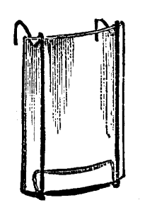
CURVED GLASS FOR FRONT OF BAG.
The improved grape bag would also offer great facilities for
destroying mildew or guarantee the grapes against its attacks, as a
light dusting administered as soon as the berries were fairly
formed would suffice for the season, as owing to the glass
protecting the berries from driving rains, which often accompany
south or south-west winds in summer and autumn, the sulphur would
not be washed off.
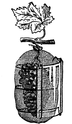
CURVED GLASS FIXED ON BAG.
The inventor claims, and we should say with just reason, that
these glass fronted bags would be found equally serviceable for the
ripening of pears and other choice fruits, and with a view to their
being employed for such a purpose, he has had them made of varying
sizes and shapes. In conclusion, it may be observed that, in
addition to advancing the maturity of the fruits to which they are
applied, they also serve to preserve them from falling to the
ground when ripe.–J. COBNHILL, in the Garden.
UTILIZATION OF SOLAR HEAT.
At a popular fête in the Tuileries Gardens I was struck
with an experiment which seems deserving of the immediate attention
of the English public and military authorities.
Among the attractions of the fête was an apparatus for the
concentration and utilization of solar heat, and, though the sun
was not very brilliant, I saw this apparatus set in motion a
printing machine which printed several thousand copies of a
specimen newspaper entitled the Soleil Journal.
The sun’s rays are concentrated in a reflector, which moves at
the same rate as the sun and heats a vertical boiler, setting the
motive steam-engine at work. As may be supposed, the only object
was to demonstrate the possibility of utilizing the concentrated
heat of the solar rays; but I closely examined it, because the
apparatus seems capable of great utility in existing circumstances.
Here in France, indeed, there is a radical drawback–the sun is
often overclouded.
Thousands of years ago the idea of utilizing the solar rays must
have suggested itself, and there are still savage tribes who know
no other mode of combustion; but the scientific application has
hitherto been lacking. This void this apparatus will fill up. About
fifteen years ago Professor Mouchon, of Tours, began constructing
such an apparatus, and his experiments have been continued by M.
Pifre, who has devoted much labor and expense to realizing M.
Mouchou’s idea. A company has now come to his aid, and has
constructed a number of apparatus of different sizes at a factory
which might speedily turn out a large number of them. It is evident
that in a country of uninterrupted sunshine the boiler might be
heated in thirty or forty minutes. A portable apparatus could boil
two and one-half quarts an hour, or, say, four gallons a day, thus
supplying by distillation or ebullition six or eight men. The
apparatus can be easily carried on a man’s back, and on condition
of water, even of the worst quality, being obtainable, good
drinking and cooking water is insured. M. De Rougaumond, a young
scientific writer, has just published an interesting volume on the
invention. I was able yesterday to verify his statements, for I saw
cider made, a pump set in motion, and coffee made–in short, the
calorific action of the sun superseding that of fuel. The
apparatus, no doubt, has not yet reached perfection, but as it is
it would enable the soldier in India or Egypt to procure in the
field good water and to cook his food rapidly. The invention is of
especial importance to England just now, but even when the Egyptian
question is settled the Indian troops might find it of inestimable
value.
Red tape should for once be disregarded, and a competent
commission forthwith sent to 30 Rue d’Assas, with instructions to
report immediately, for every minute saved may avoid suffering for
Englishmen fighting abroad for their country. I may, of course, be
mistaken, but a commission would decide, and if the apparatus is
good the slightest delay in its adoption would be
deplorable.–Paris Correspondence London Times.
HOW TO ESTABLISH A TRUE MERIDIAN.
[Footnote: A paper read before the Engineers’ Club of
Philadelphia.]
By PROFESSOR L. M. HAUPT.
INTRODUCTORY.
The discovery of the magnetic needle was a boon to mankind, and
has been of inestimable service in guiding the mariner through
trackless waters, and the explorer over desert wastes. In these,
its legitimate uses, the needle has not a rival, but all efforts to
apply it to the accurate determination of permanent boundary lines
have proven very unsatisfactory, and have given rise to much
litigation, acerbity, and even death.
For these and other cogent reasons, strenuous efforts are being
made to dispense, so far as practicable, with the use of the
magnetic needle in surveying, and to substitute therefor the more
accurate method of traversing from a true meridian. This method,
however, involves a greater degree of preparation and higher
qualifications than are generally possessed, and unless the matter
can be so simplified as to be readily understood, it is
unreasonable to expect its general application in practice.
Much has been written upon the various methods of determining,
the true meridian, but it is so intimately related to the
determination of latitude and time, and these latter in turn upon
the fixing of a true meridian, that the novice can find neither
beginning nor end. When to these difficulties are added the
corrections for parallax, refraction, instrumental errors, personal
equation, and the determination of the probable error, he is
hopelessly confused, and when he learns that time may be sidereal,
mean solar, local, Greenwich, or Washington, and he is referred to
an ephemeris and table of logarithms for data, he becomes lost in
“confusion worse confounded,” and gives up in despair, settling
down to the conviction that the simple method of compass surveying
is the best after all, even if not the most accurate.
Having received numerous requests for information upon the
subject, I have thought it expedient to endeavor to prepare a
description of the method of determining the true meridian which
should be sufficiently clear and practical to be generally
understood by those desiring to make use of such information.
This will involve an elementary treatment of the subject,
beginning with the
DEFINITIONS.
The celestial sphere is that imaginary surface upon which
all celestial objects are projected. Its radius is infinite.
The earth’s axis is the imaginary line about which it
revolves.
The poles are the points in which the axis pierces the
surface of the earth, or of the celestial sphere.
A meridian is a great circle of the earth cut out by a
plane passing through the axis. All meridians are therefore north
and south lines passing through the poles.
From these definitions it follows that if there were a star
exactly at the pole it would only be necessary to set up an
instrument and take a bearing to it for the meridian. Such not
being the case, however, we are obliged to take some one of the
near circumpolar stars as our object, and correct the observation
according to its angular distance from the meridian at the time of
observation.
For convenience, the bright star known as Ursæ Minoris or
Polaris, is generally selected. This star apparently revolves about
the north pole, in an orbit whose mean radius is 1° 19′ 13″,[1]
making the revolution in 23 hours 56 minutes.
[Footnote 1: This is the codeclination as given in the Nautical
Almanac. The mean value decreases by about 20 seconds each
year.]
During this time it must therefore cross the meridian twice,
once above the pole and once below; the former is called the
upper, and the latter the lower meridian transit or
culmination. It must also pass through the points farthest east
and west from the meridian. The former is called the eastern
elongation, the latter the western.
An observation may he made upon Polaris at any of these four
points, or at any other point of its orbit, but this latter case
becomes too complicated for ordinary practice, and is therefore not
considered.
If the observation were made upon the star at the time of its
upper or lower culmination, it would give the true meridian at
once, but this involves a knowledge of the true local time of
transit, or the longitude of the place of observation, which is
generally an unknown quantity; and moreover, as the star is then
moving east or west, or at right angles to the place of the
meridian, at the rate of 15° of arc in about one hour, an error
of so slight a quantity as only four seconds of time would
introduce an error of one minute of arc. If the observation be
made, however, upon either elongation, when the star is moving up
or down, that is, in the direction of the vertical wire of the
instrument, the error of observation in the angle between it and
the pole will be inappreciable. This is, therefore, the best
position upon which to make the observation, as the precise time of
the elongation need not be given. It can be determined with
sufficient accuracy by a glance at the relative positions of the
star Alioth, in the handle of the Dipper, and Polaris (see Fig. 1).
When the line joining these two stars is horizontal or nearly so,
and Alioth is to the west of Polaris, the latter is at its
eastern elongation, and vice versa, thus:
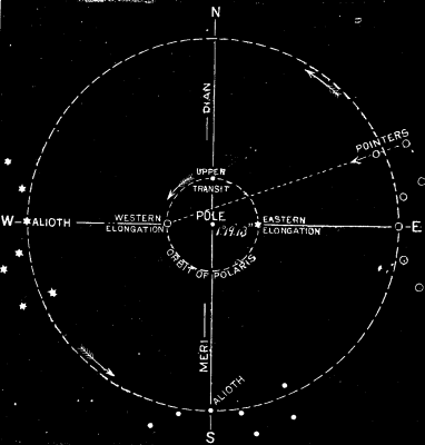
But since the star at either elongation is off the meridian, it
will be necessary to determine the angle at the place of
observation to be turned off on the instrument to bring it into the
meridian. This angle, called the azimuth of the pole star, varies
with the latitude of the observer, as will appear from Fig 2, and
hence its value must be computed for different latitudes, and the
surveyor must know his latitude before he can apply it. Let
N be the north pole of the celestial sphere; S, the position of
Polaris at its eastern elongation; then N S=1° 19′ 13″, a
constant quantity. The azimuth of Polaris at the latitude 40°
north is represented by the angle N O S, and that at 60° north,
by the angle N O’ S, which is greater, being an exterior angle of
the triangle, O S O. From this we see that the azimuth varies at
the latitude.
We have first, then, to find the latitude of the place of
observation.
Of the several methods for doing this, we shall select the
simplest, preceding it by a few definitions.
A normal line is the one joining the point directly
overhead, called the zenith, with the one under foot called
the nadir.
The celestial horizon is the intersection of the
celestial sphere by a plane passing through the center of the earth
and perpendicular to the normal.
A vertical circle is one whose plane is perpendicular to
the horizon, hence all such circles must pass through the normal
and have the zenith and nadir points for their poles. The
altitude of a celestial object is its distance above the
horizon measured on the arc of a vertical circle. As the distance
from the horizon to the zenith is 90°, the difference, or
complement of the altitude, is called the zenith
distance, or co-altitude.
The azimuth of an object is the angle between the
vertical plane through the object and the plane of the meridian,
measured on the horizon, and usually read from the south point, as
0°, through west, at 90, north 180°, etc., closing on south
at 0° or 360°.
These two co-ordinates, the altitude and azimuth, will determine
the position of any object with reference to the observer’s place.
The latter’s position is usually given by his latitude and
longitude referred to the equator and some standard meridian as
co-ordinates.
The latitude being the angular distance north or south of
the equator, and the longitude east or west of the assumed
meridian.
We are now prepared to prove that the altitude of the pole is
equal to the latitude of the place of observation.
Let H P Z Q¹, etc., Fig. 2, represent a meridian section of
the sphere, in which P is the north pole and Z the place of
observation, then H H¹ will be the horizon, Q Q¹ the
equator, H P will be the altitude of P, and Q¹ Z the latitude
of Z. These two arcs are equal, for H C Z = P C Q¹ = 90°,
and if from these equal quadrants the common angle P C Z be
subtracted, the remainders H C P and Z C Q¹, will be
equal.
To determine the altitude of the pole, or, in other
words, the latitude of the place.
Observe the altitude of the pole star when on the
meridian, either above or below the pole, and from this
observed altitude corrected for refraction, subtract the distance
of the star from the pole, or its polar distance, if it was
an upper transit, or add it if a lower. The result will be the
required latitude with sufficient accuracy for ordinary
purposes.
The time of the star’s being on the meridian can be determined
with sufficient accuracy by a mere inspection of the heavens. The
refraction is always negative, and may be taken from the
table appended by looking up the amount set opposite the observed
altitude. Thus, if the observer’s altitude should be 40° 39′
the nearest refraction 01′ 07″, should be subtracted from 40°
37′ 00″, leaving 40° 37′ 53″ for the latitude.
TO FIND THE AZIMUTH OF POLARIS.
As we have shown the azimuth of Polaris to be a function of the
latitude, and as the latitude is now known, we may proceed to find
the required azimuth. For this purpose we have a right-angled
spherical triangle, Z S P, Fig. 4, in which Z is the place of
observation, P the north pole, and S is Polaris. In this triangle
we have given the polar distance, P S = 10° 19′ 13″; the angle
at S = 90°; and the distance Z P, being the complement of the
latitude as found above, or 90°–L. Substituting these in the
formula for the azimuth, we will have sin. Z = sin. P S / sin P Z
or sin. of Polar distance / sin. of co-latitude, from which, by
assuming different values for the co-latitude, we compute the
following table:
An analysis of this table shows that the azimuth this year
(1882) increases with the latitude from 1° 28′ 05″ at 26°
north, to 2° 3′ 11″ at 50° north, or 35′ 06″. It also shows
that the azimuth of Polaris at any one point of observation
decreases slightly from year to year. This is due to the increase
in declination, or decrease in the star’s polar distance. At
26° north latitude, this annual decrease in the azimuth is
about 22″, while at 50° north, it is about 30″. As the
variation in azimuth for each degree of latitude is small, the
table is only computed for the even numbered degrees; the
intermediate values being readily obtained by interpolation. We see
also that an error of a few minutes of latitude will not affect the
result in finding the meridian, e.g., the azimuth at 40° north
latitude is 1° 43′ 21″, that at 41° would be 1° 44′
56″, the difference (01′ 35″) being the correction for one degree
of latitude between 40° and 41°. Or, in other words, an
error of one degree in finding one’s latitude would only introduce
an error in the azimuth of one and a half minutes. With ordinary
care the probable error of the latitude as determined from the
method already described need not exceed a few minutes, making the
error in azimuth as laid off on the arc of an ordinary transit
graduated to single minutes, practically zero.
REFRACTION TABLE FOR ANY ALTITUDE WITHIN THE LATITUDE OF THE
UNITED STATES.
APPLICATIONS.
In practice to find the true meridian, two observations must be
made at intervals of six hours, or they may be made upon different
nights. The first is for latitude, the second for azimuth at
elongation.
To make either, the surveyor should provide himself with a good
transit with vertical arc, a bull’s eye, or hand lantern, plumb
bobs, stakes, etc.[1] Having “set up” over the point through which
it is proposed to establish the meridian, at a time when the line
joining Polaris and Alioth is nearly vertical, level the telescope
by means of the attached level, which should be in adjustment, set
the vernier of the vertical arc at zero, and take the reading. If
the pole star is about making its upper transit, it will
rise gradually until reaching the meridian as it moves westward,
and then as gradually descend. When near the highest part of its
orbit point the telescope at the star, having an assistant to hold
the “bull’s eye” so as to reflect enough light down the tube from
the object end to illumine the cross wires but not to obscure the
star, or better, use a perforated silvered reflector, clamp the
tube in this position, and as the star continues to rise keep the
horizontal wire upon it by means of the tangent screw until
it “rides” along this wire and finally begins to fall below it.
Take the reading of the vertical arc and the result will be the
observed altitude.
[Footnote 1: A sextant and artificial horizon may be used to
find the altitude of a star. In this case the observed angle
must be divided by 2.]
ANOTHER METHOD.
It is a little more accurate to find the altitude by taking the
complement of the observed zenith distance, if the vertical arc has
sufficient range. This is done by pointing first to Polaris when at
its highest (or lowest) point, reading the vertical arc, turning
the horizontal limb half way around, and the telescope over to get
another reading on the star, when the difference of the two
readings will be the double zenith distance, and half
of this subtracted from 90° will be the required altitude. The
less the time intervening between these two pointings, the more
accurate the result will be.
Having now found the altitude, correct it for refraction by
subtracting from it the amount opposite the observed altitude, as
given in the refraction table, and the result will be the latitude.
The observer must now wait about six hours until the star is at its
western elongation, or may postpone further operations for some
subsequent night. In the meantime he will take from the azimuth
table the amount given for his date and latitude, now determined,
and if his observation is to be made on the western elongation, he
may turn it off on his instrument, so that when moved to zero,
after the observation, the telescope will be brought into
the meridian or turned to the right, and a stake set by means of a
lantern or plummet lamp.
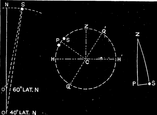
It is, of course, unnecessary to make this correction at the
time of observation, for the angle between any terrestrial object
and the star may be read and the correction for the azimuth of the
star applied at the surveyor’s convenience. It is always well to
check the accuracy of the work by an observation upon the other
elongation before putting in permanent meridian marks, and care
should be taken that they are not placed near any local
attractions. The meridian having been established, the magnetic
variation or declination may readily be found by setting an
instrument on the meridian and noting its bearing as given by the
needle. If, for example, it should be north 5° east, the
variation is west, because the north end of the needle is
west of the meridian, and vice versa.
Local time may also be readily found by observing the
instant when the sun’s center[1] crosses the line, and correcting
it for the equation of time as given above–the result is the true
or mean solar time. This, compared with the clock, will show the
error of the latter, and by taking the difference between the local
lime of this and any other place, the difference of longitude is
determined in hours, which can readily be reduced to degrees by
multiplying by fifteen, as 1 h. = 15°.
[Footnote 1: To obtain this time by observation, note the
instant of first contact of the sun’s limb, and also of last
contact of same, and take the mean.]
APPROXIMATE EQUATION OF TIME.
THE OCELLATED PHEASANT.
The collections of the Museum of Natural History of Paris have
just been enriched with a magnificent, perfectly adult specimen of
a species of bird that all the scientific establishments had put
down among their desiderata, and which, for twenty years past, has
excited the curiosity of naturalists. This species, in fact, was
known only by a few caudal feathers, of which even the origin was
unknown, and which figured in the galleries of the Jardin des
Plantes under the name of Argus ocellatus. This name was
given by J. Verreaux, who was then assistant naturalist at the
museum. It was inscribed by Prince Ch. L. Bonaparte, in his
Tableaux Paralléliques de l’Ordre des Gallinaces, as
Argus giganteus, and a few years later it was reproduced by
Slater in his Catalogue of the Phasianidæ, and by Gray is his
List of the Gallinaceæ. But it was not till 1871 and 1872
that Elliot, in the Annals and Magazine of Natural History, and in
a splendid monograph of the Phasianidæ, pointed out the
peculiarities that were presented by the feathers preserved at the
Museum of Paris, and published a figure of them of the natural
size.
The discovery of an individual whose state of preservation
leaves nothing to be desired now comes to demonstrate the
correctness of Verreaux’s, Bonaparte’s, and Elliot’s suppositions.
This bird, whose tail is furnished with feathers absolutely
identical with those that the museum possessed, is not a peacock,
as some have asserted, nor an ordinary Argus of Malacca, nor an
argus of the race that Elliot named Argus grayi, and which
inhabits Borneo, but the type of a new genus of the family
Phasianidæ. This Gallinacean, in fact, which Mr. Maingonnat
has given up to the Museum of Natural History, has not, like the
common Argus of Borneo, excessively elongated secondaries; and its
tail is not formed of normal rectrices, from the middle of which
spring two very long feathers, a little curved and arranged like a
roof; but it consists of twelve wide plane feathers, regularly
tapering, and ornamented with ocellated spots, arranged along the
shaft. Its head is not bare, but is adorned behind with a tuft of
thread-like feathers; and, finally, its system of coloration and
the proportions of the different parts of its body are not the same
as in the common argus of Borneo. There is reason, then, for
placing the bird, under the name of Rheinardius ocellatus,
in the family Phasianidæ, after the genus Argus which
it connects, after a manner, with the pheasants properly so-called.
The specific name ocellatus has belonged to it since 1871,
and must be substituted for that of Rheinardi.
The bird measures more than two meters in length, three-fourths
of which belong to the tail. The head, which is relatively small,
appears to be larger than it really is, owing to the development of
the piliform tuft on the occiput, this being capable of erection so
as to form a crest 0.05 to 0.06 of a meter in height. The feathers
of this crest are brown and white. The back and sides of the head
are covered with downy feathers of a silky brown and silvery gray,
and the front of the neck with piliform feathers of a ruddy brown.
The upper part of the body is of a blackish tint and the under part
of a reddish brown, the whole dotted with small white or
café-au-lait spots. Analogous spots are found on the
wings and tail, but on the secondaries these become elongated, and
tear-like in form. On the remiges the markings are quite regularly
hexagonal in shape; and on the upper coverts of the tail and on the
rectrices they are accompanied with numerous ferruginous blotches,
some of which are irregularly scattered over the whole surface of
the vane, while others, marked in the center with a blackish spot,
are disposed in series along the shaft and resemble ocelli. This
similitude of marking between the rectrices and subcaudals renders
the distinction between these two kinds of feathers less sharp than
in many other Gallinaceans, and the more so in that two median
rectrices are considerably elongated and assume exactly the aspect
of tail feathers.
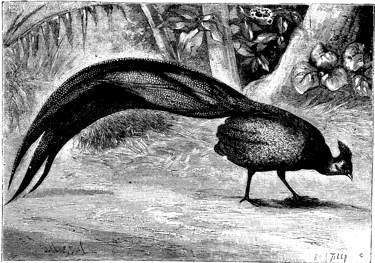
ocellatus).
The true rectrices are twelve in number. They are all absolutely
plane, all spread out horizontally, and they go on increasing in
length from the exterior to the middle. They are quite wide at the
point of insertion, increase in diameter at the middle, and
afterward taper to a sharp point. Altogether they form a tail of
extraordinary length and width which the bird holds slightly
elevated, so as to cause it to describe a graceful curve, and the
point of which touches the soil. The beak, whose upper mandible is
less arched than that of the pheasants, exactly resembles that of
the arguses. It is slightly inflated at the base, above the
nostrils, and these latter are of an elongated-oval form. In the
bird that I have before me the beak, as well as the feet and legs,
is of a dark rose-color. The legs are quite long and are destitute
of spurs. They terminate in front in three quite delicate toes,
connected at the base by membranes, and behind in a thumb that is
inserted so high that it scarcely touches the ground in walking.
This magnificent bird was captured in a portion of Tonkin as yet
unexplored by Europeans, in a locality named Buih-Dinh, 400
kilometers to the south of Hué.–La Nature.
THE MAIDENHAIR TREE.
The Maidenhair tree–Gingkgo biloba–of which we give an
illustration, is not only one of our most ornamental deciduous
trees, but one of the most interesting. Few persons would at first
sight take it to be a Conifer, more especially as it is destitute
of resin; nevertheless, to that group it belongs, being closely
allied to the Yew, but distinguishable by its long-stalked,
fan-shaped leaves, with numerous radiating veins, as in an
Adiantum. These leaves, like those of the larch but unlike most
Conifers, are deciduous, turning of a pale yellow color before they
fall. The tree is found in Japan and in China, but generally in the
neighborhood of temples or other buildings, and is, we believe,
unknown in a truly wild state. As in the case of several other
trees planted in like situations, such as Cupressus funebris, Abies
fortunei, A. kæmpferi, Cryptomeria japonica, Sciadopitys
verticillata, it is probable that the trees have been introduced
from Thibet, or other unexplored districts, into China and Japan.
Though now a solitary representative of its genus, the Gingkgo was
well represented in the coal period, and also existed through the
secondary and tertiary epochs, Professor Heer having identified
kindred specimens belonging to sixty species and eight genera in
fossil remains generally distributed through the northern
hemisphere. Whatever inference we may draw, it is at least certain
that the tree was well represented in former times, if now it be
the last of its race. It was first known to Kæmpfer in 1690,
and described by him in 1712, and was introduced into this country
in the middle of the eighteenth century. Loudon relates a curious
tale as to the manner in which a French amateur became possessed of
it. The Frenchman, it appears, came to England, and paid a visit to
an English nurseryman, who was the possessor of five plants, raised
from Japanese seeds. The hospitable Englishman entertained the
Frenchman only too well. He allowed his commercial instincts to be
blunted by wine, and sold to his guest the five plants for the sum
of 25 guineas. Next morning, when time for reflection came, the
Englishman attempted to regain one only of the plants for the same
sum that the Frenchman had given for all five, but without avail.
The plants were conveyed to France, where as each plant had cost
about 40 crowns, ecus, the tree got the name of arbre a
quarante ecus. This is the story as given by Loudon, who tells
us that Andre Thouin used to relate the fact in his lectures at the
Jardin des Plantes, whether as an illustration of the perfidy of
Albion is not stated.
The tree is dioecious, bearing male catkins on one plant, female
on another. All the female trees in Europe are believed to have
originated from a tree near Geneva, of which Auguste Pyramus de
Candolle secured grafts, and distributed them throughout the
Continent. Nevertheless, the female tree is rarely met with, as
compared with the male; but it is quite possible that a tree which
generally produces male flowers only may sometimes bear female
flowers only. We have no certain evidence of this in the case of
the Gingkgo, but it is a common enough occurrence in other
dioecious plants, and the occurrence of a fruiting specimen near
Philadelphia, as recently recorded by Mr. Meehan, may possibly be
attributed to this cause.
The tree of which we give a figure is growing at Broadlands,
Hants, and is about 40 feet in height, with a trunk that measures 7
feet in girth at 3 feet from the ground, with a spread of branches
measuring 45 feet. These dimensions have been considerably exceeded
in other cases. In 1837 a tree at Purser’s Cross measured 60 feet
and more in height. Loudon himself had a small tree in his garden
at Bayswater on which a female branch was grafted. It is to be
feared that this specimen has long since perished.
We have already alluded to its deciduous character, in which it
is allied to the larch. It presents another point of resemblance
both to the larch and the cedar in the short spurs upon which both
leaves and male catkins are borne, but these contracted branches
are mingled with long extension shoots; there seems, however, no
regular alternation between the short and the long shoots, at any
rate the rationale of their production is not understood,
though in all probability a little observation of the growing plant
would soon clear the matter up.
The fruit is drupaceous, with a soft outer coat and a hard woody
shell, greatly resembling that of a Cycad, both externally and
internally. Whether the albumen contains the peculiar “corpuscles”
common to Cycads and Conifers, we do not for certain know, though
from the presence of 2 to 3 embryos in one seed, as noted by
Endlicher, we presume this is the case. The interest of these
corpuscles, it may be added, lies in the proof of affinity they
offer between Conifers and the higher Cryptogams, such as ferns and
lycopods–an affinity shown also in the peculiar venation of the
Gingkgo. Conifers are in some degree links between ordinary
flowering plants and the higher Cryptogams, and serve to connect in
genealogical sequence groups once considered quite distinct. In
germination the two fleshy cotyledons of the Gingkgo remain within
the shell, leaving the three-sided plumule to pass upward; the
young stem bears its leaves in threes.
We have no desire to enter further upon the botanical
peculiarities of this tree; enough if we have indicated in what its
peculiar interest consists. We have only to add that in gardens
varieties exist some with leaves more deeply cut than usual, others
with leaves nearly entire, and others with leaves of a
golden-yellow color.–Gardeners’ Chronicle.
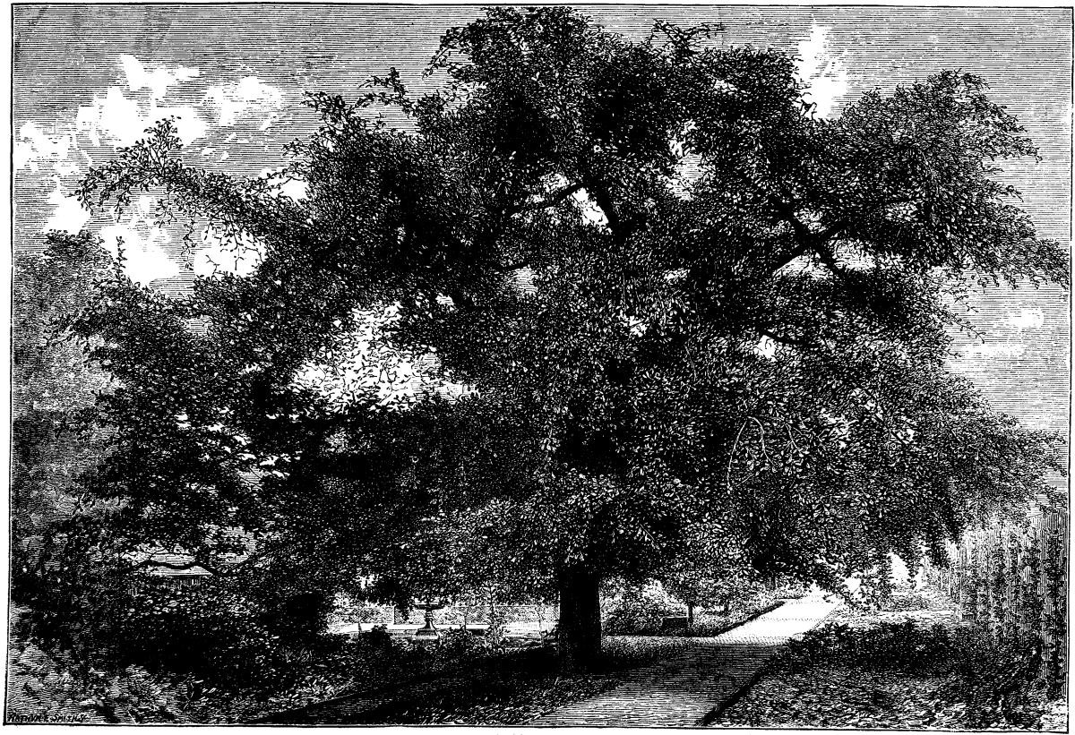
THE MAIDENHAIR TREE IN THE GARDENS AT
BROADLANDS.
THE WOODS OF AMERICA.
A collection of woods without a parallel in the world is now
being prepared for exhibition by the Directors of the American
Museum of Natural History. Scattered about the third floor of the
Arsenal, in Central Park, lie 394 logs, some carefully wrapped in
bagging, some inclosed in rough wooden cases, and others partially
sawn longitudinally, horizontally, and diagonally. These logs
represent all but 26 of the varieties of trees indigenous to this
country, and nearly all have a greater or less economic or
commercial value. The 26 varieties needed to complete the
collection will arrive before winter sets in, a number of specimens
being now on their way to this city from the groves of California.
Mr. S. D. Dill and a number of assistants are engaged in preparing
the specimens for exhibition. The logs as they reach the workroom
are wrapped in bagging and inclosed in cases, this method being
used so that the bark, with its growth of lichens and delicate
exfoliations, shall not be injured while the logs are in process of
transportation from various parts of the country to this city. The
logs are each 6 feet in length, and each is the most perfect
specimen of its class that could be found by the experts employed
in making the collection. With the specimens of the trees come to
the museum also specimens of the foliage and the fruits and flowers
of the tree. These come from all parts of the Union–from Alaska on
the north to Texas on the south, from Maine on the east to
California on the west–and there is not a State or Territory in
the Union which has not a representative in this collection of
logs. On arrival here the logs are green, and the first thing in
the way of treatment after their arrival is to season them, a work
requiring great care to prevent them from “checking,” as it is
technically called, or “season cracking,” as the unscientific term
the splitting of the wood in radiating lines during the seasoning
process. As is well known, the sap-wood of a tree seasons much more
quickly than does the heart of the wood. The prevention of this
splitting is very necessary in preparing these specimens for
exhibition, for when once the wood has split its value for dressing
for exhibition is gone. A new plan to prevent this destruction of
specimens is now being tried with some success under the direction
of Prof. Bickmore, superintendent of the museum. Into the base of
the log and alongside the heart a deep hole is bored with an auger.
As the wood seasons this hole permits of a pressure inward and so
has in many instances doubtless saved valuable specimens. One of
the finest in the collection, a specimen of the persimmon tree,
some two feet in diameter, has been ruined by the seasoning
process. On one side there is a huge crack, extending from the top
to the bottom of the log, which looks as though some amateur
woodman had attempted to split it with an ax and had made a poor
job of it. The great shrinking of the sap-wood of the persimmon
tree makes the wood of but trifling value commercially. It also has
a discouraging effect upon collectors, as it is next to impossible
to cure a specimen, so that all but this one characteristic of the
wood can be shown to the public in a perfect form.
Before the logs become thoroughly seasoned, or their lines of
growth at all obliterated, a diagram of each is made, showing in
accordance with a regular scale the thickness of the bark, the
sap-wood, and the heart. There is also in this diagram a scale
showing the growth of the tree during each year of its life, these
yearly growths being regularly marked about the heart of the tree
by move or less regular concentric circles, the width of which
grows smaller and smaller as the tree grows older. In this
connection attention may be called to a specimen in the collection
which is considered one of the most remarkable in the world. It is
not a native wood, but an importation, and the tree from which this
wonderful slab is cut is commonly known as the “Pride of India.”
The heart of this particular tree was on the port side, and between
it and the bark there is very little sap-wood, not more than an
inch. On the starbord side, so to speak, the sap-wood has grown out
in an abnormal manner, and one of the lines indicative of a year’s
growth is one and seven-eighths inches in width, the widest growth,
many experts who have seen the specimen say, that was ever
recorded. The diagrams referred to are to be kept for scientific
uses, and the scheme of exhibition includes these diagrams as a
part of the whole.
After a log has become seasoned it is carefully sawed through
the center down about one-third of its length. A transverse cut is
then made and the semi-cylindrical section thus severed from the
log is removed. The upper end is then beveled. When a log is thus
treated the inspector can see the lower two-thirds presenting
exactly the same appearance it did when growing in the forest. The
horizontal cut, through the sap-wood and to the center of the
heart, shows the life lines of the tree, and carefully planed as
are this portion, the perpendicular and the beveled sections, the
grain of the wood can thus be plainly seen. That these may be made
even more valuable to the architect and artisan, the right half of
this planed surface will be carefully polished, and the left half
left in the natural state. This portion of the scheme of treatment
is entirely in the interests of architects and artisans, and it is
expected by Prof. Bickmore that it will be the means of securing
for some kinds of trees, essentially of American growth, and which
have been virtually neglected, an important place in architecture
and in ornamental wood-work, and so give a commercial value to
woods that are now of comparatively little value.
Among the many curious specimens in the collection now being
prepared for exhibition, one which will excite the greatest
curiosity is a specimen of the honey locust, which was brought here
from Missouri. The bark is covered with a growth of thorns from one
to four inches in length, sharp as needles, and growing at
irregular intervals. The specimen arrived here in perfect
condition, but, in order that it might be transported without
injury, it had to be suspended from the roof of a box car, and thus
make its trip from Southern Missouri to this city without change.
Another strange specimen in the novel collection is a portion of
the Yucca tree, an abnormal growth of the lily family. The trunk,
about 2 feet in diameter, is a spongy mass, not susceptible of
treatment to which the other specimens are subjected. Its bark is
an irregular stringy, knotted mass, with porcupine-quill-like
leaves springing out in place of the limbs that grow from all
well-regulated trees. One specimen of the yucca was sent to the
museum two years ago, and though the roots and top of the tree were
sawn off, shoots sprang out, and a number of the handsome flowers
appeared. The tree was supposed to be dead and thoroughly seasoned
by this Fall, but now, when the workmen are ready to prepare it for
exhibition, it has shown new life, new shoots have appeared, and
two tufts of green now decorate the otherwise dry and withered log,
and the yucca promises to bloom again before the winter is over.
One of the most perfect specimens of the Douglass spruce ever seen
is in the collection, and is a decided curiosity. It is a recent
arrival from the Rocky Mountains. Its bark, two inches or more in
thickness, is perforated with holes reaching to the-sap-wood. Many
of these contain acorns, or the remains of acorns, which have been
stored there by provident woodpeckers, who dug the holes in the
bark and there stored their winter supply of food. The oldest
specimen in the collection is a section of the Picea
engelmanni, a species of spruce growing in the Rocky Mountains
at a considerable elevation above the sea. The specimen is 24
inches in diameter, and the concentric circles show its age to be
410 years. The wood much resembles the black spruce, and is the
most valuable of the Rocky Mountain growths. A specimen of the nut
pine, whose nuts are used for food by the Indians, is only 15
inches in diameter, and yet its life lines show its age to be 369
years. The largest specimen yet received is a section of the white
ash, which is 46 inches in diameter and 182 years old. The next
largest specimen is a section of the Platanus occidentalis,
variously known in commerce as the sycamore, button-wood, or plane
tree, which is 42 inches in diameter and only 171 years of age.
Specimens of the redwood tree of California are now on their way to
this city from the Yosemite Valley. One specimen, though a small
one, measures 5 feet in diameter and shows the character of the
wood. A specimen of the enormous growths of this tree was not
secured because of the impossibility of transportation and the fact
that there would be no room in the museum for the storage of such a
specimen, for the diameter of the largest tree of the class is 45
feet and 8 inches, which represents a circumference of about 110
feet. Then, too, the Californians object to have the giant trees
cut down for commercial, scientific, or any other purposes.
To accompany these specimens of the woods of America, Mr. Morris
K. Jesup, who has paid all the expense incurred in the collection
of specimens, is having prepared as an accompanying portion of the
exhibition water color drawings representing the actual size,
color, and appearance of the fruit, foliage, and flowers of the
various trees. Their commercial products, as far as they can be
obtained, will also be exhibited, as, for instance, in the case of
the long-leaved pine, the tar, resin, and pitch, for which it is
especially valued. Then, too, in an herbarium the fruits, leaves,
and flowers are preserved as nearly as possible in their natural
state. When the collection is ready for public view next spring it
will be not only the largest, but the only complete one of its kind
in the country. There is nothing like it in the world, as far as is
known; certainly not in the royal museums of England, France, or
Germany.
Aside from the value of the collection, in a scientific way, it
is proposed to make it an adjunct to our educational system, which
requires that teachers shall instruct pupils as to the materials
used for food and clothing. The completeness of the exhibition will
be of great assistance also to landscape gardeners, as it will
enable them to lay out private and public parks so that the most
striking effects of foliage may be secured. The beauty of these
effects can best be seen in this country in our own Central Park,
where there are more different varieties and more combinations for
foliage effects than in any other area in the United States. To
ascertain how these effects are obtained one now has to go to much
trouble to learn the names of the trees. With this exhibition such
information can be had merely by observation, for the botanical and
common names of each specimen will be attached to it. It will also
be of practical use in teaching the forester how to cultivate trees
as he would other crops. The rapid disappearance of many valuable
forest trees, with the increase in demand and decrease in supply,
will tend to make the collection valuable as a curiosity in the not
far distant future as representing the extinct trees of the
country.–N.Y. Times.
A catalogue, containing brief notices of many important
scientific papers heretofore published in the SUPPLEMENT, may be
had gratis at this office.
THE SCIENTIFIC AMERICAN SUPPLEMENT.
PUBLISHED WEEKLY.
Terms of Subscription, $5 a Year.
Sent by mail, postage prepaid, to subscribers in any part of the
United States or Canada. Six dollars a year, sent, prepaid, to any
foreign country.
All the back numbers of THE SUPPLEMENT, from the commencement,
January 1, 1876, can be had. Price, 10 cents each.
All the back volumes of THE SUPPLEMENT can likewise be supplied.
Two volumes are issued yearly. Price of each volume, $2.50,
stitched in paper, or $3.50, bound in stiff covers.
COMBINED RATES–One copy of SCIENTIFIC AMERICAN and one copy of
SCIENTIFIC AMERICAN SUPPLEMENT, one year, postpaid, $7.00.
A liberal discount to booksellers, news agents, and
canvassers.
MUNN & CO., Publishers,
261 Broadway, New York, N. Y.
PATENTS.
In connection with the Scientific American, Messrs. MUNN
& Co. are Solicitors of American and Foreign Patents, have had
35 years’ experience, and now have the largest establishment in the
world. Patents are obtained on the best terms.
A special notice is made in the Scientific American of
all Inventions patented through this Agency, with the name and
residence of the Patentee. By the immense circulation thus given,
public attention is directed to the merits of the new patent, and
sales or introduction often easily effected.
Any person who has made a new discovery or invention can
ascertain, free of charge, whether a patent can probably be
obtained, by writing to MUNN & Co.
We also send free our Hand Book about the Patent Laws, Patents,
Caveats. Trade Marks, their costs, and how procured, with hints for
procuring advances on inventions. Address
MUNN & CO., 261 Broadway, New York.
Branch Office, cor. F and 7th Sts., Washington, D. C.