The cover image was created by the transcriber and is placed in the public domain.
War Department Technical Manual
TM 3-376A
PORTABLE
FLAME THROWER
M2-2

RESTRICTED
DISSEMINATION OF RESTRICTED MATTER. The information contained in
restricted documents and the essential characteristics of restricted
material may be given to any person known to be in the service of the
United States and to persons of undoubted loyalty and discretion who
are cooperating in Government work, but will not be communicated to the
public or to the press except by authorized military public relations
agencies. (See also par. 18b, AR 380-5, 28 Sep 1942.)
War Department – 16 May 1944
Washington, D. C.
WAR DEPARTMENT,
Washington, 25, D. C. 16 May 1944
TM 3-376A, Portable Flame Thrower M2-2 is published for the information
and guidance of all concerned.
[A. G. 300.7 (21 March 44)]
By order of the Secretary of War:
G. C. MARSHALL,
Chief of Staff.
Official:
J. A. ULIO,
Major General,
The Adjutant General.
Distribution:
R & H (5); Bn 2, 7, 17 (2); C & H 3 (5); IC & H 5 (5); C 2, 7, 17 (2);
X. ID: T/O & E 72T, Light Div; 17, Armd Div; IR: T/O 5-192, Hq & Hq Co,
Engr Comb Gr; 5-171, Engr Comb Regt; IBn: T/O 5-15, Engr Comb Bn; 5-35,
Engr Bn Sep; 5-175, Engr Bn, Comb Regt; 5-215, Armd Engr Bn; 5-475T,
Engr Bn, Light Div; IC: T/O 5-16, Hq & Hq & Sv Co, Engr Combat Bn;
5-17, Engr Comb Co; 5-192, Hq & Hq Co, Engr Comb Gr; 5-36, Hq & Hq & Sv
Co, Engr Bn (Sep); 5-37, Co, Engr Bn (Sep); 5-176, Hq & Hq Det, Engr
Bn, Engr Comb Regt; 5-216, Hq & Hq Co, Armd Engr Bn; 5-217, Co, Armd
Engr Bn; 5-476T, Hq & Hq Co, Engr Bn, Light Div; 5477-T, Co, Engr Bn,
Light Div.
(For explanation of symbols see Par 26, FM 21-6)
TECHNICAL MANUAL
PORTABLE FLAME THROWER M2-2
WAR DEPARTMENT
Washington, 25, D. C., 16 May 1945
Changes}
No. 1 }
TM 3-376A, 16 May 1944, is changed as follows:
10. ITEMS WITH EACH FLAME THROWER.
**
***
b. Kit, spare parts, for portable flame thrower M2-2, assembly
B81-6-190.
**
***
g. (Added). Army Service Forces Catalog CW 7-440114, Organizational
Spare Parts and Equipment: 1st and 2d Echelons: for Flame Thrower,
Portable, M2-2.
Fig. 8. Contents of tool kit:
**
***
B. 1 Wrench, hex, * * * set screws, H22-49-12.
2 Wrench, hex, 5/32-inch across flats for 5/16-inch socket-head
set screws, H22-49-140.
**
***
Fig 9. Contents of spare parts kit:
F. (Added). 3 Tubes, deflector, A81-1-501. (See fig. 39.)
G. (Added). 3 Locknuts, pipe, hex, 1/8-inch, H98-5-382 (for use
with deflector tube). (See fig. 39.)
H. (Added). 1 Support, diaphragm, A81-1-428. (See fig. 47.)
12. NEW EQUIPMENT.
**
***
m. (Added). New gun may be received with valve spring removed from
barrel and valve assembly. Spring comes tied to barrel. This is done to
prevent strain on valve diaphragm assembly caused by pressure of spring
in gun during storage and shipment. When weapon is being prepared for
operation, spring must be untied from barrel and installed in gun, as
described in paragraph 75.
n. (Added). Pressure regulator may be shipped at zero adjustment to
prevent possibility of strain on diaphragm during shipment and storage.
A regulator shipped in this condition has a tag (tied to the[2]
tank coupling) stating that the regulator is not set. When weapon is
received in this condition, it must be adjusted as described in paragraph
67 before it can be operated.
*These changes supersede TB 3-376A-1, 19 October 1944.
15. TRAINING.
**
***
b. Use of water in training. Water may be used (instead of fuel)
for elementary practice firing. Ignition cylinders are * * * piece,
and lubricated (Par. 49). Use of water, however, should always be
supplemented by firing ignited fuel because water does not give a
correct impression of stream and flame characteristics.
**
***
17. CONNECTING TANK GROUP AND GUN GROUP.
**
***
a. Place the new * * * to 2 minutes. Slight pressure sometimes
builds up in the fuel tanks, even though the pressure-tank valve has
not been opened, and causes some overflow of fuel when the coupling
plug is removed. This pressure may be relieved by—
(1) Standing the tank group upright.
(2) Slightly opening filling plug on top of fuel tanks to
bleed the pressure.
(3) Closing the opening at filling plug and tightening it
with wrench.
**
***
18. LOADING WITH IGNITION CYLINDER.
**
***
b. Precautions. Care must be * * * front of gun. Do not ignite the
ignition cartridge until the weapon is to be fired at the target.
**
***
30. AFTER FIRING.
When the firer * * * mission, he should:
a. First, remove and discard the ignition cylinder, as
the ignition cylinder should never be present when blowing out fuel
or after blowing out fuel except when preparing for a new mission. To
remove cylinder, proceed as follows:
**
***
b. Close the pressure-tank valve by turning valve handle clockwise
(to conserve remaining pressure in pressure tank) only if additional
shots are to be fired before refilling and recharging.
c. If no additional shots are to be fired before refilling
and recharging, open pressure-tank valve by turning handle
counterclockwise. Point the gun away from personnel and blow out
the remaining fuel and pressure, if any, from the fuel tanks by
squeezing the valve lever and grip safety until there is no further
discharge. The trigger should not be used during this operation.
Then close the pressure-tank valve to prevent entrance of foreign
matter into the pressure system.
d. (Superseded). Carefully remove tank group from the back. This may
be done most easily by sitting or squatting with back to a tree stump,
flat rock, packing box, or other object. Release the body and shoulder
straps and ease tank group off the back. Avoid dropping equipment on
the ground as this may damage it.
**
***
31. IGNITION CYLINDER.
**
***
c. Packing. Ignition cylinders are * * * each flame thrower. Fifty
cans (100 ignition cylinders) are contained in each ignition
cylinder packing box. Wooden packing box with contents weighs
approximately 50 to 55 pounds. Outside dimensions of the box are
approximately 16-1/4 inches by 14-3/4 inches by 10-1/4 inches. Cubage
is 1-3/12 cubic feet.
**
***
32. CHARGING PRESSURE TANK.
**
***
b. Charging from air compressor. Compressor, air, gasoline * * *
cylinders as well. Instructions for use of the compressor will be found
in TM 3-377.
**
***
Figure 23. Charging two pressure tanks, using charging and filling
lines, and cylinders of compressed air or nitrogen. As many as four
pressure tank and valve assemblies, on or off tank groups, can be
charged at one time from cylinders coupled as shown in figure 24.
33. PRECAUTIONS WHEN PRESSURE-CHARGING.
**
***
m. (Added). Inspect carefully to be certain that no traces of
grease, flame thrower fuel, oil, dirt, or other foreign matter are present
in flame thrower pressure tanks, outlets of air compressor, connections,
hose, or cylinders containing compressed air.
n. (Added). Hands and tools must be free of oil or grease when
charging or servicing flame thrower pressure systems.
o. (Added). Discharge any remaining compressed air in flame
thrower pressure tanks before recharging.
p. (Added). If compressed air is to be used, and if any grease,
oil, or flame thrower fuel is detected by sense of smell or sight
within pressure tank and valve assemblies or cylinders, return tanks
or cylinders for cleaning to the appropriate third-echelon maintenance
agency of Chemical Warfare Service.
35.1 PEPTIZED FUELS (Added).
a. Characteristics.
(1) Pour more readily than usual thickened
fuels.
(2) Give a larger diameter flame than thickened fuels.
(3) Give longer effective ranges than liquid fuels.
(4) Prepared more quickly in cool temperatures than thickened
fuels.
b. Preparation.
(1) Open 5-1/4-pound can or cans of thickener.
(2) Add 2 mess kit spoonfuls of water to each can of thickener. Stir
until the water disappears in the thickener. It is not necessary to mix
the water uniformly with all of the thickener.
(3) Proceed at once as directed in paragraph 35. Avoid accidental
addition of any water to the thickener or fuel other than that stated
in (2) above.
(4) Peptized fuels set a little more quickly than the usual thickened
fuels, but their general appearance after setting is the same. After
standing, however, peptized fuels spontaneously become thinner and
may be poured without use of pressure. The time it takes for thinning
to occur depends on the temperature of the fuel. At 75° Fahrenheit or
higher, thinning occurs in approximately 1 to 2 hours. At temperatures
below 60° Fahrenheit, thinning occurs several days after preparation of
the peptized fuel.
(5) If water has accidentally gotten into fuel before addition of
the thickener, peptizing action takes place, but the results are
unpredictable because the quantity of water added is not controlled.
36. PREPARATION OF LIQUID FUELS.
a. Choice of ingredients. Thin fuels are * * * reaching the target.
For this reason, liquid fuels should contain the lowest proportion of
gasoline and the highest proportion of heavier fuels that permit easy
ignition. In hot climates, * * * of great importance. The gasoline
used can be any U. S. grade of motor fuel or aviation gasoline.
Suitable blends are as follows:
**
***
(3) (Added). By volume, 20 to 25 percent gasoline and 75 to 80
percent light fuel oil.
**
***
40.1 USE OF PACKBOARDS (Added).
Detachable pressure tank and valve assemblies (par. 66.1) make possible
the use of packboards for transporting pressure tanks, 5-gallon
cans of fuel, wrenches, and additional ignition cylinders close to the
front line of combat to troops using flame throwers. As packboards
are not manufactured specifically for servicing flame throwers, standard
quartermaster-issue packboards are used. Packboard transportation
is practicable only with pourable fuel. (Pourable fuels include
some thickened fuels and all liquid fuels.)
a. The following is a suggested procedure for packboard transportation:
(1) Lash all necessary filling and charging supplies for one flame
thrower to packboard, using lashing rope and straps.
(2) Tie one pressure tank and valve assembly to top of one flat 5-gallon
fuel can so that flexible shaft and handle hang down parallel to
one side of the fuel can.
(3) Carry wrench with large enough opening to unscrew filling
plugs from tops of fuel tanks and to tighten plugs after filling.
(4) Carry extra ignition cylinders.
b. Return empty pressure tank and valve assembly along with empty
fuel can and wrench on packboard to flame thrower servicing point.
c. If a supply of flame thrower tank groups is available, they may
be preferred to the packboard method of transportation. Tank
groups are easy to carry, and a filled and charged tank group can
replace an emptied one as quickly as packboard method can be used to
service flame thrower.
**
***
48. SERVICE KIT.
**
***
a. Tools.
**
***
1 Screw driver, common, * * * blade diameter, H22-50-6.
(Fig. 8.)
2 Wrenches, hex, 5/32 inch across flats (for 5/16-inch socket-head
set screws), H22-49-140. (See B, fig. 8.)
2 Wrenches, hex, * * * set screws), H22-49-91.
**
***
b. Accessories and spare parts.
**
***
1 Tank and valve, pressure, assembly (less valve shaft assembly,
B81-1-883) B81-1-879. (See fig. 35.2.)
1 Shaft, valve, assembly B-81-1-883. (See fig. 35.2.)
2 Case, spring, assemblies B81-1-444. (Fig. 9.)
**
***
1 Regulator, pressure, assembly (Grove type) B81-1-778.
(Fig. 35.2.)
1 Compound, anti-seize, white * * * 1/4-pound can, H99-3-12.
2 Gages, pressure * * * assembly B81-6-90. (Fig. 32.)
6 Tubes, deflector, A81-1-501. (See fig. 39.)
6 Locknuts, pipe, hex, 1/8-inch, H98-5-382. (See fig. 39.)
2 Supports, diaphragm, A81-1-428. (See fig. 47.)
6 Springs, R81-1-922 (for socket). (See fig. 35.8.)
6 Washers, backing, R81-1-924 (brass washer for socket).
(See fig. 35.8.)
12 Washers, B81-1-923 (synthetic rubber washer for
socket). (See fig. 35.8.)
6 Caps, plug, B81-1-926 (with chain) (dust cap for plug).
(See fig. 35.3.)
12 Nuts, wing, A81-1-877. (See fig. 35.4.)
2 Army Service Forces Catalogs CW 6-445115, Sets of Tools,
Equipment, and Similar Material: Kit, service, for Portable
Flame Thrower, M2-2.
2 Army Service Forces Catalogs CW 7-440114, Organizational
Spare Parts and Equipment: 1st and 2d Echelons:
for Flame Thrower, Portable, M2-2.
2 War Department Technical Manuals 3-376A, Portable
Flame Thrower M2-2.
49. LUBRICATION.
a. Gun group.
**
***
(2) Frequency of lubrication. The surfaces of * * * lubricated
before reassembly. Do not soak or wash the spring case
assembly in solvent because this may remove the grease
which is factory packed in the spring case assembly. This
grease cannot be replaced. To clean spring case assembly,
wide outside surfaces with cloth saturated with solvent.
**
***
53. SERVICE WHEN FILLING AND CHARGING.
**
***
d. Testing for leaks in pressure system. After charging and
* * * to test pressure. (Fig. 32.) To install gage, unscrew
check-valve cap, moisten end of check valve with water or saliva,
and screw gage in check-valve body. Use of water or saliva as
lubricant prevents cutting of the rubber washer by the check
valve. If pressure has * * * and then retested.
66. PRESSURE TANK AND VALVE ASSEMBLY.
a. Description and functioning. The pressure tank * * * assembly
(Fig. 33) includes:
(1) Pressure tank. The pressure tank * * * the fuel tanks.
The pressure-tank clamp may be adjusted to different outside
diameters of pressure tanks by means of a nut and screw
tightening device (fig. 35.1) or by means of a stepped ring at
end of clamp.
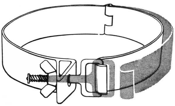
Figure 35.1. (Added.) Adjustable pressure tank clamp, showing use of nut and
screw tightening device.
**
***
b. Removal. (Fig. 33.)
**
***
(2) Removal procedure.
**
***
(h) (Added). To remove check valve, unscrew check valve cap and
check valve body, using wrenches.
c. Installation. (Figs. 33 and 39.)
**
***
(7) (Added). To install check valve, apply thread compound
lightly to threads of cheek valve body and screw into opening in pressure-tank
valve. Tighten check valve body in position, using wrench.
Screw check valve cap on check valve body and tighten with wrench.
**
***
66.1 DETACHABLE PRESSURE TANK AND VALVE ASSEMBLIES
(Added).
Newly developed detachable pressure tank and valve assemblies provide
an improved and speedier method of servicing M2-2 portable flame
throwers in forward combat zones.
a. Description and functioning.
(1) Detachable pressure tank and valve assemblies (figs. 35.2 and
35.3) are used in modified flame throwers. They make it unnecessary to
replace empty complete tank groups with filled and charged complete
tank groups.
(2) Replacement of complete tank group, however, may be preferred when
an extra supply of tank groups is available, or if thickened fuel is
too stringy and viscous to pour.
(3) Detachable pressure tank and valve assemblies can be attached only
to flame throwers which include sockets (figs. 35.2 and 35.3) and
shortened regulator tubes. Flame throwers produced recently include
this design modification.
(4) A plug and cap (fig. 35.3) on detachable pressure tank and valve
assembly replace tube elbow (fig. 33) used on nondetachable pressure
tank and valve assembly.
b. Removal. Care must be taken to prevent damage to connections
during removal and installation. The procedure for removal of pressure
tank and valve assembly is as follows:
(1) Close pressure-tank valve. Press valve lever and safety grip on gun
to release all pressure from fuel system and gun.
(2) Unscrew wing nut from valve flexible shaft. (See fig. 35.4.) Be
careful not to misplace wing nut.
(3) Pull clamp and shaft from stud which is welded on fuel tank.
(4) With one hand under pressure tank, unclamp but do not fully open
pressure-tank clamp.
(5) Supporting pressure tank valve with top of right hand, push knurled
socket in and away from pressure tank valve. Left hand may be placed
at back of regulator tube so that tube does not bend away from socket.
(See fig. 35.5.) Pull out pressure tank and valve assembly.
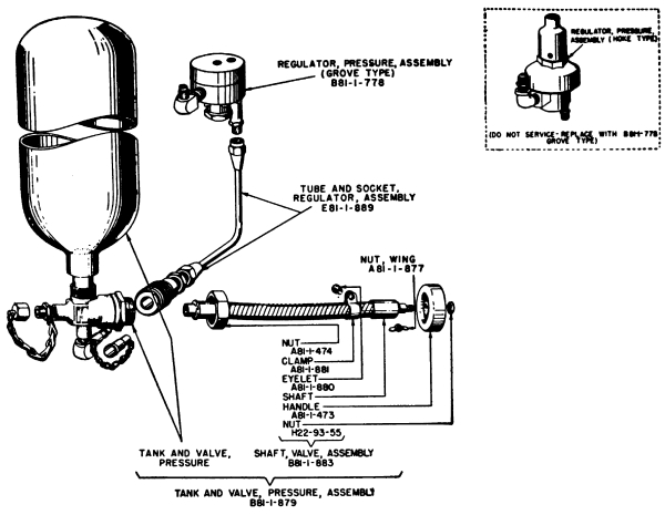
Figure 35.2. (Added.) Pressure system
disassembled, showing removable pressure tank and valve assembly,
nomenclature, and Chemical Warfare Service stock numbers.
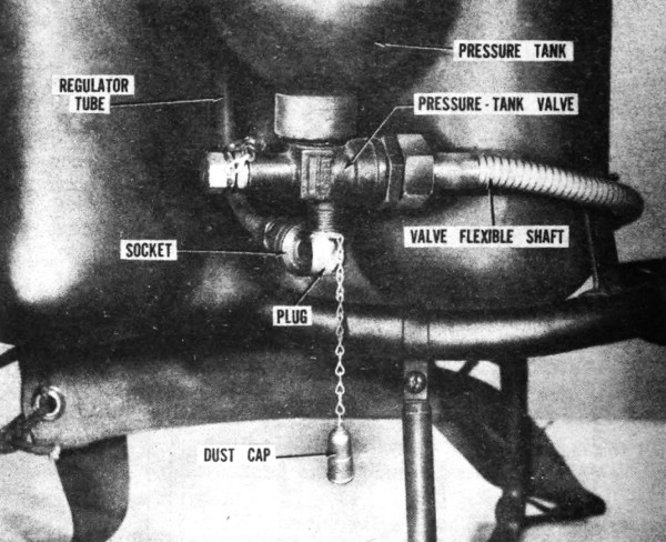
Figure 35.3. (Added.) Detachable pressure tank
and valve assembly, connected to modified regulator tube assembly.
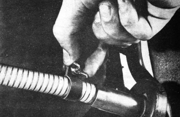
Figure 35.4. (Added.) Removing wing nut to free
valve flexible shaft.
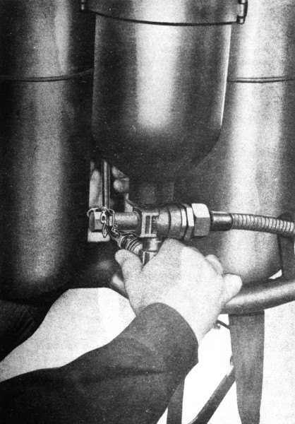
Figure 35.5. (Added.) Pushing knurled socket
away from pressure tank, permitting pressure tank and valve assembly to
be removed from tank group.
(6) Put cap as far as it will go over opening of the plug. (See fig.35.6.)
This prevents dust and other foreign matter from entering empty
pressure tank.
(7) Flame thrower is now ready to receive a charged pressure tank and
valve assembly. (See fig. 35.7.)
c. Installation. To install a charged or replacement detachable
pressure tank and valve assembly, proceed as follows:
(1) Remove dust cap from plug of charged pressure tank and
valve assembly. (Never open pressure-tank valve with cap on plug.)
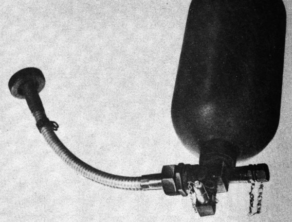
Figure 35.6. (Added.) Pressure tank and valve
assembly with dust cap over plug opening.
(2) Support socket and tube with left hand and insert plug in socket
with right hand. If tube is not supported, it is difficult to lock the
plug in the socket and it is possible that tube may become bent. Press
bottom of tank until plug snaps into socket. Test by attempting to pull
tank and plug from socket. Plug must not pull out; if it does, insert
again and press bottom of tank. Grasp knurled collar of socket and test
for end play. If collar slides freely back and forth on socket, the
connection is not tight and plug should be pressed in farther.
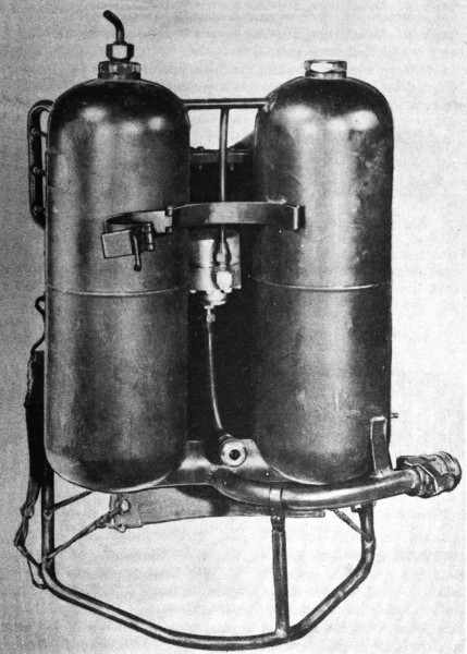
Figure 35.7. (Added.) Tank group, ready to
receive a charged pressure tank and valve assembly.
(3) Replace small clamp (valve-stem clamp) over stud projecting from
fuel tank, and screw wing nut on stud to secure valve flexible shaft in
place. Do not use wrench on wing nut.
d. Maintenance. Follow maintenance instructions given in paragraph
66. In addition, if leaks occur and signs of wear are visible, carry
out the following procedures:
(1) Worn washer. Replace synthetic rubber washer by disassembling
socket (fig. 35.8), prying out washer, placing new washer in position,
and reassembling socket.
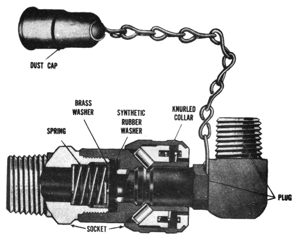
Figure 35.8. (Added.) Cutaway view of socket
and plug. Disassembly is permitted only as directed in paragraph 66.1.
(2) Damaged plug. Repair damaged or nicked end of plug by filing plug
end square and smooth. File off as little as possible. Test for leakage
at socket by installing pressure tank and valve assembly, as in c
above, and then opening pressure-tank valve. If leak persists at joint
between socket and plug, replace plug by unscrewing old plug, screwing
new plug in position, and tightening with wrench. Replace entire plug.
Do not attempt to unscrew the cylindrical portion from the square
portion.
67. PRESSURE REGULATOR.
**
***
e. Maintenance (Added).
(1) Spring type (Hoke) pressure regulator. Except for adjustment to
increase or decrease pressure, do not attempt to maintain or repair the
spring type (Hoke) pressure regulator. If damaged or defective, it must
be replaced by a dome type (Grove) pressure regulator.
(2) Dome type (Grove) pressure regulator (B81-1-778). Replacement
parts for maintaining the dome type (Grove) regulator are available for
use by chemical maintenance companies, as shown in Army Service Forces
Catalog CW 9-440114, List of All Service Parts and Higher Echelon Spare
Parts for Flame Thrower, Portable, M2-2 (25 November 1944).
74. VALVE GRIP.
**
***
c. Installing valve grip.
(1) Place grip safety * * * right valve grip. (Fig. 48.) Do not
accidentally place the lower forward extension of the grip safety
over the lower rear extension of the valve lever. If this overlapping
occurs, the small projection at the bottom of the grip safety may be
broken off. Be sure the * * * of grip safety.
**
***
77. SHIPMENT AND STORAGE.
**
***
c. Class of supply (Added). The portable flame thrower is a class
IV supply item.
78. REFERENCES.
Reference pertaining to * * * flame throwers include:
**
***
TM 9-850 Cleaning, Preserving, Lubricating * * * the
Ordnance Department
TM 3-377, Compressor, Air, Gasoline Engine-driven,
7CFM, M1 (For Charging Flame Throwers
and Cylinders)
TB CW 18, Kit, Fuel Filling, Flame Thrower, E6 (for filling
mechanized and portable flame throwers)*
TB CW 20, Cleaning Interiors of Compressed Gas Cylinders,
Tanks, and Accessories*
TB ENG 39, Safe Handling of Compressed Gases*
ASF Catalog CW 7-440114, Organizational Spare Parts
and Equipment: 1st and 2d Echelons: for
Flame Thrower, Portable, M2-2 (25 November
1944)
ASF Catalog CW 9-440114, List of all Service Parts and
Higher Echelon Spare Parts for Flame
Thrower, Portable, M2-2
ASF Catalog CW 6-445115, Sets of Tools, Equipment, and
Similar Material: Kit, Service, for Portable
Flame Thrower, M2-2
ASF Catalog CW 9-445115, List of all Parts and Higher
Echelon Spare Parts for Kit, Service, for
Portable Flame Thrower, M2-2
FS 3-33, Portable Flame Thrower M2-2, Part 1, Nomenclature
and Operation.
* Technical Bulletins are to be superseded by appropriate
War Department manuals or changes to manuals.
[AG 300.7 (11 Apr 45)]
By order of the Secretary of War:
G. C. MARSHALL
Chief of Staff
Official:
J. A. ULIO
Major General
The Adjutant General
Distribution:
AAF (Cml O) (10); AGF (Cml O) (10); ASF (2); T of Opn
(Cml O) (10); Arm & Sv Bds (1); Def Comd (2); S Div ASF
(1); Tech Sv (2) except CWS (45); SvC (Cml O) (4); PE
(Attn: Cml O) (2); Sub-PE (Cml O) (2); PG (2); Ars 3 (2);
ASF Dep (CW Sec) (2); ASF Dep (2); Dep 3 (2); Pro Dist 3
(2); Tech Sv C (2); USMA (20); Tng C (2); A (2); CHQ
(5); B (1); R (5); Bn 2 (2), 3 (5), 7, 17 (2); C 2 (2), 3 (5),
7, 17 (2); AF (2); W (Cml O) (1); Five (5) copies to each
of the following: T/O & E 5-15; 5-16; 5-17; 5-35; 5-36; 5-37;
5-171; 5-175; 5-176; 5-192; 5-215; 5-216; 5-217; 5-235; 5-236;
5-238; 5-475T; 5-476T; 5-477T.
Refer to FM 21-6 for explanation of distribution formula.
TABLE OF CONTENTS
| PART ONE | |||
| INTRODUCTION | |||
| Paragraph | Page | ||
| SECTION I. | GENERAL | ||
Scope | 1 | 1 | |
Records | 2 | 1 | |
| SECTION II. | DESCRIPTION AND DATA | ||
Uses of flame throwers | 3 | 1 | |
Characteristics and employment | 4 | 4 | |
Description and functioning | 5 | 6 | |
Identification information | 6 | 9 | |
Differences in models | 7 | 9 | |
Interchanging parts with M1 or M1A1 flame thrower | 8 | 9 | |
Data | 9 | 9 | |
| SECTION III. | TOOLS, PARTS, AND ACCESSORIES | ||
Items with each flame thrower | 10 | 11 | |
| PART TWO | |||
| OPERATING INSTRUCTIONS | |||
| SECTION IV. | GENERAL | ||
Scope | 11 | 14 | |
| SECTION V. | SERVICE UPON RECEIPT OF EQUIPMENT | ||
New equipment | 12 | 14 | |
Used equipment | 13 | 15 | |
| SECTION VI. | CONTROLS | ||
Controls | 14 | 15 | |
| SECTION VII. | OPERATION UNDER USUAL CONDITIONS | ||
Training | 15 | 16 | |
Charging, filling, and servicing | 16 | 16 | |
Connecting tank group and gun group | 17 | 16 | |
Loading with ignition cylinder | 18 | 17 | |
Carrying the tank group | 19 | 21 | |
Carrying the gun | 20 | 21 | |
Opening pressure-tank valve | 21 | 22 | |
Ranges | 22 | 22 | |
Wind deflection | 23 | 22 | |
Firing positions | 24 | 23 | |
Aiming | 25 | 23 | |
Firing | 26 | 23 | |
Ceasing or interrupting fire | 27 | 26 | |
Additional bursts | 28 | 26 | |
Soaking the target | 29 | 26 | |
After firing | 30 | 26 | |
| SECTION VIII. | AUXILIARY EQUIPMENT | ||
Ignition cylinder | 31 | 27 | |
Charging pressure tank | 32 | 28 | |
Precautions when pressure-charging | 33 | 32 | |
Characteristics of fuels | 34 | 33 | |
Preparation of thickened fuels | 35 | 34 | |
Preparation of liquid fuels | 36 | 38 | |
Filling by pouring | 37 | 39 | |
Filling by force pump | 38 | 40 | |
Filling by blowing | 39 | 40 | |
Precautions with fuels | 40 | 43 | |
| SECTION IX. | OPERATION UNDER UNUSUAL CONDITIONS | ||
Wet conditions | 41 | 44 | |
Dust and mud | 42 | 44 | |
Heat | 43 | 44 | |
Cold | 44 | 45 | |
Wind | 45 | 45 | |
| SECTION X. | DEMOLITION TO PREVENT ENEMY USE | ||
Destruction procedure | 46 | 45 | |
| PART THREE | |||
| MAINTENANCE INSTRUCTIONS | |||
| SECTION XI. | GENERAL | ||
Scope | 47 | 46 | |
| SECTION XII. | SPECIAL ORGANIZATIONAL TOOLS AND EQUIPMENT | ||
Service kit | 48 | 46 | |
| SECTION XIII. | LUBRICATION | ||
Lubrication | 49 | 49 | |
| SECTION XIV. | PREVENTIVE MAINTENANCE SERVICES | ||
General | 50 | 49 | |
Before-operation service of tank group | 51 | 50 | |
Before-operation service of gun group | 52 | 50 | |
Service when filling and charging | 53 | 52 | |
Service when firing | 54 | 53 | |
Service after firing | 55 | 53 | |
Service after six firing missions | 56 | 54 | |
| SECTION XV. | TROUBLE SHOOTING | ||
Precautions | 57 | 55 | |
Fuel leaks | 58 | 55 | |
Safety head “blows” (breaks) | 59 | 56 | |
Carrier uncomfortable | 60 | 56 | |
Short range | 61 | 56 | |
Fuel-valve failure | 62 | 57 | |
Failure of ignition cylinder to ignite | 63 | 57 | |
Failure of fuel to ignite | 64 | 58 | |
| SECTION XVI. | TANK GROUP | ||
General | 65 | 58 | |
Pressure tank and valve assembly | 66 | 59 | |
Pressure regulator | 67 | 63 | |
Fuel-tank assembly | 68 | 65 | |
Filling and safety-head plug assemblies | 69 | 67 | |
Tank coupling | 70 | 69 | |
Carrier | 71 | 71 | |
| SECTION XVII. | GUN GROUP | ||
General | 72 | 74 | |
Fuel-hose assembly | 73 | 74 | |
Valve grip | 74 | 75 | |
Barrel and valve-body assembly | 75 | 77 | |
Ignition head | 76 | 82 | |
| APPENDIX | |||
| SECTION XVIII. | SHIPMENT AND STORAGE | ||
Shipment and storage | 77 | 86 | |
| SECTION XIX. | LIST OF REFERENCES | ||
References | 78 | 87 | |
| INDEX | |||
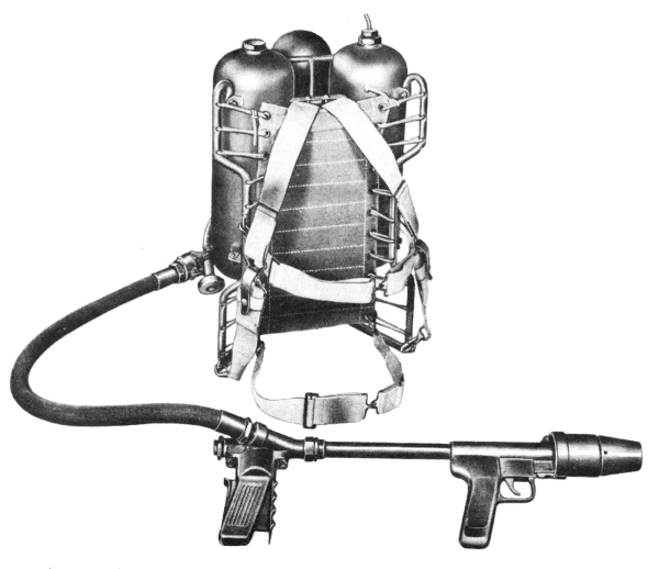
Fig 1. Portable flame thrower M2-2.
PART ONE
INTRODUCTION
Section I GENERAL
1. SCOPE.
a. Arrangement. This manual is published to guide and inform
personnel using and maintaining flame thrower, portable, M2-2. Part One
contains general information; Part Two is a guide to operation;
Part Three gives maintenance procedures. The Appendix discusses
shipment and storage procedures, and applicable publications.
b. References. References are listed in the Appendix. The
list includes field manuals, technical manuals, and Army Regulations.
2. RECORDS.
Although no standard maintenance forms and records are furnished,
an improvised list should be kept of the number of times each flame
thrower has been fired. The list indicates when it is necessary
to provide the after-six-missions preventive maintenance and
lubrication. It should be tacked or glued to the inside surface
of the packing-chest lid and each flame thrower should always be
returned to its own chest.
Section II DESCRIPTION
AND DATA
3. USES OF FLAME THROWERS.
Flame throwers can: a. Penetrate openings, such as embrasures
and gun ports, and fill the fortifications with flame and
smoke.
b. Burn, asphyxiate, and blind enemy personnel, causing casualties,
shock, panic, and abandonment of a fortified position.
c. Ignite combustible parts of shelters and materiel and start
detonation of sensitive ammunition and explosives.
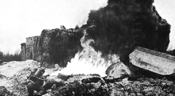
Fig 2. Firing with liquid fuel.
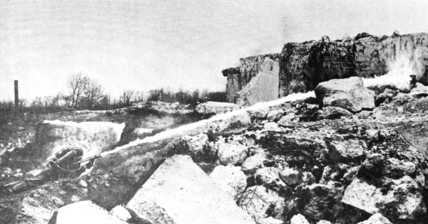
Fig 3. Firing with thickened fuel. Thickened fuel
has longer range than liquid fuel and burns on target for several
minutes.
d. “Shoot around corners,” when fuel is fired from dead or
blind angles. This is made possible by the billowing and swirling
movements of flaming gases. Blazing thickened fuels also
ricochet from wall to wall in fortifications.
e. Cause the enemy to close ports, temporarily putting the emplacement
out of action and thus protecting the demolition party.
f. Mop up dug-in personnel.
g. Eliminate enemy nests in street or jungle fighting.
4. CHARACTERISTICS AND EMPLOYMENT.
a. Action. Fuel is propelled into the target by a charge of
highly compressed air or nitrogen. As fuel leaves the gun of the
M2-2 portable flame thrower (Fig 1), it is ignited by contact with
flame from charges of incendiary mix held in an expendable ignition
cylinder.
b. Bursts. A continuous stream or separate bursts may be
fired for approximately 8 to 9 seconds, not including time between
the bursts. The five incendiary charges in the ignition cylinder
are controlled by the trigger and can ignite several bursts.
c. Range. Portable flame throwers are fired at extremely
close or point-blank range for best results. (Par 22) Effective
range for liquid fuels (Fig 2) is as far as 20 yards, and for thickened
fuels (Fig 3), 40 yards, but underbrush and adverse winds
can reduce the distances.
d. Weight. To keep the weight as light as possible and still
provide strength to withstand very high pressures, most parts
are made of aluminum or sheet steel.
e. Tactics. Two or more flame throwers are generally used
on a mission with other weapons of the assault squad. (See FM
31-50, “Attack on a Fortified Position and Combat in Towns.”)
f. Firers and assistants. One man carries and fires each
flame thrower. Well-armed assistants accompany firers to give
close protection and to serve as emergency replacements.
Whereas the M1A1 portable flame thrower may require the help
of an assistant to open the pressure-tank valve, the M2-2 flame
thrower pressure-tank valve is located within reach of the firer
and is operated by him without assistance. Firers and assistants
should be thoroughly trained in operation of the weapon.
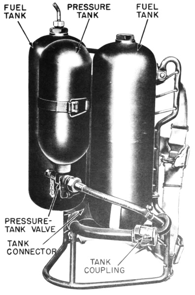
Fig 4. Tank group.
g. Charging and filling. In order to replace pressure tanks
(cylinders) of earlier types of flame throwers, it is necessary
to unscrew and screw threaded connections. Experience has
shown that this frequently resulted in damage to threads, leakage,
loss of pressure, and loss of range. It is also necessary to use
tools to replace each pressure tank (cylinder). The design of the
M2-2 flame thrower eliminates these difficulties. The tank group
(Fig 4) may be charged and filled as a unit with or without gun
and hose. The quick-connecting tank coupling permits rapid
interchanging of empty and full tank groups by the firers or assistants.
6
This is done without tools, takes very little time, and
cannot cause leakage, loss of pressure, and loss of range due to
damaged threads.
5. DESCRIPTION AND FUNCTIONING.
The flame thrower consists of two major groups: tank group and
gun group. Detailed descriptions of assemblies and parts are
included in Paragraphs 66 through 76.
a. Tank group. (Figs 4 and 5) Carried upon the firer’s back,
the tank group holds fuel and pressure. The tank group may be
identified as tank, fuel, portable flame thrower, M2, assembly
D81-1-482. It consists principally of:
(1) Two fuel tanks, holding a total of 4 gallons of fuel, and
joined by a tank connector to form a single fuel reservoir.
(2) Pressure tank, charged with highly compressed air or
nitrogen used to propel fuel from the fuel tanks through the gun
to the target. The tank is large in capacity to assure ample pressure
and uniformly long range throughout the firing.
(3) Pressure-tank valve, which releases air or nitrogen
through the pressure regulator to the fuel tanks. The valve can
be opened by the firer without the assistance required in the case
of the M1A1 flame thrower.
(4) Pressure regulator, which automatically assures delivery
of air or nitrogen to the fuel tanks at the proper pressure. The
regulator is located in a position where it cannot easily be damaged.
(5) Carrier, which supports the tank group on the firer’s back
and shoulders and secures it to his body. It includes body and
shoulder straps and quick-releasing fasteners.
b. Gun group. (Fig 6) Carried, aimed, and operated by the
hands of the firer, the gun group ignites the fuel and directs the
flame into the target. It includes:
(1) Fuel hose, which conveys fuel from the tank group to the
gun. The fuel hose may be requisitioned as hose, fuel, portable
flame thrower, M1, assembly B81-1-498.
(2) Gun, which ignites the fuel and directs it to the target.
The gun may be identified as gun, portable flame thrower,
M2, assembly D81-1-405. It consists of:
(a) Fuel valve, which discharges fuel through the barrel.
The valve is operated by squeezing the valve lever and the grip
safety, which are on opposite sides of the valve grip. The valve
also includes a barrel from which the fuel is ejected. The ignition
head is supported on the front of the barrel.
(b) Ignition head, which ignites the fuel as it passes
from the nozzle of the barrel. With each pull of the trigger on the
front grip, one of five charges of incendiary mix in an ignition
cylinder is ignited. This pilot flame ignites the fuel as it is
propelled from the gun.
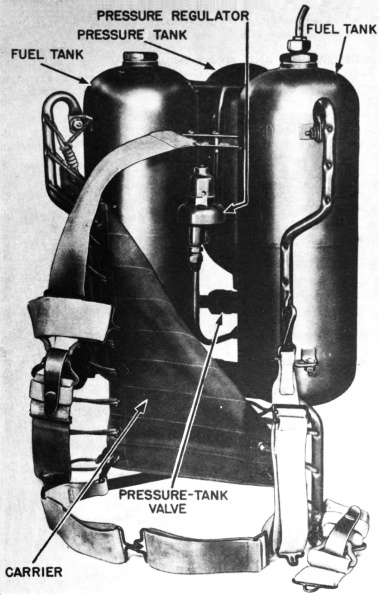
Fig 5. Tank group with carrier folded back to show
construction.
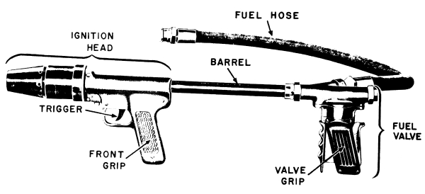
Fig 6. Gun group of portable flame thrower M2-2.
6. IDENTIFICATION INFORMATION.
The words “Chemical Warfare Service,” model numbers, serial
numbers, lot numbers, weight, cubage, manufacturers’ names,
contract number, and date of packing are indicated on the packing
chest or the equipment. The numbers and letters shown on the
equipment should be referred to when repairs are required. The
tank group and the gun (without the fuel hose) may each be marked
“M2” and the fuel hose may be marked “M1,” although all of
these are components of the M2-2 portable flame thrower.
7. DIFFERENCES IN MODELS.
a. M2-2 and E3 portable flame throwers. Portable flame
thrower M2-2 is identical in all important respects with portable
flame thrower E3. (The E3 flame thrower, when standardized
with some modifications, became the M2-2.) Operation and maintenance
of the M2-2 and E3 are in general the same, and the parts
are interchangeable.
b. M2-2, M1, and M1A1 portable flame throwers. Portable
flame thrower M2-2 has the same fuel capacity but differs in
construction from portable flame throwers M1 and M1A1. Parts
are not interchangeable except as stated in Paragraph 8.
8. INTERCHANGING PARTS WITH M1 OR M1A1 FLAME
THROWER.
To use an M2-2 gun with tank group (fuel unit) of an M1 or M1A1
portable flame thrower:
a. Remove fuel hose from M2-2 gun.
b. Screw a 3/4-inch by 1/2-inch pipe bushing into the side
opening of the fuel-valve body. This bushing is furnished in the
spare parts kit of each M2-2 portable flame thrower. (Par 10)
c. Screw the fuel-hose assembly of the M1 or M1A1 flame
thrower into the 1/2-inch opening of the bushing, using a wrench
to make a tight connection.
9. DATA.
All data are approximate.
a. Range. See Paragraph 22.
b. Duration of fire.
(1) Fuel.
(a) Continuous discharge of approximately 8 to 9 seconds,
or
(b) Several short bursts totalling approximately 8 to 9 seconds
(not including time between bursts).
(2) Ignition cylinder. Five charges in each cylinder, 8 to 12
seconds per charge.
c. Weights. | |
|---|---|
| Pounds | |
Portable flame thrower M2-2, empty, in shipping | 110 |
Portable flame thrower M2-2, empty | 43 |
Portable flame thrower M2-2, filled with fuel | 68 to 72 |
Tank group, empty | 35 |
Tank group, filled with fuel | 60 to 64 |
| Gun group | 8 |
d. Dimensions. | |
| Inches | |
Gun, length | 30 |
Fuel hose, length | 37 |
Tank group, height | 27 |
Tank group, width | 20 |
Tank group, breadth | 11 |
Packing chest | 34 x 23 x 19 |
e. Capacity of weapon. | |
Ignition cylinder (M1 or E1) | 1 (which includes 5 incendiary charges) |
Fuel | 4 gallons plus void for air or nitrogen |
f. Pressures. | |
| Pounds per sq. in. | |
Pressure tank | 1,700 to 2,100 |
Fuel tanks | 350 |
g. Ratio of expended supplies. For every 100 complete fillings
of the flame thrower, the following supplies are normally expended:
(1) Nitrogen contained in fifteen 220-cubic-foot cylinders or an
equivalent volume of compressed air. (Eleven cylinders are expended
if the four-place arrangement described in Paragraph 32
is used.)
(2) 450 gallons of fuel (400 gallons plus 50 gallons for spillage,
spoilage, and evaporation).
(3) 100 ignition cylinders.
(4) If thickened fuel is used, 135 pounds (in cans of 5-1/4 pounds
each) of U. S. Army fuel thickener.
Section III TOOLS,
PARTS, AND ACCESSORIES
10. ITEMS WITH EACH FLAME THROWER.
The items listed below or their equivalents (Fig 7) are included
in each M2-2 flame-thrower packing chest, in addition to the
flame thrower. Numbers listed with items are Chemical Warfare
Service stock numbers.
a. Kit, tool, for portable flame thrower M2-2, assembly
B81-6-50.
b. Kit, spare parts, for portable flame thrower M2-2, assembly
B81-6-52.
c. Cylinder, ignition, portable flame thrower M1. (6 cylinders,
in 3 cans containing 2 each)
d. Technical Manual 3-376A, “Portable Flame Thrower
M2-2.”
e. Gun mounting board. (Fig 10)
f. Plug, coupling, E81-1-514 (for use in tank coupling when
filling tank group with gun detached).
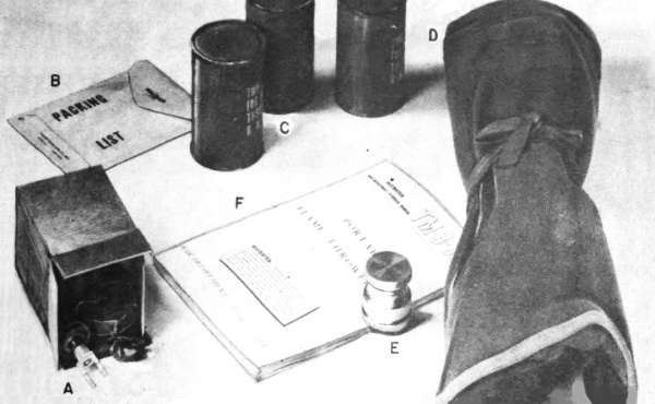
Fig 7. Items packed in chest with each flame thrower: A—Spare
parts kit; B—Packing list; C—Three cans of ignition cylinders;
D—Tool kit; E—Coupling plug; F—TM 3-376A, “Portable
Flame Thrower M2-2.”
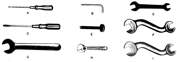
Fig 8. Contents of tool kit:
A. 1 Screw driver, cabinet, 4-1/2-inch blade length, 3/16-inch blade diameter, H22-50-13.
B. 1 Wrench, hex, 1/8-inch across flats for 1/4-inch socket-head set screws, H22-49-12.
C. 1 Wrench, engineers’, double head, 3/4-inch and 7/8-inch openings, 9 inches approx length, H22-49-115.
D. 1 Screw driver, common, 6-inch blade length, 5/16-inch blade diameter, H22-50-6.
E. 1 Wrench, valve-adjusting, assembly, A81-6-48.
F. 1 Wrench, heavy “S”, 1-3/8-inch and 1-1/2-inch openings, 12 inches approx length, H22-49-113.
G. 1 Wrench, engineers’, single head, 1-1/8 inch opening, 10-1/2 inches approx length, H22-49-31.
H. 1 Wrench, adjustable, single end, 6 inches approx length (crescent type), H22-49-67.
I. 1 Wrench, heavy “S”, 1-3/8-inch and 1-3/4-inch openings, 12 inches approx length, A81-6-49.
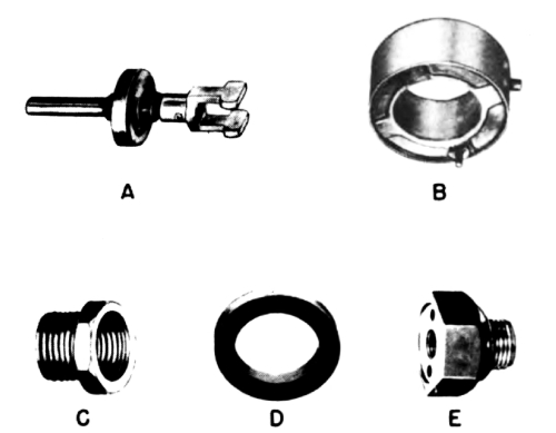
Fig 9. Contents of spare parts kit:
A. 1 Diaphragm, valve, assembly, A81-1-416.
B. 1 Case, spring, assembly, B81-1-444.
C. 1 Bushing, pipe, head, 3/4-inch by 1/2-inch (galvanized iron), H98-5-93.
D. 2 Washers, coupling, A81-1-513.
E. 3 Heads, safety, R81-1-561.
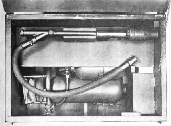
Fig 10. Packing chest open, with gun on mounting board. Tool kit,
spare parts kit, and cans of ignition cylinders in boxes at right.
PART TWO
OPERATING INSTRUCTIONS
Section IV GENERAL
11. SCOPE.
Part Two of this manual is for the guidance of operating personnel.
It includes information on the controls and on operation.
Section V SERVICE UPON
RECEIPT OF EQUIPMENT
12. NEW EQUIPMENT.
Upon receipt of a new flame thrower, the following procedure should be
carried out:
a. Cut packing-chest steel straps and seals with pliers.
b. Remove the screws, if present, from top of chest.
c. Open two latches at front of chest.
d. Lift lid backward and connect chain from inside of chest to inside
of lid.
e. Remove moistureproof paper.
f. Remove gun from carton. After removing waterproofing tape from
ends of hose, connect hose and gun. (Par 17)
g. Remove mounting board and place gun with hose on the board as
shown in Figure 10.
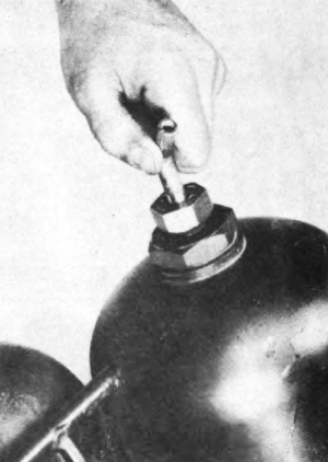
Fig 11. Screwing deflector tube in safety head on left
fuel tank.
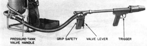
Fig 12. Controls for operation of portable flame thrower
M2-2.
h. Remove spare parts kit, tool kit, cans of ignition cylinders, and
other items from packing chest.
i. Compare contents with packing list found in or on packing chest.
Inspect all contents carefully for completeness, correct adjustment,
and good condition.
j. Insert deflector tube in safety head on left fuel tank. (Fig 11)
Outlet should face to rear and at a 45-degree angle to operator’s left
shoulder. (Fig 18) Screw in deflector tube by hand; do not use wrench
on deflector tube. Tighten lock nut with wrench.
k. Before use on a mission, test-fire the weapon. (Par 56 b)
l. Save the packing chest for storage of the equipment when flame
thrower is not being carried on a firing mission or serviced.
13. USED EQUIPMENT.
When they apply, the same steps should be taken as in Paragraph 12. Any
worn or damaged parts should be replaced. Areas where paint has worn
off should be touched up with fresh paint.
Section VI CONTROLS
14. CONTROLS.
The firer uses the pressure-tank valve handle, the trigger, and
the valve lever and grip safety (Fig 12) in succession as follows:
a. Valve handle. The pressure-tank valve is operated by turning
a handle on the valve flexible shaft within reach of the firer.
Counterclockwise operation of handle releases pressure to the
fuel tanks. Clockwise turning closes the valve.
b. Trigger. The trigger is at the front grip of the gun. Pulling
the trigger vigorously ignites an incendiary charge in the ignition
cylinder. This in turn ignites the fuel as it leaves the gun. The
trigger action also causes the ignition cylinder to revolve one-fifth
of a turn, presenting another charge for firing. Each of the
five charges may thus be used in rapid succession, if necessary,16
by pulling the trigger vigorously as many as five times.
c. Valve lever and grip safety. The valve lever and grip safety
are mounted on opposite sides of the valve grip of the gun. When
both controls are compressed, fuel is propelled from the gun. If
either the valve lever or the grip safety is not compressed, the
fuel valve remains closed and the fuel remains in the weapon.
Section VII OPERATION UNDER
USUAL CONDITIONS
15. TRAINING.
Effective use of the M2-2 portable flame thrower can be achieved
only by diligent practice with the weapon. Untrained firers or
assistants should never be sent on a mission.
a. Practice. Firers should practice under varying conditions
of wind, range, elevation, depression, and traverse. The shortness
of the total firing time (approximately 8 to 9 seconds) demands
split-second judgment and coordination.
b. Use of water in training. Water may be used (instead of
fuel) for elementary practice firing. Ignition cylinders are not
used with water. The water under pressure may cause serious
injuries to personnel at 10 yards. After practice with water, the
gun should be disassembled (Pars 73 through 76), cleaned and
dried piece by piece, and lubricated. (Par 49)
c. Use of fuel in training. When using fuel in training, select
or prepare a practice field of fire which provides at least 125
yards for range and 30 yards for spread. If the field contains
dry grass, brush, or other flammable material, a fire-fighting
squad should be available with equipment and source of water.
Assistants and observers should stay well behind the firer because
of danger from wind shifts. See Paragraph 40 for additional
precautions.
16. CHARGING, FILLING, AND SERVICING.
Before use on missions or for training, flame throwers must be
charged, filled, and serviced. Charging with compressed air or
compressed nitrogen is described in Paragraphs 32 and 33;
filling with fuel in Paragraphs 34 through 40; and servicing in
Paragraphs 50 through 56. Test for pressure. (Par 53 d)
17. CONNECTING TANK GROUP AND GUN GROUP.
If a charged and filled tank group has been brought up to replace
an emptied one:
a. Place the new tank group on the ground with the tank coupling17
on top. If the filling is thickened fuel, allow the tank group
to rest in this position for from 1 to 2 minutes.
b. Remove coupling plug from new tank group and disconnect
gun group from emptied tank group. Place unthreaded end of fuel
hose in tank coupling and lock in place. (Par 70)
c. Lock the coupling plug in the emptied tank group.
18. LOADING WITH IGNITION CYLINDER.
a. General. Just before the start of a mission, load an unused
ignition cylinder into the ignition head. (M1 and E1 ignition
cylinders are identical and may be used interchangeably.) Cylinders
are packed two to a can. Do not open cans until ready
to load for a mission. The second cylinder in the can should be
used in another flame thrower on the same mission or as soon
as possible after opening the can. Partly used cylinders may be
employed in training.
b. Precautions. Care must be taken, whenever cylinders are
handled, to avoid any blows or pressure against the metal match
ends. (Fig 13) Face, hands, and other parts of the body should
never be exposed to front of cylinder or front of gun.
Fig 13. Ignition cylinder before use.
c. Procedure. Loading procedure is as follows:
(1) Unscrew and remove ignition shield. (Fig 14)
(2) Place ignition cylinder on end of barrel (Fig 15), being
careful not to grasp cylinder by its ends.
(3) Raise nozzle end of gun so cylinder slides down against the
spring case of the ignition head. (Fig 16) If necessary, rotate
cylinder so it slips down all the way. Do not force cylinder
into place as forcing may prematurely ignite it.
(4) Rotate spring case and ignition cylinder clockwise as far
as they turn freely.
(5) Place ignition shield over cylinder. Engage the slot in the
shield on the spring-case pin.
(6) Turn shield, screwing it onto ignition-head body. Make
sure the threads engage during the first turn of the shield. When
the slot on the shield engages the latch on the ignition head (Fig 17),
the gun is loaded.
(7) If shield cannot be turned by hand tight enough to engage
latch, unscrew shield. Then turn shield backwards until threads
engage and repeat (6) above.
Fig 14. Unscrewing ignition shield, with pressure on
latch.
Fig 15. Placing ignition cylinder on gun. Care must be
taken to avoid striking or pushing metal matches of cylinder.
Fig 16. Ignition cylinder in place on gun before
replacement of ignition shield.
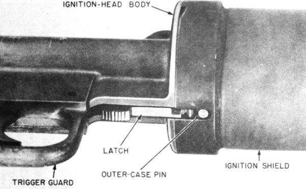
Fig 17. Ignition head assembled for firing of gun.
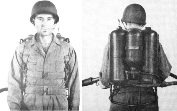
Fig 18. Tank group adjusted on firer.
19. CARRYING THE TANK GROUP.
The tanks are supported on the firer’s back and secured to it by two
shoulder straps and two pairs of body straps. (Fig 18) The straps may
be adjusted by the buckles to fit the operator. The shoulder straps
pass over the shoulders and under the arm pits; the lower body straps
are clasped tightly in front of the body; and the upper body straps are
clasped across the chest to prevent the shoulder straps from slipping
and the tank group from rolling off the back. Adjustments to the
various straps should be made until the unit is carried with the bottom
of the fuel tanks at the small of the operator’s back. The tank group
should fit snugly so that it does not shift if the operator changes
position quickly.
20. CARRYING THE GUN.
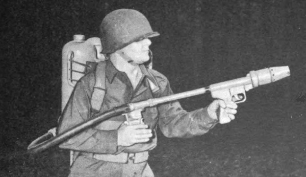
Fig 19. Carrying the gun, with hands in position to fire.
The procedure for carrying the gun is as follows:
a. Carry the gun with the hose at the right side. (Fig 19)
b. Grasp the valve grip with the right hand and the front grip
with the left hand, being careful not to operate the controls until
ready to fire.
c. Keep the gun pointed away from friendly personnel at all
times.
d. Do not face the front of the gun at any time. Even when no
fuel is being ejected, the incendiary charges of the ignition cylinder
can cause severe burns.
e. Keep the gun dry and clean if possible. Avoid getting dirt
or foreign matter into the weapon.
f. Avoid rough handling.
g. Wear gloves if available.
h. Carry any extra ignition cylinders only in metal containers.
21. OPENING PRESSURE-TANK VALVE.
The release of pressure into the fuel tank causes a hissing sound.
Therefore, open the pressure-tank valve while still out of hearing
range of the enemy. Do not, however, open it prematurely because
of the possibility of pressure leaks. To prevent frothing
of the fuel, keep the tank group in as nearly an upright position as
possible when opening pressure-tank valve. Be sure to turn the
valve handle all the way in a counterclockwise direction. Stiffening
of the fuel hose occurs when the pressure-tank valve is opened.
22. RANGES.
Firers and assistants should learn to judge ranges by frequent
practice under varying conditions. The firers should be trained
to approach as close as practicable to the target and to fire if
possible at point-blank range for the greatest results.
a. Point-blank range.
(1) Effects. At very close (point-blank)
range almost all of the burning fuel can be fired at great velocity
directly through ports and openings into the target. Maximum
casualties and damage are caused in the hostile position.
(2) Protection. Common sense precautions are taken to prevent
casualties to friendly personnel from possible ricochet or
rebounding of flame. If the target includes a vertical wall at a
right angle to the firer or other friendly personnel, the weapon
should not be fired at closer than 7 to 10 yards. When the weapon
is fired at small openings in a bunker or pillbox, the firer and
other members of the assault squad should not approach closer
than 7 to 10 yards from the target.
b. Other effective ranges.
(1) Open fields of fire. When
thickened gasoline is used, portable flame throwers may fire
with considerable effect as far as 40 yards under normal conditions,
depending on wind direction and wind speed. Under the
same conditions, liquid fuel maybe effective at 20 yards. Results
and accuracy are not as great as at point-blank range.
(2) Jungle or thick underbrush. If the target is located in
jungle or thick underbrush without cleared fields of fire, the
effective range of the flame thrower is reduced by as much as
one half, depending on the nature and density of the vegetation.
c. Ineffective ranges. Although the flame may reach considerably
farther than the ranges stated in b (1) above it may be
useless because of the steep angle of descent and because much
of the fuel is burned before it reaches the target.
23. WIND DEFLECTION.
Wind is an important factor because of the low velocity of the
flaming fuel. Wind can lengthen, shorten, or deflect the flame.
a. Head winds. Head winds of more than 5 miles per hour tend
to carry heat or even flame back toward the firer. Liquid fuel
should not be fired into a head wind of more than 5 miles per23
hour. The range and accuracy of thickened fuels is reduced.
b. Following winds or very light winds. Best results are obtained
under these conditions.
c. Cross winds. When firing at or near maximum range, cross
winds deflect, breakup, and disperse the flame. They also reduce
the range.
24. FIRING POSITIONS.
a. Ease of aiming. The flame thrower can be fired from any position
that permits sufficient freedom to aim the weapon, subject to the
conditions in b, c, and d, below. This includes standing,
kneeling, and prone. In some instances, flame throwers have been fired
with tank groups resting on the ground or on skids. If used in this
way, the tops of the fuel tanks must be propped up to conform to b,
below.
b. Angles of the tanks. When firing, the bottoms of the fuel
tanks must always be substantially lower than the tops. The tops
of both tanks must also each be the same distance above the horizontal
and neither tank should be tilted to one side. Otherwise,
only a small part of the fuel may be blown from the tanks.
c. Recoil. Stability must be sufficient to withstand the recoil
from the gun. If possible, the firer should hold the gun snugly
against his right side to support it and to absorb its recoil.
d. Protection. Full advantage should be taken of cover and
concealment, such as shell craters and vegetation.
25. AIMING.
a. Sighting. There are no sights on the gun because of the
short range from which it is fired, the variety of fuels used, and
the marked effects of wind. (Par 23)
b. Fortifications. When firing at a fortified position, flame
must be directed into openings (gun ports, firing slits, ventilation
screens, doorways). Flame inside gives the desired effects, but
flame on the outside has little effect on personnel within.
c. Thickened fuel. (Figs 3 and 20) When firing at or near
maximum range, it may take several seconds for a burst of thickened
fuel to carry through the air to the target area. Short bursts
may result in misses at long range for this reason. Skill in aiming
is particularly important with thickened fuel.
d. Liquid fuel. With liquid fuel, the greatest effect may be obtained
by placing the flame directly on the target. (Fig 21)
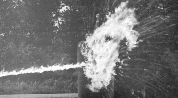
Fig 20. Thickened fuel flame hitting and clinging to target. Fuel burns for several minutes.
Fig 21. Flame (liquid fuel) hitting target.
26. FIRING.
With pressure-tank valve open:
a. Pull trigger. Pull the trigger rapidly and vigorously. A
flash should appear at the front of the gun. This shows that an
incendiary charge of the ignition cylinder has been ignited. Release
the trigger. (If the flash does not appear, pull the trigger
26
again, or as often as necessary up to five times, until a flash appears.)
b. Squeeze fuel valve. Immediately after pulling trigger, compress
the valve lever and grip safety vigorously with the right
hand. Burning fuel will be propelled from the gun.
c. Adjust fire. Direct the flaming fuel at the target. Continue
to squeeze the valve lever and grip safety throughout the burst.
When thickened fuel is fired, follow the fuel with eyes to the side
of the stream in order to observe and correct aim. (If eyes are
directly behind the stream, the flame may obscure the target.)
27. CEASING OR INTERRUPTING FIRE.
To cease or interrupt firing, release the controls.
28. ADDITIONAL BURSTS.
To fire additional bursts, repeat procedure followed in Paragraphs
26 and 27, keeping in mind that there are five incendiary charges
in the ignition cylinder and that the total firing time, not including
time between bursts, is approximately 8 to 9 seconds. Each of
the five incendiary charges in the ignition cylinder burns for
from 8 to 12 seconds.
29. SOAKING THE TARGET.
When liquid fuel is used, it may be desirable to soak the target
with fuel first and ignite it afterward. To do this, fire one or two
short bursts without pulling the trigger. Then follow with an ignited
burst, as in Paragraph 26.
30. AFTER FIRING.
When the firer has returned from his mission, he should:
a. Remove and discard the ignition cylinder, as follows:
(1) Point gun at the ground.
(2) Press latch. (Fig 14)
(3) Unscrew the ignition shield and allow ignition cylinder to
fall out. (Be careful to keep the hands away from the front of the
cylinder.)
(4) Save the partly used cylinder for training use or destroy
it by firing from gun after fuel tanks have been emptied. For information
on care, handling, and storage of cylinders, see Paragraph 31.
b. Close the pressure-tank valve by turning valve handle
clockwise (to conserve remaining pressure in pressure tank).
c. Point the gun away from personnel and blow out the remaining
fuel, if any, from the fuel tanks by squeezing the valve
lever and grip safety until there is no further discharge. The
trigger should not be used during this operation.
d. Take off tank group from the back.
e. Inspect, clean, and maintain the flame thrower (Pars 55 and27
56) or, if experienced maintenance personnel is close at hand, turn
the weapon over to them for servicing.
f. After servicing, place the weapon in the packing chest (Par 77)
for protected storage, or prepare it for the next mission.
(Pars 50 through 53)
Section VIII AUXILIARY
EQUIPMENT
31. IGNITION CYLINDER.
a. Description and functioning. (Figs 13 and 22) Either the
M1 or E1 ignition cylinder may be used. It fits over the fore
part of the barrel assembly and is revolved by the spring case.
(Par 76) The five incendiary charges in the cylinder are spaced
sufficiently far apart in the plastic body to prevent their igniting
one another. Lead-foil seals, plastic closure plates, and waterproof
cement make the unit comparatively waterproof.
Fig 22. Cutaway view of ignition cylinder (M1 or E1).
b. Action. When the trigger rod is pushed forward, one of five
metal matches tipped with red phosphorus scratches an igniting
mixture. The ignition carries to a starter mix and to a few grains
of black powder on top of the incendiary charge. The black powder
blows the foil seal and closure plate clear of the flame thrower,28
and the incendiary charge ignites the fuel as it is discharged from
the nozzle. The incendiary charge burns for from 8 to 12 seconds.
c. Packing. Ignition cylinders are packed two per waterproof
can. Three cans are furnished with each flame thrower. Fifty
cans (100 ignition cylinders) are contained in each packing box of
extra cylinders.
d. Care, handling, and storage. Ignition cylinders contain
hazardous incendiary material and must be handled with due care.
The following precautions should be observed.
(1) Opening cans. Do not open cans containing cylinders until
ready to load for a mission. (Par 18) If an extra cylinder remains
in an opened can, use it as soon as possible. Any defective cylinders,
such as those with damaged closure plates, should be
destroyed. (Pars 30 and 46) Moisture may affect the cylinders
and all possible care should be taken to avoid exposing them to
dampness.
(2) Handling cylinders. Pressure on any of the five metal
matches (Fig 13) may ignite an incendiary charge in the cylinder.
Care must be exercised to avoid putting pressure on the projecting
ends of the matches except when firing the weapon. Ignition
cylinders and cylinder containers should be protected against
shock. Boxes and cans containing cylinders must not be thrown
or dropped.
(3) Storing containers. Containers of ignition cylinders are
best stored in a dry, well-ventilated place, out of the direct rays
of the sun, well protected against excessive temperatures. Smoking
is not permitted and matches are not used where ignition cylinders
are stored.
32. CHARGING PRESSURE TANK.
a. General. The pressure tank of the flame thrower must be
fully charged with compressed air or compressed nitrogen before
the start of a mission. For the M2-2 flame thrower, a pressure
of at least 1,700 pounds per square inch is required. This may be
provided either by the use of an air compressor capable of producing
a pressure of at least 1,700 pounds per square inch, or
by the use of commercial cylinders. The filling and charging
lines from the service kit are used in conjunction with the cylinders.
Before and after charging, follow the procedures described
in Paragraphs 51 and 55.
b. Charging from air compressor. Compressor, air, gasoline
engine driven, 7CFM, M1, is a self-contained, skid-mounted
machine designed for use with flame throwers. It is capable of
charging pressure tanks of flame throwers and large 200- or
220-cubic-foot commercial cylinders as well. Instructions for
use of the compressor will be found in the manual accompanying it.
c. Charging from cylinders. If an air compressor is not available,29
it is necessary to use cylinders containing nitrogen or air.
(1) Volume and pressure. Cylinders come charged with 200
to 220 cubic feet of air or nitrogen. Since cylinders with 220
cubic feet of air or nitrogen have a higher initial pressure,
it is recommended that they be procured, if obtainable. All cylinders
used must have a pressure of at least 600 pounds per
square inch. One or more of the cylinders must have a pressure
of at least 1,800 pounds per square inch. Two or more cylinders,
preferably at least four, should be used, if available.
(2) Charging capacity. Fully charged cylinders, if properly
used in rotation, have capacity for charging pressure tanks
approximately as follows:
| 1 cylinder (used alone) | 2 | pressure tanks |
| 2 cylinders (in combination) | 6 | pressure tanks |
| 4 cylinders (in combination) | 24 | pressure tanks |
| 5 cylinders (in combination) | 36 | pressure tanks |
| 6 cylinders (in combination) | 48 | pressure tanks |
(3) Apparatus. The apparatus for charging two pressure tanks
by the use of cylinders consists of a filling line, two charging
lines, and two cylinders. (Fig 23) The filling line and charging
lines are obtained from the service kit. (Par 48) Plugs are provided
to close off either half of the filling line when only one
flame-thrower tank group is to be charged.
(4) Warning. Oxygen is sometimes shipped in cylinders having
the same threads as nitrogen cylinders. If oxygen not mixed
with nitrogen, as in air, is introduced into the fuel tanks of the
portable flame thrower, a violent explosion may result. Therefore,
the greatest care must be exercised to see that only air or
nitrogen is used. Before a cylinder is connected, it should be
tested to determine that it does not contain straight oxygen or
some combustible gas. This may be done by introducing a burning
splint into a jet of the contents. Oxygen causes the splint
to burn quickly, whereas nitrogen extinguishes the flame. To
make the test:
(a) Fasten a thin splint of wood to a wire at least a foot long.
(b) Ignite the splint.
(c) Stand aside and hold it before the cylinder outlet.
(d) Crack the valve slightly to permit a small stream of gas
to emerge.
(e) If the flame flares up, the gas is oxygen and MUST NOT
be used.
(f) If the gas itself catches fire, it may be hydrogen, acetylene,
or some other combustible gas, which also must not be used.
(5) Attaching lines to cylinders. (Fig 23) The procedure for
charging two flame thrower pressure tanks from two cylinders
of nitrogen or compressed air begins as follows:
(a) Remove the valve-protection caps from the cylinders.
Fig 23. Charging two pressure tanks, using charging and filling
lines, and cylinders of compressed air or nitrogen.
(b) Place the cylinders side by side with both outlets facing
in the same direction. (If the ground is not level enough for the
cylinders to stand up side by side, lay them horizontally with
both outlets face up.)
(c) Before attaching the filling line to the cylinders, blow
out dust. (Par 33) Then connect, using wrenches to make the
joints pressure tight. Do not kink or bend the flexible hose. Cylinders
must be close enough together to prevent strain on the
flexible hose.
(d) Attach a charging line to each of the two couplings on
the filling line.
(6) Attaching charging lines to pressure tanks.
(a) Close pressure-tank valves.
(b) Unscrew caps from check valves.
(c) Screw the charging-line fittings onto the check valves.
(d) Close bleeders.
(7) Charging. The operation of charging two pressure tanks
from two cylinders is as follows:
(a) Close both filling-line valves.
(b) Open cylinder valves.
(c) Determine which cylinder has the lower pressure by the
gages. Open the filling-line valve at the gage showing the lower
pressure and fill the pressure tanks to the pressure shown by the
gage. Close the valve. Then open the other filling-line valve
and fill the pressure tanks until they reach pressures of at least
1,700 pounds per square inch as shown by the gage.
(d) When the pressure tanks have been filled, close the filling-line
valves. Open the bleeders on the charging lines and leave
them open until the pressure in the charging lines is released.
Then close bleeders. Remove the charging-line fittings from
the check valves. Screw the threaded caps on the check valves
and tighten caps with a wrench.
(e) Repeat steps in (a) through (d) above for as many pairs
of empty flame-thrower tanks as require charging.
(8) To insure proper pressure. Care should be taken to make
certain that the compression delivered to the flame-thrower pressure
tank is a full 1,700 pounds per square inch.
(a) If a filling-line valve leaks, tighten the packing nut on
the valve with a wrench.
(b) When the higher pressure shown on the filling-line gages
is less than 1,700 pounds per square inch, close the filling-line
valve and the cylinder valve on the cylinder having the lower
pressure. Remove and replace this cylinder with a fully charged
cylinder. With chalk, mark the pressure on the cylinder which
has been withdrawn.
(9) After charging. When charging has been completed:
(a) Close the filling-line valves. Observe the pressure indicated
on each gage and mark the pressure on each cylinder using32
crayon, chalk, or pencil.
(b) Close the valves on the cylinders.
(c) Remove the charging-line fittings from the check
valves, replace the threaded caps on the check valves, and tighten
caps with a wrench.
(d) Remove the filling lines from the cylinders. Use two
wrenches and take care not to twist or kink the flexible hose.
Support the lines during the operation so that their full weight
does not hang on the flexible hose during removal.
Fig 24. Arrangement of cylinders and lines for charging four
flame throwers. Flexible hose (assembly E81-3-6) from
service kit is used to connect two filling lines.
(10) Use of four-place lines. (Fig 24) The filling and charging
lines found in two or more service kits may be combined for more
efficient charging of large numbers of pressure tanks. An additional
flexible hose is provided in each service kit for connecting
two filling lines. The procedure for charging is similar to that
described above for the two-place line. Air or nitrogen is taken
first from the cylinder with the lowest pressure and last from the
cylinder with the highest pressure. See a (2) above.
33. PRECAUTIONS WHEN PRESSURE-CHARGING.
Personnel will familiarize themselves with the following precautions:
a. Handling. Handle all cylinders and flame throwers carefully;
never drop them and never subject them to shocks or blows.
Keep valve-protection caps secured when cylinders are being
handled, except when such handling is incident to the use of the
nitrogen or air.
b. Storage. Keep all cylinders and charged flame throwers or
tank groups (Par 77) in open or closed storage. They must, however,
be protected from dampness and excessive rise in temperature
caused by the direct rays of the sun or other source of heat.
Avoid storing them near highly flammable substances, or in places
where they may be struck by moving objects. Segregate empty
cylinders to avoid confusion.
c. Personnel. Do not attempt to use compressed gases unless
trained in this work. Use gases only for the purposes for which
they are intended.
d. Cylinder valves. Do not tamper with safety devices in cylinder
valves. If available, use the proper replacement parts
for safety devices which are in need of repair. If such parts are
not available, do not attempt to use makeshifts or nonstandard
parts.
e. Opening of valves. Open valves slowly and fully each time
nitrogen or compressed air is transferred from a cylinder. When a
wrench is used, be sure it is one that fits properly, and that it is
kept ready for instant use while the compressed gas is being released.
f. Threads. See that threads match before making connections.
Some valves are provided with special threads which must be
matched by the threads in the equipment being connected.
g. Correct equipment. Use gages, regulators, hose, pipe, and
tubing of the type manufactured or specified for the particular
apparatus or compressed gas.
h. Repair. Never attempt to alter or repair a cylinder.
i. Flames and sparks. Do not permit flames, sparks, or ignition
from the flame thrower or other source to touch hose.
j. Blowing out dust. Immediately before coupling an attachment to the
pressure tank or cylinder valve, open it for an instant to blow out any
dust or dirt. Never stand where gas or dirt may be blown into the eyes
or face. If the valve is difficult to open, apply more force gradually.
k. Special devices. Do not attempt to use any special connections or
equipment without the approval of a qualified expert.
l. Keeping valves closed. Keep the valve of each cylinder closed when
its contents are not actually being released from or admitted to the
cylinder. This applies alike to all cylinders, whether they contain a
compressed gas or are empty.
34. CHARACTERISTICS OF FUELS.
Thickened fuels give up to twice the range of liquid fuels. The
stream of thickened fuel is comparatively narrow. Most of the
glue-like fuel clings to and burns in or on the target for as long
as 6 minutes. Liquid fuels, on the other hand, are largely consumed
in flight to the target. If the location of small openings
in the target is known, the stream of thickened fuel can be spotted34
by accurate aiming so that most of the fuel enters directly
into the openings. While it does not billow around corners as
does liquid fuel, thickened fuel strikes the target with force enough
to ricochet inside. It clings to skin and clothing while burning.
It also has excellent incendiary effects. The initial flame and
smoke are less from thickened fuel than from liquid fuel, but the
lower visibility, greater range, and much longer burning period
of thickened fuel compensate for its smaller screening effect.
Liquid fuels are easier to pour when filling than are thickened
fuels.
35. PREPARATION OF THICKENED FUELS.
a. Ingredients. Thickened fuels consist of U.S. Army fuel
thickener mixed with fuel.
(1) Thickener. U.S. Army thickener is supplied in airtight
cans, each containing 5-1/4 pounds of the material.
(2) Gasoline and fuel oil. Gasoline alone is often used with
thickener, but mixtures of gasoline and light fuel oil may be used
satisfactorily. The light fuel oil can be either No. 1 fuel oil, No.
2 fuel oil, automotive diesel oil, or kerosene. These mixtures
give more heat and do not form crusts. Except in hot climates,
75 percent or more of the mixture by weight or volume should
be gasoline. (If too much light fuel oil is included, the fuel tends
to separate into two layers.) In tropical theaters, a thickened
blend of 50 percent gasoline and 50 percent light fuel oil has been
reported to give favorable results. Storage qualities are not
known, however. Another mixture which has been well recommended
in field reports is 15 gallons of gasoline to 5 gallons of
diesel fuel oil. Issue gasoline may be used, but locally procured
gasolines which contain alcohol are not suitable.
b. Proportion of thickener to fuel. Less thickener is recommended
than formerly. A low ratio of thickener gives a thickened
fuel with many of the characteristics of liquid fuel. One
can of thickener to 20 U.S. gallons of gasoline, or gasoline and
light fuel-oil mixture, gives good results. This is a 4.2 percent
by weight mixture. Except in hot weather, a fuel mixture of less
than 3 percent thickener requires such long stirring that its preparation
is impractical.
c. Equipment. An open-head 55-gallon or 42-gallon drum and
an improvised wooden mixing paddle are used. Five-gallon cans
may be employed to transfer the ingredients. The paddle should
be approximately 5 feet long, 2 inches wide, and 1 inch thick.
If a standard 55-gallon, open-head drum with an internal diameter
of 27-7/16 inches is used, the improvised paddle should be marked
to indicate gallons as follows:
| Gallons | Inches |
|---|---|
| 40 | 23-1/2 |
| 20 | 11-3/4 |
35
Do not use a metal paddle because of the danger of striking a
spark from the drum. Never use galvanized containers for mixing
and storing thickened fuels. These may cause the fuel to break
down and become excessively thin. An improvised funnel may be
helpful in filling drums with prepared fuel for aging or transporting.
d. Temperatures.
(1) Below 50 degrees. If the temperature is
below 50 degrees Fahrenheit, it is helpful to prepare thickened
fuel indoors, in a heated room. All precautions should be particularly
observed. (Par 40)
(2) Above 90 degrees. When the fuel is hotter than 90 degrees
Fahrenheit, the thickener reacts very rapidly. In this case, it is
easier to prepare batches of 20 gallons each, but any number of
batches may be prepared in succession.
e. Moisture.
(1) Effect of moisture. Water in thickened fuel
breaks down or reduces the viscosity of the gel and thereby reduces
the range of the flame thrower. This effect may not be
noticeable at once, but the stability of the fuel is affected.
(2) Dryness of thickener. Dry thickener is extremely hygroscopic,
that is, it absorbs moisture from the atmosphere very
rapidly. For this reason, thickener is shipped in hermetically
sealed tin cans containing the exact quantity of powder required
for mixing with 20 gallons of fuel to prepare a 4.2 percent mixture.
It is important that the gasoline or fuel oil and gasoline
be measured out before the thickener container is opened. The
powder then should be poured immediately into the liquid.
(3) Dryness of containers. It is important that all containers
used in mixing and handling the fuel be dry.
(4) Keeping water out of gasoline. Gasoline, especially when
it has been stored in vented containers, frequently includes free
water. Therefore, when using gasoline from a bulk-storage tank
or an open drum, first place it in a clean, dry drum; allow it to
stand quietly for at least an hour; then carefully pour off the
gasoline from the top and discard the last gallon or two.
f. Pouring and stirring. (Fig 25) The liquid fuel is poured
into the open drum; a pail or a paddle (Par 35 c) is used for measuring.
One man then stirs the fuel vigorously. Another takes a
can of thickener, splits it with a machete, bayonet, or ax, and
pours it immediately into the fuel. Any large lumps of powder
are broken by hand before the powder is added to the fuel. When
mixing 40 gallons at a time, the two cans of thickener should be
opened and added to the fuel in rapid succession. If the contents
of the first can are permitted to gel before adding the second can,
it will be difficult to obtain a uniform mix. Continue to stir.
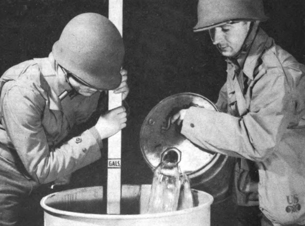
Fig 25. Measuring fuel ingredient into mixing drum. Paddle
for measuring and stirring is improvised.
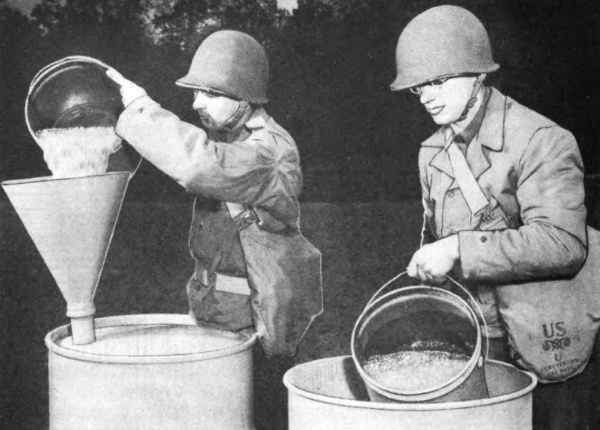
Fig 26. Transferring newly mixed thickened fuel from mixing
drum to storage or shipping container for aging.
g. Examining fuel. Lift the paddle quickly. If the mixture
drops or runs from the paddle, additional stirring is necessary.
When the paddle comes out clean, except for an adhering film,
stirring should be stopped, provided there is no further visible
37
settling of particles of thickener.
h. Loading shipping drums. When stirring is completed, the
mix is immediately bucketed (Fig 26) through a funnel into the
shipping drum. The second bung hole should be open, if possible,
to provide a vent to aid in pouring. Two men do the bucketing,
each handling one pail so that the funnel may be kept loaded with
mix and the shipping drum filled as rapidly as possible. Finally,
the open-end drum should be picked up and its contents poured
into the funnel. Not more than 50 gallons of thickened fuel should
be loaded into a 55-gallon drum. The funnel should then be removed
and replaced by a plug. The vent opening of the drum should
also be closed. (See Paragraph 39 for pressure method of filling
storage drums.)
i. Unused thickener. Any thickener remaining in opened cans
should be discarded. Since moisture in the air can quickly ruin
its properties, no attempt should be made to save it.
j. Aging and storing. Newly mixed fuel has the appearance of
tapioca pudding. (Fig 27) It should preferably be stored overnight
before use. It may, however, be fired within 1 hour after mixing.
To keep fuel in good condition, drums for shipping and storing
must be clean, moistureproof, dry, strong, and unrusted, but not
galvanized. They must be kept tightly closed and should be laid
on their sides so that rain water will not collect around the bungs.
k. Testing fuel. Before use on missions, all fuels should be
tested by being fired from a flame thrower. This is advisable
because the characteristics of the fuel ingredients often vary.
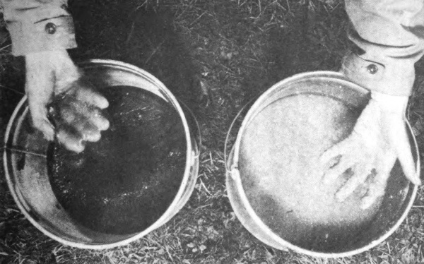
Fig 27. Contrasting newly mixed thickened fuel (right)
with aged fuel (left).
36. PREPARATION OF LIQUID FUELS.
a. Choice of ingredients. Thin fuels are easy to ignite, but
they lack range and are largely burned in flight before reaching
the target. For this reason, liquid fuels should contain the lowest
proportion of gasoline and the highest proportion of heavier oils
that permits easy ignition. In hot climates, less gasoline is
needed than in cold climates. Exactness of proportion, however,
is not of great importance. Suitable blends are as follows:
(1) Equal parts by weight or by volume of gasoline, light fuel
oil, and heavy (bunker) fuel oil. The light fuel oil can be either
No. 1 fuel oil, No. 2 fuel oil, automotive diesel oil, or kerosene.
(2) One part gasoline to four parts of cleaned crankcase drainings.
(Par 36e) Unused motor lubricating oil can be employed in
place of crankcase drainings, but usually it will be unavailable
for flame-thrower use.
b. Preparation of ingredients. Before mixing blends, the following
steps should be taken:
(1) Gasoline, diesel oils, and fuel oils. These fuel materials
should be allowed to stand quietly for at least 30 minutes to permit
any small quantity of water present to settle to the bottom.
When transferring the fuel to another container, remove the fuel
carefully so that no water is remixed with it.
(2) Crankcase drainings. If possible, crankcase drainings
should be allowed to stand quietly in a container for at least 1 day.
When pouring, take care to prevent the transfer of any of the
sludge which may have settled in the bottom of the container.
c. Equipment. An open-head 55-gallon or 42-gallon drum and
an improvised wooden mixing paddle are used. The paddle should
be approximately 5 feet long, 2 inches wide, and 1 inch thick. A
metal paddle should not be provided because of the danger of striking
a spark from the drum. Five-gallon cans may also be furnished
for measuring and transferring ingredients. Clean, unrusted,
steel storage drums should be at hand. They should be at
least 16-gage to have sufficient strength to withstand the internal
vapor pressure of the fuel.
d. Stirring. All the ingredients should be stirred in the drum
with the paddle until they appear to form a uniform mixture.
This should require approximately 2 minutes.
e. Crankcase-draining blends. If crankcase drainings are
used as an ingredient (Par 36b), it is preferable to allow the prepared
mixture to settle for 24 hours after stirring, because the
gasoline in the mixture may cause additional sludge to be deposited.
Even after this settling period, it is recommended that the
mixture be poured through cheesecloth or some similar fabric
before the flame thrower is filled. Crankcase-draining blends
should be allowed to stay in the flame thrower only long enough
for completion of a mission, because additional sludge which may
form from standing will clog the weapon.
f. Transferring. The mixture should be transferred either
directly into the flame-thrower fuel tanks (Pars 37 through 40)
or into storage drums. (Par 35h)
g. Emergency mixing in fuel tanks. In an emergency, mixing
can be done in the flame-thrower fuel tanks by adding the ingredients
in correct proportions and then shaking or stirring.
h. Testing fuel. Before fuel is used on a mission, it should
be tested, if possible, by being fired from a flame thrower.
i. Storage. Fuels may be used immediately after preparation.
If the blend contains crankcase oils, the fuel should be fired as
soon as practicable after filling. Other liquid blends may be
stored indefinitely until required for use. For storage precautions
see Paragraph 40. The storage drums also should be kept
tightly closed to prevent loss of gasoline through evaporation and
to prevent moisture from entering the fuel. If stored in the open,
the drums should be laid on their sides so that rain water will not
collect adjacent to the bungs. An unrusted and undamaged 16-gage
or 18-gage drum has sufficient strength to withstand the
internal vapor pressure of the fuel.
37. FILLING BY POURING.
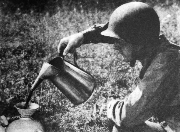
Fig 28. Filling fuel tanks by pouring. Any clean
container may be used. A funnel may be improvised.
(Fig 28) This method is the simplest and quickest for liquid fuel,40
but it may be too slow for some thickened fuels. The procedure is as
follows:
a. Stand the tank group on the ground or a platform. If the tank
group is not connected to the gun group, lock coupling plug in tank
coupling. (Par 70)
b. Using a 1-3/4-inch wrench, unscrew the filling plug and the
safety-head plug.
c. Inspect interior of tanks to see if clean and free from foreign
matter. If not clean, flush with gasoline.
d. Using an improvised funnel, fill to within 2 inches of the top of
both plug openings. This allows sufficient void. The tanks will then
contain approximately 4 gallons of fuel.
e. Wipe the fuel-tank plug seats and the plug threads with a clean,
dry cloth. (Fig 29) If plug has a tendency to freeze to seat, lubricate
(Par 49 b) before screwing in the filling and safety-head plug
assemblies. Tighten with wrench.
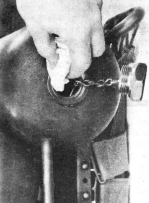
Fig 29. Wiping plug seat.
f. Wipe any spilled fuel from weapon.
38. FILLING BY FORCE PUMP.
A force pump, if available, may be installed with a short length of
pipe in the top opening of a drum of fuel for filling flame-thrower
fuel tanks. Keep working parts of pump clean.
39. FILLING BY BLOWING.
Thickened fuel may be readily forced into the fuel tanks of flame
throwers by the use of extremely low pressures of compressed
air or nitrogen. Flame thrower fuel filling kit E6 or equivalent
may be used. When equipment is available, filling by blowing is
more efficient for filling large numbers of flame throwers with
thickened fuel. Pouring or pumping are more time-consuming,
depending on the consistency of the gel. The consistency may vary
among batches even when the same proportion of thickener is
used. The amount of moisture in the fuel seems to cause this
variation. The precautions listed in Paragraph 40 should be
observed.
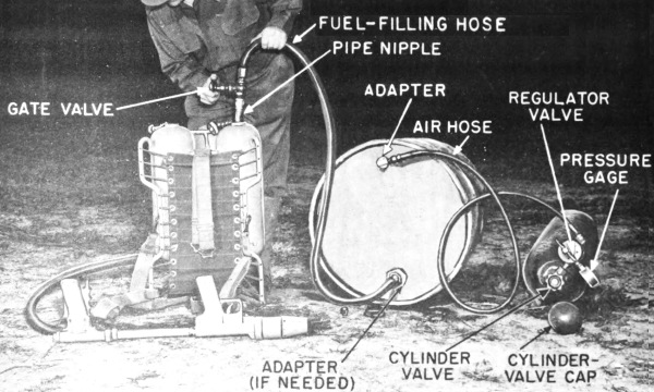
Fig 30. Blowing thickened fuel into fuel tanks by use of
cylinders of compressed air or nitrogen.
a. Source of pressure. When the pressure in cylinders of compressed
air or nitrogen has fallen too low to be of further use in filling
pressure tanks of flame throwers, the remaining pressure42 may be used
to blow fuel into fuel tanks if the regulator valve can reduce pressure
down to 20 pounds per square inch. For precautions, see Paragraph 33.
An air compressor or a hand air pump (tire pump) may be used in place
of a cylinder if the latter is not available. Pressure of no more than
15 to 20 pounds per square inch should be used on the fuel drums. Only
a diaphragm-type regulator valve can be used safely. This valve must be
capable of regulating any pressure that may be applied to it.
b. Drums. Clean, noncorroded, steel, 55-gallon drums should be used.
Drums of United States manufacture which meet requirements will be
stamped ICC-5 or ICC-5A, followed by three numbers in sequence, for
example, “14-55-44.” The number “14” indicates the gage of the metal;
“55” indicates the capacity in gallons; and “44” indicates the year
of manufacture. A steel drum of 14 gage, or heavier, is preferable,
but lighter drums (of 16 or 18 gage) may be used. Drums made of gages
lighter than 18 gage (20-or 22-gage) must not be used. Drums should
never be moved while under pressure.
c. Connections. The source of pressure (see a above), the drum
of fuel, the fuel-filling line, the air hose, and other parts, are
connected as shown in Figure 30. Threaded adapters are used, as
necessary, to fit lines to the drum. All threaded connections should
be made tight by the use of wrenches on the joints. The drum and the
pressure cylinder (if the latter is used) should be laid on their sides
on the ground or a platform. The opening of the drum connected to the
fuel-filling hose should be close to the ground or platform. If tank
group is filled without gun group, lock coupling plug (Par 70) in tank
coupling.
d. Procedure. To fill fuel tanks:
(1) Remove both the filling and safety-head plugs.
(2) Inspect interior of tanks to see if clean and free from foreign
matter. If not clean, flush with gasoline.
(3) Place end of fuel-filling hose in either one of the two fuel-tank
plug holes, using a nipple as a spout.
(4) Start air compressor or pump, or open the valve on the cylinder of
compressed air or nitrogen. Open regulator valve on filling line by
turning handle slowly until gage shows 15 to 20 pounds pressure, but
no more. Caution: “Cracking,” or opening a cylinder valve without
using the proper regulator valve (Par 39 a), may result in explosive
pressure in the drums.
(5) Both tanks must be filled to within 2 inches of their tops. Close
valve on fuel-filling hose to halt flow at this level.
(6) If no additional flame throwers are to be filled, close
pressure-cylinder valve, or stop compressor or pump. Then, using
wrench, slightly loosen the air line at the drum, allowing pressure
to bleed. When the pressure in the drum has fallen to that of the
atmosphere, close regulator valve.
(7) Roll drum slightly and gently until fuel-filling hose is at top of
drum.
(8) If there are valves on each end of the fuel-filling hose, use
wrench to slightly loosen hose, allowing gradual escape of pressure.
Stand away from, and at the side of, the connection. Keep hose pointed
away from other personnel. When all pressure has been released,
complete unscrewing of hose.
(9) Wipe fuel-tank plug seats and the plug threads with a clean, dry
cloth. Then screw in filling plug and safety-head plug assemblies,
applying grease (Par 49 b) if plug tends to freeze to seat. Tighten
with wrench. Wipe any spilled fuel from weapon.
40. PRECAUTIONS WITH FUELS.
a. Flammability. All fuels used in flame throwers obviously are
highly flammable and must be handled, stored, and used with extreme
care. Diesel oil, fuel oil, and kerosene require the same care as does
gasoline.
b. Indoor storage. When it becomes necessary to handle gasoline in
a room or building, the windows and doors should be open and care
taken that no unprotected flame which might ignite the fumes is in the
vicinity. The doors and windows should remain open for a sufficient
length of time afterward to allow any vaporized gasoline to escape.
c. Flames and sparks. The presence of open flames, heated stoves,
electrical tools and apparatus, and other equipment likely to cause
sparks must not be permitted. Even nails and metal cleats in shoes are
a potential hazard in the presence of combustible fumes.
d. Smoking. “No Smoking” signs must be posted in prominent places
about the premises and the rule against smoking must be strictly
enforced.
e. Ventilation and cleaning. The buildings in which fuel is stored
or used must be well ventilated and thoroughly cleaned every day. No
rubbish or other flammable material should be permitted to remain in or
near such buildings.
f. Spillage. Care should be taken that fuel is not spilled. Any
spillage should be removed promptly.
g. Safety cans. Safety cans should be used, if possible, for storing
small quantities of gasoline, as they have covers that must be forcibly
held open to remove or add gasoline.
h. Rags. Metal receptacles with metal lids should be provided for
discarded, oily, or gasoline-soaked rags. These rags must be disposed
of daily.
i. Electrical apparatus. Vaporproof incandescent electric lamps,
switches, and other appliances of approved type should be used. Open
switches, relays, and similar apparatus, or motors with commutators,
must not be used where gasoline fumes may be encountered.
j. Hose. Flexible metal, rubber, and rubber-metal hose should be
inspected regularly (at least four times a year) and discarded when
noticeably deteriorated.
k. Toxic fumes. Gasoline fumes are somewhat toxic and should not be
inhaled.
l. Leaks. Leaks must never be neglected, and the fact that gasoline
is a dangerous liquid must always be kept in mind. Inspections for
leaks should be made frequently, particularly at pipe and hose joints.
m. Fire extinguishers. Carbon tetrachloride, carbon dioxide, or
foam-type fire extinguishers should be provided and located where they
will be accessible in the event of fire. Sand, not water, should be
thrown on burning fuel if suitable extinguishers are not available.
n. Leaded gasoline. Gasoline often contains a poisonous lead
compound. Such gasoline, or fuel containing leaded gasoline, should not
be allowed to touch the body, especially the lips, eyes, open cuts, and
sores.
Section IX OPERATION
UNDER UNUSUAL CONDITIONS
41. WET CONDITIONS.
The M2-2 flame thrower may be carried and fired successfully
in the rain or even after short immersion in water. After use
when wet, it should be dried to prevent rusting, cleaned, and
lubricated. (Pars 49 and 55) Areas where paint has worn off
should be touched up with fresh paint. The weapon should be
stored in a dry place. Moisture must not be allowed to enter
fuel, ingredients of fuel, or containers of ignition cylinders.
42. DUST AND MUD.
Keep all possible dust, earth, and mud out of the flame thrower;
particles may interfere with the operation of spring case, valves,
bearings, and pressure regulator. Store weapons and auxiliary equipment
in closed chests and boxes when not in use. (Par 77) Clean before use.
(Pars 51 and 52)
43. HEAT.
A hot climate or exposure to the sun makes the fuel thinner when in
containers. Thin fuel has shorter range; it is largely consumed in the
air before it reaches usual effective ranges. Where the climate is
torrid, less gasoline or other thinning agents should be used in a fuel
blend than normally. (Pars 34 through 36)
44. COLD.
Cold weather reduces total heat produced at target but seldom enough
to seriously lower value of a firing mission. Incendiary effects may
be decreased because materiel is less flammable when cold. The weapon
may be used at temperatures as low as minus 20 degrees Fahrenheit. To
improve ignition, use more gasoline in fuel than normally. (Pars 34
through 36)
45. WIND.
Flame throwers should not be fired into strong head winds or across
strong side winds. (Par 23)
Section X DEMOLITION
TO PREVENT ENEMY USE
46. DESTRUCTION PROCEDURE.
If circumstances should force abandonment of chemical warfare materiel
in the field, it is destroyed or rendered useless to prevent its use or
study by the enemy. The following methods are recommended:
a. Flame thrower. One or more small-arms bullets through the fuel
tanks will prevent any immediate use of the flame thrower. Additional
rounds may be put through the pressure tank. If the pressure tank is
charged, the pressure-tank valve should be opened for a few seconds,
thus permitting the contents to dissipate. This is necessary if rounds
are to be fired point-blank. The gun may be rendered useless by bending
it over a hard object. A sledge or ax will demolish valves and tubes. A
fragmentation grenade will also achieve demolition.
b. Filling and charging apparatus. The flexible tubing, gages, and
valves may be destroyed by blows with an ax, sledge, or other heavy
instrument. The large pressure cylinders are rendered useless by
releasing the contents and then destroying the valves by blows with an
ax or sledge. Cylinders can be stacked like cordwood in groups of five
and demolished by the detonation of four 1/2-pound blocks (2 pounds) of
TNT in their midst. The air compressor may be destroyed by a similar
procedure.
c. Fuel. Burn.
d. Mixing apparatus. Containers and filling lines may be rendered
useless by ax or sledge blows, or by small-arms fire.
e. Thickener. Cans of thickener should be broken open. Contents
should be thrown into a fire or into a body of water.
f. Ignition cylinders. Burn to destroy. Personnel should stay
several yards from the fire because the cylinders ignite with a slight
detonation.
PART THREE
MAINTENANCE INSTRUCTIONS
Section XI GENERAL
47. SCOPE.
Part Three contains information for the guidance of the personnel of
the using organizations responsible for the maintenance (1st and 2nd
echelon) of this equipment. It contains information needed for the
performance of the scheduled lubrication and preventive maintenance
services as well as descriptions of the major systems and units and
their functions in relation to other components of the equipment.
Section XII SPECIAL ORGANIZATIONAL
TOOLS AND EQUIPMENT
48. SERVICE KIT.
One service kit for portable flame thrower M2-2 will be furnished
for each six M2-2 portable flame throwers. The kit includes tools,
equipment, and spare parts for second echelon maintenance and for
pressure-tank charging. Adjustable wrenches may be included in place of
the plain-end wrenches listed. Numbers listed with items are Chemical
Warfare Service stock numbers. Approximate contents are as follows:
a. Tools.
1 Screwdriver, cabinet, 4-1/2-inch blade length, 3/16-inch blade
diameter, H22-50-13. (Fig 8)
1 Screw driver, common, 6-inch blade length, 5/16-inch blade diameter,
H22-50-6. (Fig 8)
2 Wrenches, hex, 3/16 inch across flats (for 3/8-inch socket-head set
screws), H22-49-91.
2 Wrenches, hex, 1/8 inch across flats (for 1/4-inch socket-head set
screws), H22-49-12. (Fig 8)
1 Wrench, valve-adjusting, assembly A81-6-48. (Fig 8)
1 Wrench, heavy “S”, 1-3/8-inch and 1-1/2-inch openings, 12 inches
approx length, H22-49-113. (Fig 8)
1 Wrench, engineers’, double head, 3/4-inch and 7/8-inch openings, 9
inches approx length, H22-49-115. (Fig 8)
1 Wrench, heavy “S”, 1-3/8-inch and 1-3/4-inch openings, 12 inches
approx length, A81-6-49. (Fig 8)
1 Wrench, engineers’, single head, 1-1/8-inch opening, 10-1/2 inches
approx length, H22-49-31. (Fig 8)
1 Wrench, adjustable, single end, 6 inches approx length
(crescent-type), H22-49-67. (Fig 8)
b. Accessories and spare parts.
1 Line, filling, pressure cylinder, assembly C81-3-4. (Fig 23)
1 Hose, flexible, assembly E81-3-6. (Fig 24)
2 Lines, charging, pressure cylinder, assembly B81-3-29. (Fig 23)
1 Tank and valve, pressure, assembly (less shaft and handle) B81-1-374.
(Fig 33)
1 Shaft, flexible, valve, assembly E81-1-470. (Fig 33)
1 Handle, valve, A81-1-473. (Fig 33)
1 Nut, machine-screw, hex, 5/16-inch, 24NF-2, H22-93-55. (Fig 33)
2 Case, spring, assemblies B81-1-444. (Fig 9)
2 Diaphragm, valve, assemblies A81-1-416. (Fig 9)
1 Hose, fuel, flame thrower, M1, assembly B81-1-498. (Fig 48)
2 Plugs, coupling, E81-1-514. (Fig 7)
6 Heads, safety, R81-1-561. (Fig 39)
1 Gage, fuel tank testing, assembly E81-6-57. (This assembly includes a
plug drilled, tapped, and fitted with a 0-500-pound pressure gage.)
3 Washers, coupling, A81-1-513. (Fig 9)
2 Cord, cotton, seine, No. 4 hard braided, mildewproof, O.D., (1/8-inch
diameter by 25-feet skeins), H100-4-5.
6 Bushings, pipe, head, 3/4 inch by 1/2 inch, (galvanized iron),
H98-5-93. (Fig 9)
1 Regulator, pressure, assembly B81-1-438. (Figs 33 and 37)
1 Compound, anti-seize, white lead base, (for threaded fittings)
1/4-pound can, H99-3-12.
2 Gages, pressure cylinder testing, assembly B81-6-90. (Fig 32)
1 Catalog CW7-440114, Army Service Forces, “Portable Flame Thrower
M2-2.”
1 Technical Manual 3-376A, “Portable Flame Thrower M2-2.”
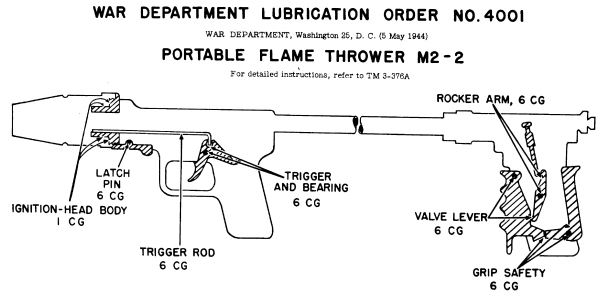
Fig 31. Lubrication order.
To requisition a replacement
Lubrication Order address
Office of the Chief, Chemical
Warfare Service, Washington
25, D. C.
NOT TO BE REPRODUCED
in whole or in part without permission
of the Office of the
Chief, Chemical Warfare Service.
NO. 4001
| ———— KEY ———— | |||
|---|---|---|---|
| LUBRICANTS | INTERVALS | ||
| CG- | GREASE, | 1- | AFTER EACH MISSION |
| GENERAL PURPOSE | 6- | AFTER SIX MISSIONS | |
| NO. 1 (ABOVE + 32°F) | OR MORE OFTEN | ||
| NO. O (BELOW + 32°F) | |||
|
THIS ORDER IS TO BE FASTENED TO INSIDE LID OF FLAME THROWER PACKING CHEST. | |||
Copy of this Lubrication Order will remain with the equipment at all
times; instructions contained therein are mandatory and supersede all
conflicting lubrication Instructions dated prior to 5 MAY 1944
By order of the Secretary of War:
G. C. Marshall, Chief of Staff.
Official:
J. A. Ulio,
Major General,
The Adjutant General.
Section XIII LUBRICATION
49. LUBRICATION.
a. Gun group. War Department Lubrication Order No. 4001
(Fig 31) shows the parts which require lubrication, the lubricants,
and the intervals.
(1) Lubricants. Grease, general purpose, No. 1 is used,
except for temperatures below freezing, when grease, general
purpose. No. 0 is used. The bearing surfaces should be lightly
coated with the grease.
(2) Frequency of lubrication. The surfaces of the ignition-head
body which touch the spring case should be lubricated after
each use of the weapon. Other parts are lubricated after six
firing missions, six training sessions, or oftener. All should
be thoroughly cleaned (Pars 52, 55, and 56) with gasoline,
dry cleaning solvent, or other solvent, then dried before lubrication.
If the gun is disassembled for any other reason, it should
be lubricated before reassembly.
(3) Records. To ascertain when six missions have been fired, a record
of firing (Par 2) should be kept with each flame thrower.
b. Tank group. The tank group ordinarily requires no lubrication.
However, it may under the following exceptional circumstances:
(1) If the tank group has been immersed in water for several hours,
the flexible shaft of the pressure valve may have lost its lubricant.
If so, remove the shaft (Par 66 b) and inspect. If lubricant is not
present, as indicated by difficulty of movement after removal, dip
the shaft in solvent to clean and then dip in warmed grease, general
purpose, No. 1. Replace shaft in valve.
(2) If filling or safety-head plugs (Figs 39 and 40) tend to stick
to fuel tanks, apply grease, general purpose, No. 1 (No. 0 if below
freezing temperatures) before replacing plugs.
Section XIV PREVENTIVE
MAINTENANCE SERVICES
50. GENERAL
Preventive maintenance services, as prescribed by Army Regulations,
are a function of using organization echelons of maintenance.
These services consist of:
a. Before, during, and after operation services performed by
the firers and assistants.
b. Scheduled services performed by organizational maintenance
personnel (service when filling and charging, and service
after six firing missions).
51. BEFORE-OPERATION SERVICE OF TANK GROUP.
The following services are to be performed before filling,
charging, and loading the flame thrower with pressure, fuel, and
ignition cylinder:
a. Pressure-tank valve. Open and close pressure-tank valve
to test for ease of operation.
b. Threaded connections. Check all threaded connections for
tightness, using appropriate wrenches.
c. Tank coupling. Examine coupling for cleanliness and ease
of movement of lock and cams. (Par 70) Clean if necessary.
If washer is broken, replace, using screw driver to pry out.
d. Plugs. Check filling plug and safety-head plug for completeness
of parts (Par 69 a) and cleanliness of threads and seats. Clean, if
necessary, with cloth. If rod or rod and chain have broken off and
fallen in tank, turn tank upside down and remove. Remove deflector
tube from head (using hand, not wrench). Inspect to see if diaphragm
is intact. If diaphragm is ruptured, replace the safety head with an
unbroken head. (Par 69 b, c) Reassemble plug, head, and deflector tube
in left fuel tank. (Fig 11) Tube should face to rear and at a 45-degree
angle to operator’s left shoulder. (Fig 18) Screw in deflector tube by
hand; do not use wrench on deflector tube. Tighten lock nut with wrench.
e. Pressure-tank clamp. The clamp should hold the pressure
tank tightly in place. If tank is loose, a wooden splint or wedge
under the clamp may be used as a temporary expedient.
f. Carrier-frame bolts. Check tightness. Use wrench.
g. Carrier. (Par 71) Examine all canvas, webbing, and cord
for signs of mildew, rot, or wear. Replace defective parts. Move
flame thrower to dryer storage if mildew occurs.
h. Cord (lashing). Check for tightness. If necessary, make
tighter and use secure, slip-proof knots. When the tank group
is filled with fuel and adjusted on the firer, its weight should be
carried chiefly by the canvas and webbing, not by the metal frame.
i. Shoulder and body straps. Adjust straps to fit firer. (Pars
19 and 71) A loose tank group can cause discomfort or injury
when the wearer changes positions while on a mission. Check
presence and condition of the two pins and two cotter pins which
hold shoulder straps to steel support. Check fasteners.
52. BEFORE-OPERATION SERVICE OF GUN GROUP.
The following services are to be performed before filling, charging,
and loading with pressure, fuel, and ignition cylinder:
a. Hose nipple, tank end. Examine to be sure nipple is clean
and not badly nicked. If badly nicked, the nipple may not make
a tight seal at the tank coupling. A leak and loss of pressure
may result. See Paragraph 73 d for repair of the nipple.
b. Fuel hose. Examine surface of hose for cracks or other signs of
deterioration. Special attention should be paid to portions adjacent to
the gun and tank coupling, which are subjected to severe flexing. If
hose is defective, replace. (Par 73 b, c) Do not patch.
c. Hose nipple, gun end. Check tightness of threaded connection
between hose and fuel-valve body, using hand or very light wrench
pressure.
d. Shield. Remove ignition shield. Check cleanliness of
threads on shield and on ignition-head body. If not clean, use
cloth. When reassembling (Par 18 c), shield should turn freely
until it locks in correct position.
e. Valve lever and needle.
(1) There should be some play in
the valve lever. To test, remove ignition shield. Compress grip
safety and valve lever slowly, observing the motion of the valve
needle. The valve lever should move approximately 1/16 inch
before the needle begins to move.
(2) Valve needle should be seated firmly in the barrel nozzle.
After the valve lever is pulled back and released, no play should
occur in the needle. For adjustment of needle, see Paragraph 75 d.
f. Screws. Use screw driver to test tightness of all screws.
g. Spring retainer and plug. Check tightness of spring retainer
and plug (Fig 47) by using hand or very light wrench pressure.
h. Ignition head. All exposed surfaces of the shield, nozzle,
needle, and other parts of the ignition head, or adjacent to it, should
be clean. If not, use cloth.
i. Atomizer hole. With the fuel valve held fully open, insert
a fine wire in the atomizer hole of the nozzle to clean the hole.
Then use cloth-wrapped splint to remove from the inside of the
nozzle any foreign matter pushed through the atomizer hole. If
such matter is not removed, it may interfere with the closing of
the fuel valve needle at the nozzle. Repeat procedure in e (2)
above.
j. Spring case. Spring case should turn freely on ignition head.
If it does not, clean any grease or dirt from, surfaces with cloth
and relubricate. (Par 49)
k. Trigger. Pull trigger once or twice to find whether it operates
easily and whether it returns to position. If not, clean and
lubricate trigger. (Par 49) Check condition of trigger spring.
l. Trigger rod. Check position of the trigger rod when trigger
is pulled back all the way as when firing. The rod should
extend approximately 1/16 inch beyond the end of the lug in the
ignition head. If it does not, bend the rod slightly, reverse position
of bearing, or replace worn parts.
53. SERVICE WHEN FILLING AND CHARGING.
a. Inspection of fuel tanks. Just before filling and charging,
remove plugs (Par 69 b) and examine interior of fuel tanks to see
whether they are clean and free from foreign matter. If not clean,
flush with gasoline until clean.
b. Fuel level. When filling (Pars 37 through 40), see that fuel
reaches the same level in both tanks. If leveling does not occur,
the tank connector may be clogged with foreign matter. If so, clean,
as in a, above. After filling, wipe plug seats with a cloth before
replacing plugs. Wipe any spilled fuel from weapon.
c. Pressure-tank valve. Before charging the tank group with
air or nitrogen, open and close the pressure-tank valve several
times by hand to be sure it operates freely. If it does not, adjust
as described in Paragraph 66 d.
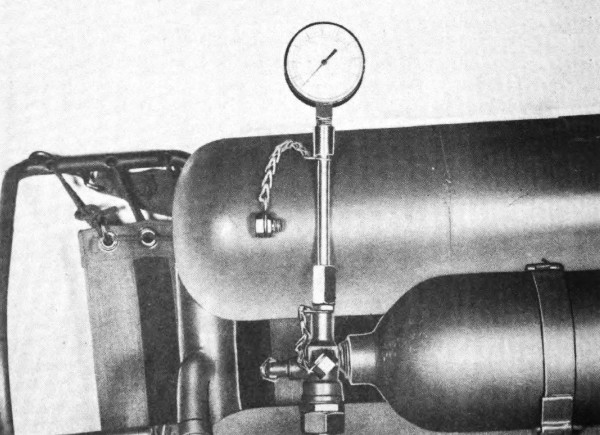
Fig 32. Testing pressure tank and valve, using 0-3,000-pound
testing gage from service kit.
d. Testing for leaks in pressure system. After charging, and
as few hours as possible before a mission, use an 0-3,000-pound
gage furnished in service kit to test pressure. (Fig 32) To install
gage, unscrew check-valve cap and screw gage in check-valve
body. If pressure has fallen below that to which the tank was
charged (Par 32), a leak is indicated. Remove gage, replace
check-valve cap, and check for leaks at joints between pressure
tank and valve and between tank valve and check valve. (A wrench
should be used to tighten cap on check-valve body so as to avoid
producing an additional leak.) Large leaks can be felt or heard.
Small leaks can be detected by coating joints with soap-and-water
solution. Bubbles indicate leaks. If a leak is revealed between53
pressure tank and pressure-tank valve, or between check valve
and pressure-tank valve, replace all three as a unit. If tests do
not show up the leak the tank may have been improperly charged.
It should be recharged and then retested.
54. SERVICE WHEN FIRING.
a. Failure to ignite. Pull trigger repeatedly. If ignition cylinder
still fails to ignite, dirt may be wedged in ignition head.
Unscrew shield one-half turn. Screw it back, rapping shield with
the hand while turning. This should dislodge foreign matter.
Pull trigger again. Repeat procedure, if necessary.
b. Safety head “blows” (breaks). If safety head breaks, firing
mission cannot be carried out. On return, have head replaced.
(Par 69) Follow test procedure. (Par 56 b)
55. SERVICE AFTER FIRING.
a. Unloading. Remove ignition cylinder (Par 30), close pressure-tank
valve, and blow out remaining fuel and pressure. (Par 30)
b. Removal of equipment. Release the body straps, then the
shoulder straps. If prone, lie on side and allow tank group to
roll off onto ground. If standing or kneeling, take care that tank
group does not drop on feet or legs.
c. Correcting or reporting. Correct any failures or difficulties
or report them as soon as possible to service or maintenance
personnel.
d. Gun. Remove shield (Par 18) and clean interior of shield
with cloth. Clean holes in shield with wire or wooden splint.
Clean external surfaces of barrel, nozzle, needle, and other parts.
Check cleanliness and adjustment of needle. (Par 75 d) Check
trigger for operation. Lubricate. (Par 49)
e. Fuel tanks and passages. Remove plugs (Par 69 b). Drain
any remaining fuel. Use gasoline to remove residues of thickened
fuels before they have a chance to harden and obstruct passages.
If necessary, fill tanks with gasoline and allow to stand
for several hours, shaking occasionally. Drain and repeat if
necessary.
f. Safety head. Check head to see if it is ruptured; if it is, replace.
(Par 69) Follow test procedure. (Par 56 b)
g. Pressure-tank valve. If weapon is to be stored, open
pressure-tank valve and leave it open until next charging.
h. Carrier. Scrub, if necessary, with soap and water, or
gasoline.
i. Exterior metal surfaces. Scrub exterior metal surfaces
clean of fuel to prevent fire hazard. Allow to dry before using
again.
j. General inspection. Carefully examine all other parts,
adjust as necessary, and replace any which are damaged.
56. SERVICE AFTER SIX FIRING MISSIONS.
After the flame thrower has been used on six firing missions
or the equivalent in training work, experienced personnel should
follow these directions:
a. Before-operation and after-operation service. Follow the
same procedures as in Paragraphs 52, 53, and 55.
b. Test firing (or simulated firing).
(1) If tactical conditions
permit test firing at a suitable test range (Par 15), fill the fuel
tanks with fuel. (Pars 37 through 40)
(2) If test firing with fuel is impracticable, fill fuel tanks with
clean water. (Be sure to dry all parts after test.)
(3) Remove filling-plug assembly. (Par 69) Fish out the retainer
rod and chain by means of a bent wire.
(4) Do not unscrew the safety-head plug.
(5) Insert the testing plug with 0-to 500-pound pressure gage
(plug and gage are from service kit) in the filling-plug opening.
Tighten testing plug in seat with wrench.
(6) Fully charge pressure tank. (Par 32)
(7) If test firing with fuel, load ignition cylinder. (Par 18)
(8) Open pressure-tank valve and simultaneously observe
pressure in fuel tanks by reading gage. The gage indicates the
pressure in both tanks. It should be between 350 and 390 pounds
per square inch.
(9) Read the gage at the expiration of not less than 5 minutes.
The tanks should have a pressure reading of not more than 390
pounds. If the pressure continues to increase beyond 390 pounds
and the safety head blows, replace the safety head and the pressure
regulator.
(10) Fire by operating controls (or simulate firing if tanks are
filled with water). The burst should last 3 seconds, during which
time the pressure should not drop below 260 pounds.
(11) If the pressure does not conform to the requirements
stated in (8), (9), and (10), adjust the pressure regulator upward
or downward. (Par 67 d)
(12) While the above test firing is proceeding, check for leaks
at all joints and connections on the tank group. The pressure
system should be checked by painting the joints with soap-and-water
solution and by looking for bubbles which indicate leaks.
For replacement of parts where pressure leaks, see Paragraph
66. Fuel leaks may be seen without soap and water. For repair
of fuel leaks, see Paragraph 75 e. The nozzle should be
observed by removing the ignition shield. Nozzle leaks are corrected
by cleaning, adjusting needle (Par 75 d), or by regrinding.
(Par 75 e) If this is not successful, replace both needle and barrel
as a unit.
c. Fuel valve. Discharge all pressure from the gun by operating
the fuel valve. Carefully remove the valve grip and grip
support. (Par 74) Look for signs of leakage at the valve diaphragm.55
If a leak is present, replace valve-diaphragm assembly.
(Pars 75 b and 75 c)
d. Valve grip. Disassemble the valve grip (Par 74) and lubricate.
(Par 49)
e. Carrier. Tighten the carrier cord.
f. Gun interior. If thickened fuel has been fired, disassemble
the gun. All parts should be cleaned of accumulations of
dried fuel. Lubricate (Par 49) and reassemble. If liquid fuel
has been fired, flush gun with clean gasoline. Disassemble only
enough to lubricate. Reassemble.
Section XV
TROUBLE SHOOTING
57. PRECAUTIONS.
First, remove the ignition cylinder. Then, before disassembling,
servicing, or repairing parts which may be under pressure, be
sure to release the pressure. Remove fuel, when necessary.
58. FUEL LEAKS.
| Trouble | Remedy |
|---|---|
| a. Defective or damaged valve-diaphragm assembly. | If leak is observed in valve grip, |
| b. Defective threaded connections on fuel lines. | Disconnect, using wrenches. If |
| c. Dirt or foreign matter on seats or threads. | Clean parts carefully with cloth |
| d. Leak at nozzle. | Adjust needle. (Par 75 d) |
| e. Worn body of hose.56 | Replace fuel-hose assembly. (Par 73) |
| f. Leak at tank coupling. | Remove and replace coupling washer if |
59. SAFETY HEAD “BLOWS” (BREAKS).
| Trouble | Remedy |
|---|---|
| a. Defective safety head. | Replace with new safety head. |
| b. Defective pressure regulator. | If replacement safety head also |
60. CARRIER UNCOMFORTABLE.
| Trouble | Remedy |
|---|---|
| a. Cord becomes loose or breaks. | Use only hard-braided seine |
| b. Straps not adjusted to fit wearer. | Adjust straps to fit each new |
| c. Carrier frame presses on wearer’s back. | Cord is too loose. Tighten |
61. SHORT RANGE.
| Trouble | Remedy |
|---|---|
| a. Stream of burning fuel issues at an angle or in a very broad spray. | Fuel valve is not fully open because of: (1) Faulty operation. Be sure to compress controls (2) Improper adjustment or assembly of valve. To |
| b. Rapid drop of range during a burst. | Pressure-tank valve is not |
| c. Shorter range in each successive burst. | Pressure tank is not fully charged. (1) Before firing be sure tank is (2) Check for leaks to make sure |
| d. Short range with longer time of discharge than 8 to 9 seconds. | Dried fuel or other foreign |
62. FUEL-VALVE FAILURE.
| Trouble | Remedy |
|---|---|
| Valve fails to close when controls are released. | (1) Work the (2) Foreign matter may be in barrel, or barrel may be |
63. FAILURE OF IGNITION CYLINDER TO IGNITE.
| Trouble | Remedy |
|---|---|
| a. Match in cylinder moves but incendiary charge does not ignite. | Pull trigger repeatedly. If (1) If matches have been pushed flush with inner (2) If matches project 1/16 inch or more from |
| b. Cylinder does not rotate to bring new charge into position. | (1) Spring case is not free to (2) Cylinder is improperly loaded. (Par 18) (3) Ignition cylinder binds on barrel because of (4) Spring case is defective. Replace as a unit. |
| c. Trigger does not return to normal position (with ignition cylinder in place). | 1) When on a mission, use (2) If time permits, remove trigger rod. (Par 76 b) Clean rod and hole in which rod slides. |
| d. Lack of spring tension at trigger. | Trigger spring is off hook of |
64. FAILURE OF FUEL TO IGNITE.
| Trouble | Remedy |
|---|---|
| a. Atomizer hole clogged. | Clean with fine wire. (Par 52 i) |
| b. Fuel troubles at low temperature. | (1) At temperatures below minus (2) At temperatures above minus 20 degrees |
| c. Failure of ignition cylinder. | See Paragraph 63. |
Section XVI
TANK GROUP
65. GENERAL.
The tank group stores fuel and pressure. The fuel is placed under
pressure when the pressure-tank valve is opened. The tank
group is supported upon the firer’s back and shoulders by the
carrier.
66. PRESSURE TANK AND VALVE ASSEMBLY.
a. Description and functioning. The pressure tank and valve
assembly (Fig 33) includes:
(1) Pressure tank. The pressure tank is a lightweight, airplane-type
cylinder, able to withstand the great pressure which
it contains. The tank is charged with air or nitrogen at 1,700 to
2,100 pounds per square inch pressure by use of auxiliary equipment
as described in Paragraphs 31 and 32. This pressure stays
in the pressure tank until the weapon is ready to be fired. Opening
of the pressure-tank valve releases air or nitrogen through
the pressure regulator to the fuel tanks. Oxygen or combustible
gases are never used in the tank because a violent explosion may
result. The tank is large in capacity to assure ample pressure,
and hence full range, for the entire load of fuel. The pressure-tank
clamp (Fig 39), a steel-strap device with hinge and toggle-type
latch, holds the pressure tank in place on the fuel tanks.
(2) Pressure-tank valve. (Figs 33 and 34) This valve is
screwed into the bottom of the pressure tank. The valve stem
slides into the valve end of the valve flexible shaft. When opened
by means of the valve handle and valve flexible shaft, the valve
permits passage of compressed air or nitrogen through tubes
and the pressure regulator to the fuel tanks. The valve is of the
quick-opening, packless, diaphragm type.
(3) Pressure-valve handle and valve flexible shaft. (Figs 33
and 34) The pressure-valve handle is held by a small nut on the
end of the valve flexible shaft, which in turn is connected to the
pressure-tank valve by means of the valve stem and a large hex
nut. The handle and shaft extend to the right of the tank group,
enabling the firer to open and close the valve without assistance
when carrying the weapon. The handle slips over the end of the
shaft and is held to it by a nut. The shaft is held to one of the
fuel tanks by a clamp, nut, and bolt welded to the tank.
(4) Check valve. (Figs 33 through 35) The check valve has
the same function as the valve on a vehicular tire tube, but it is
much heavier in construction and different in design because the
pressure in the flame thrower is 50 times greater than that in an
automobile tire tube. Connected by threads to the pressure valve,
the check valve permits compressed air or nitrogen to enter the
pressure tank during charging (Pars 31 and 32) but prevents
its escape when the outside source of pressure is removed. The
cap is removed from the check valve only for charging or testing.
b. Removal. (Fig 33) To prevent damage to threads, leaks,
and loss of pressure and range, remove pressure tank and valve
assembly only when necessary.
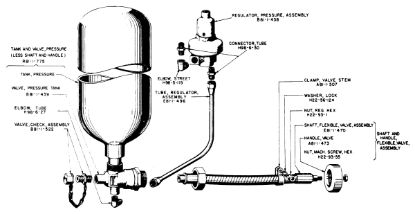
Fig 33. Pressure system disassembled, showing
nomenclature and Chemical Warfare Service stock numbers for
requisitioning spare parts.
(1) Release of pressure. Be sure all pressure has been released
from the pressure system before disassembling or removing
any part or assembly of the pressure system. To release
pressure, operate fuel valve (Par 26) and hold open until61
pressure is exhausted. As an added precaution, personnel should
avoid facing the connections when disconnecting parts or assemblies.
(2) Removal procedure. After release of all pressure:
(a) Loosen the clamp from the valve flexible shaft.
(b) Using wrench, unscrew the large hex nut which holds
the flexible shaft on the pressure-tank valve.
(c) Pull the valve flexible shaft and handle free of the valve.
(d) Using wrench, unscrew the flared tube nut on the regulator
tube adjacent to the pressure-tank valve.
(e) Open pressure-tank clamp (Fig 39) and swing clamp
strap outward.
(f) Remove the pressure tank together with the pressure-tank
valve and check valve.
(g) To remove valve handle, use the adjustable-end wrench
to loosen and remove nut from threaded outer end of valve flexible
shaft. Slide out the valve handle.
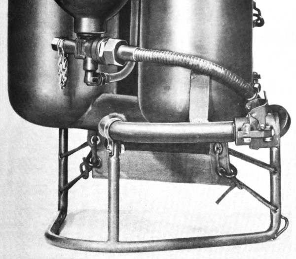
Fig 34. Lower portion of pressure system, assembled.
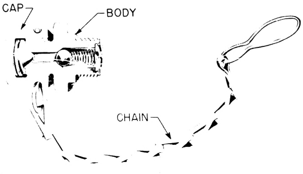
Fig 35. Check valve (cross section).
c. Installation. (Figs 33 and 39) To install:
(1) Insert pressure tank (with pressure-tank valve and check
valve mounted on the tank) through the pressure-tank clamp. Be
sure to aline the regulator tube, elbow, and pressure-tank valve
threads carefully so that they cannot be damaged when connecting.
(2) Close the pressure-tank clamp.
(3) Start the threaded connections by hand to be sure they are
well alined. Do not force. Use wrench for final tightening, but do
not apply great torque to the wrench.
(4) Insert the valve flexible shaft through small clamp into
the pressure-tank valve. Using wrench, tighten the large hex
nut located between shaft and valve.
(5) Tighten the clamp on the valve flexible shaft.
(6) Place pressure-valve handle on threaded end of the shaft.
Place nut on threaded end and tighten with adjustable-end wrench.
d. Adjustment. If valve handle cannot be turned by hand:
(1) Remove flexible shaft and handle. Never apply a wrench
to these parts.
(2) Turn end of pressure-valve stem with wrench to open
valve.
(3) If stem will not turn, replace the tank and valve.
(4) If stem turns, work it back and forth with wrench.
(5) Reconnect flexible shaft and handle.
(6) If handle does not turn easily, repeat the process until
handle turns, or replace tank and valve.
(7) Close valve before charging tank.
e. Maintenance.
(1) If either pressure tank, pressure-tank valve, or check
valve are damaged or defective, all three must be replaced as a
unit. No attempt may be made to repair any of these parts or63
their connections. If makeshift repairs or improvised parts are
devised, serious accidents can result because of the extremely
high pressures to which the equipment is subjected.
(2) Keep all threaded connections tightened. If a leak is suspected
at any threaded connection, follow procedure in Paragraph
53 d.
67. PRESSURE REGULATOR.
a. Description and functioning. The regulator automatically
reduces the variable pressure of air or nitrogen in the pressure
tank to a constant operating pressure of approximately 350 pounds
per square inch in the fuel tanks. The regulator is located at a
protected position in the tank group of the M2-2 portable flame
thrower, where it is not readily subject to tampering or damage
from the outside. The regulator tube with fittings connects the
pressure-tank valve and pressure regulator. (Fig 33) Its outlet
is connected to the fuel tanks by the diffusion-pipe assembly.
(Par 68 a) Either of two interchangeable types of regulators
is furnished: the spring type (Figs 33, 36, and 37), and the
dome type (Fig 38).
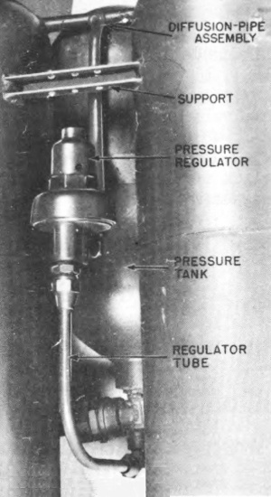
Fig 36. Rear of tank group, with carrier removed to show
pressure regulator (spring-type) and connections.
b. Removal of pressure regulator. After release of all pressure:
(1) Remove carrier (Par 71 b), if necessary.
(2) Using wrench, unscrew the flared tube nuts and other fittings.
(3) Lift out the pressure regulator.
c. Installation of pressure regulator. Line up pressure regulator,
regulator tube, diffusion-pipe assembly, and fittings carefully so they
will not be damaged when threads are tightened. Start threads with the
hands. Apply only moderate wrench pressure to complete tightening.
Replace carrier or carrier pack if either has been removed.
d. Adjustment of pressure regulator. The pressure regulator
ordinarily requires no attention other than checking and tightening
connections with the regulator tube and the diffusion-pipe64 assembly.
If a defect in the regulator is indicated by falling off of the range
of the weapon or by frequent breakage of the safety-head diaphragm (Par 56 b),
the following procedure should be carried out. (When using
wrenches, do not apply excessive force.)
(1) Remove the filling plug (Par 69 b) and ignition cylinder.
(Par 30 a)
(2) Fill the fuel tanks with 4 gallons of water (or fuel).
(3) Connect the 0-to 500-pound fuel-tank testing gage, found in the
service kit, to the filling-plug hole. Tighten plug of gage with wrench.
(4) Charge the pressure tank to a pressure of 1,800 pounds per square
inch. (Pars 32 and 33)
(5) Open the pressure-tank valve.
(6) Read the pressure on the gage. If 350 to 390 pounds is indicated,
omit steps (7) through (10).
(7) To increase the pressure of a spring-type regulator:
(a) Pry off the protective cap.
(b) Turn a set-screw wrench clockwise in the adjusting screw and read
pressure on gage.
(8) To decrease the pressure of a spring-type regulator:
(a) Turn the set-screw wrench counterclockwise more than is
considered sufficient to effect the desired reduction.
(b) Turn the pressure-tank valve off.
(c) Relieve pressure in the fuel tanks by compressing the fuel valve
until the pressure is below that desired.
(d) Release the fuel valve.
(e) Open the pressure-tank valve and allow the system to reach a
state of equilibrium, which occurs when the hissing sound ceases.
(f) Repeat the steps described above in (6) and (7).
(9) To increase the pressure of a dome-type regulator:
(a) Open needle valve No. 1 one full turn. (Fig 38)
(b) Open needle valve No. 2 one full turn. (There will be slight
leakage around the needle-valve thread.)
(c) Open needle valve No. 3 very slowly, watching pressure gage
closely. (As pressure builds up in fuel tanks there will be slight
leakage through needle valve No. 1.)
(d) When the pressure gage indicates 350 pounds, close needle valve
No. 3 tight.
(e) Close needle valve No. 2 tight.
(f) Close pressure-tank valve.
(g) When gage indicates zero, close needle valve No. 1 tight.
(10) To decrease the pressure of a dome-type regulator:
(a) Open needle valve No. 1 one full turn. (Fig 38)
(b) Open needle valve No. 3 very slightly, which will lower the
pressure.
(c) When 350 pounds is reached, close valve No. 3 tight.
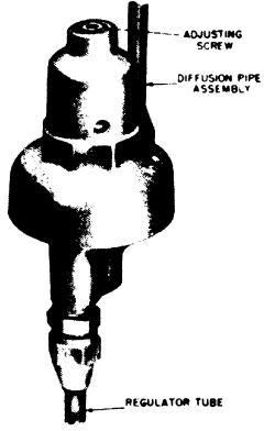
Fig 37. Pressure regulator, spring-type.
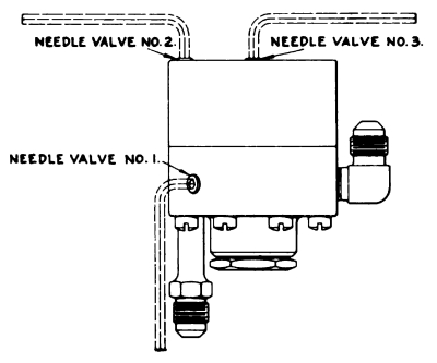
Fig 38. Pressure regulator, dome-type, showing needle
valves and wrenches.
(d) Close pressure-tank valve.
(e) When gage indicates zero, close needle valve No. 1 tight.
(11) Open pressure-tank valve and press the fuel valve to observe the
pressure with the weapon operating.
(12) After final adjustment:
(a) Close the pressure-tank valve.
(b) Open the fuel valve and release the pressure from the fuel tanks.
(c) Remove the pressure gage and plug from the fuel tank.
(d) Install filling plug.
(e) Tighten filling plug with wrench.
(f) If regulator is spring-type, replace its protective cap.
68. FUEL-TANK ASSEMBLY.
a. Description and functioning. (Figs 4, 5, and 39) The fuel-tank
assembly includes:
(1) Fuel tanks. Two alloy steel fuel tanks hold the fuel before it
is propelled to the target. They have a combined capacity, including
void, of 4-1/2 gallons. A void of approximately 1/2 gallon is left in
tanks when filling to allow for expansion and to permit entry of the
compressed nitrogen or air. To speed filling and cleaning of the tanks,
two openings are provided on top of the fuel tanks. The openings are
threaded to receive the filling-plug assembly and the safety-head plug
assembly, which are interchangeable in the openings. Filling operations
involve the use of auxiliary equipment and are described in Paragraphs
34 through 40. The carrier and the pressure system are supported on the
fuel tanks.
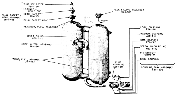
Fig 39. Fuel system of tank group and related parts
disassembled, showing nomenclature and Chemical Warfare Service stock
numbers for requisitioning spare parts.
(2) Tank connector. This open passageway between the fuel tanks
makes them, in effect, a single container. The location of the67 tank
connector and its large diameter permit easy flow of fuel and pressure
between the two tanks.
(3) Hose connector. The hose connector is the outlet for fuel from
the fuel tanks. It is located so that nearly all the fuel is propelled
from the weapon if firing positions are correct. (Par 24) One end is
welded to an opening in the tank connector. The other end is threaded
into the tank coupling.
(4) Frame clamp. This small metal clamp, with bolt, nut, and washer,
holds the hose connector to the carrier frame.
(5) Diffusion-pipe assembly. This T-shaped tubing carries compressed
air or nitrogen from the pressure regulator to each of the fuel tanks.
A flared tube connection and elbow connect the stem of the T to the
pressure regulator. The horizontal tubes of the T extend into the fuel
tanks and are welded to the fuel tank walls. Within the fuel tanks
these tubes are perforated with holes which permit ready escape of the
compressed nitrogen or air into the fuel tanks when the pressure-tank
valve is open.
b. Removal and installation. The tank connector, hose connector,
diffusion-pipe assembly, and the two fuel tanks are welded together and
cannot be disassembled from each other. No attempt should be made to
remove any of these parts or assemblies.
c. Maintenance. Other than cleaning (Pars 51 d and 55 e),
repainting, and tightening of threaded joints, no repairs will be
attempted by the first or second echelon on the fuel tanks, tank and
hose connectors, or diffusion-pipe assembly. Emergency repairs may be
made only by the third or fourth echelon. No attempt should be made to
weld or patch any part of the fuel tanks.
69. FILLING AND SAFETY-HEAD PLUG ASSEMBLIES.
a. Description and functioning.
(1) Filling-plug assembly. (Fig 39) This assembly fits into the
1-3/8-inch threaded opening at the top of either one of the fuel tanks.
It permits filling and cleaning of the tanks, and seals the opening
when the tank is not being filled or cleaned. The assembly includes
the filling plug proper and a plug-retainer assembly. The latter is a
metal rod which hangs from the plug on a metal chain. The rod and chain
prevent accidental loss of the plug.
(2) Safety-head plug assembly. (Figs 39 and 40) This assembly is
screwed into the threaded opening on top of either fuel tank. It serves
the same functions as the filling-plug assembly and moreover protects
the firer and other personnel. It includes:
(a) Safety-head plug. This plug is similar to the filling plug
except for the threaded hole which receives the safety head.
(b) Safety head. This metal head screws into the safety-head plug.
It includes a soft metal diaphragm which bursts when the pressure in
the fuel tanks exceeds 500 pounds per square inch.68 It prevents the
building up of dangerous pressures in the fuel tanks.
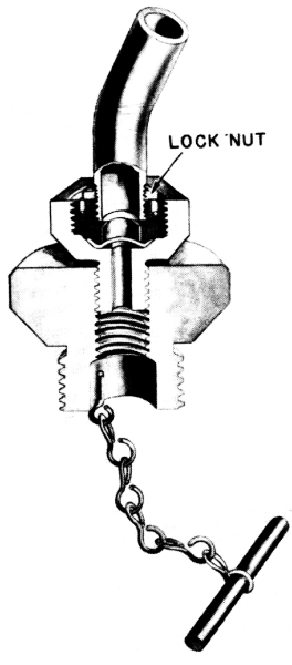
Fig 40. Safety-head plug assembly (cross section).
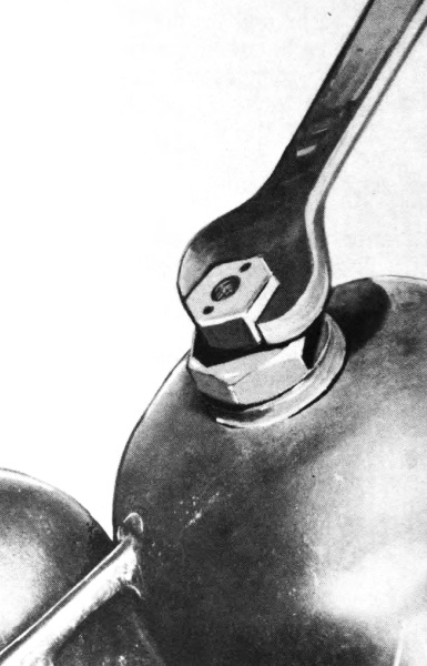
Fig 41. Unscrewing safety head from safety-head plug,
using wrench.
(c) Deflector tube. This short, curved piece of 1/8-inch pipe
deflects fuel and pressure away from the firer if the safety head
bursts. A lock nut holds the tube in position. (Par 12 j)
(d) Plug-retainer assembly. This assembly consists of a metal rod
and chain which hang from the plug and prevent accidental loss of the
plug when filling or inspecting.
b. Removal of plugs.
(1) Before removing the filling plug, the safety-head plug, or an
unbroken safety head, operate the fuel valve until any pressure which
may have accumulated in the fuel tanks is eliminated. If the coupling
plug is in the tank coupling, very slightly loosen the threads of
either the filling plug or the safety-head plug, using the 1-3/4-inch
wrench, to eliminate pressure in the fuel tanks. Keep face and eyes
away from the threads.
(2) The plug-retainer assemblies should not be lifted completely out of
the tanks unless required.
(3) If either the rod or the rod and chain breaks from one of the plugs
and falls into the tank, upend the tank group to permit removal of the
parts.
(4) To replace burst safety head, unscrew lock nut and deflector tube.
(Fig 11) Using wrench (Fig 41), unscrew safety head. Never disassemble
the safety head.
c. Installation of plugs. The filling plug, safety-head plug, and
safety head are screwed in by hand and then tightened with wrenches. No
substitution will be made for the safety head, which is manufactured
to burst at the safe limit of pressure. The plug threads and seats
should be cleaned with a cloth (Fig 29) before installing plugs. Screw
in deflector tube, using hand pressure. The tube outlet should face to
the rear and at a 45-degree angle to operator’s left shoulder. (Fig 18)
Replace lock nut and tighten with wrench. (Use wrench on lock nut, not
on deflector tube.)
d. Maintenance of plugs. Replace safety head if damaged or blown.
Never repair safety head or use an improvised head.
70. TANK COUPLING.
a. Description and functioning. This quick-connecting
coupling (Fig 42) connects and locks the fuel hose or the coupling plug to the tank
group. The coupling cams, lock, and washer provide a secure and tight
joint. The tank coupling makes possible rapid replacement of emptied
tank groups with filled and charged tank groups in the field. No tools
are needed for this operation.
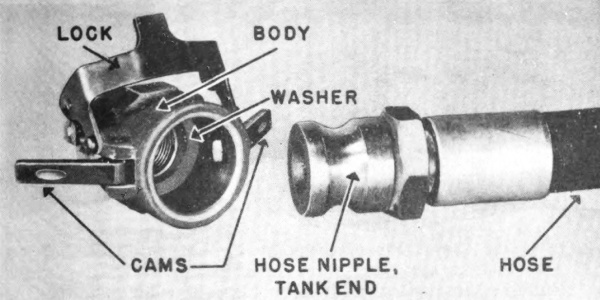
Fig 42. Tank coupling and end of fuel-hose assembly.
b. Removal.
(1) To remove the tank coupling from the hose connector, apply a wrench
and unscrew.
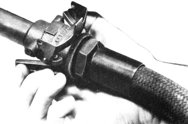
Fig 43. Closing cams of tank coupling to connect gun and
tank group. This is done before locking. (See below.)
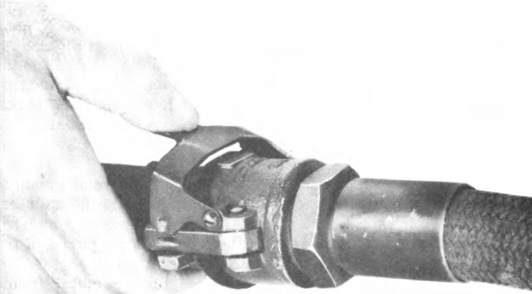
Fig 44. Closing lock of tank coupling to secure gun to
tank group. This also provides a fuel-tight seal.
(2) To disconnect the tank coupling from the fuel hose or the coupling
plug:
(a) Release pressure from fuel tanks by operating the fuel71 valve or
by opening very slightly the filling plug.
(b) Using hands, pivot the coupling lock back on the coupling body.
(c) Using hands, pivot the two coupling cams back on the coupling.
(d) Slide out the fuel hose or the tank coupling.
(e) If coupling washer is to be removed, pry out with a screw driver.
c. Installation of tank coupling. Proceed as follows:
(1) If coupling washer has been removed, replace.
(2) Insert coupling plug or hose nipple, tank end, in the coupling as
far as it will reach. Close the two cams. (Fig 43)
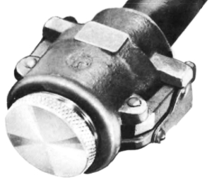
Fig 45. Coupling plug in place in tank coupling. This
arrangement is used when fuel tanks are brought back for filling with
gun detached.
(3) Close the coupling lock (Fig 44), being sure to push it all the
way, until it covers the ends of both cams. (Figure 45 shows coupling
lock correctly locked on coupling plug.)
(4) If the tank coupling has been removed from the hose connector,
screw it on hand tight. Anti-seize compound should be applied lightly
to the threads to assure a tight joint. Use wrench to tighten the
coupling until it is in the position shown in Figure 34.
d. Maintenance of tank coupling. The coupling washer, made of
synthetic rubber, should be inspected frequently. If it is damaged or
swollen, remove it and replace. If the coupling leaks, inspect, and if
necessary, remove and replace the washer.
71. CARRIER.
a. Description and functioning. (Fig 46) The tank group is securely
carried on the firer’s back and chest by the carrier, which includes
the metal carrier frame, the canvas carrier pack, webbing straps, and
cord, all of which are parts of the tank group.
(1) Carrier frame. This lightweight, tubular-metal frame is bolted to
two pairs of brackets (upper and lower) on the fuel tanks. It is also
bolted to the hose connector by the frame clamp, which helps support
the connector. The frame is pierced by two parallel series of holes,
through which the cord (lashing) of the carrier is laced.
(2) Carrier pack. This is a sheet of heavy canvas, reinforced on the
tank side with strips of webbing. The smooth side of the72 carrier pack
rests against the firer’s back and cushions the back from contact with
the metal tanks. A series of eyelets is located on each side of the
pack.
(3) Seine cord (lashing). The carrier pack is fastened to the carrier
frame by means of hard-braided cord which is laced through the eyelets
in the pack and the holes in the frame. The cord that comes on the
flame thrower stretches very little under load.
(4) Straps. The straps, made of wide cotton webbing, are
adjustable to fit the wearer. (Fig 18) They are provided with snap
release, hook-and-eye, and snap fasteners. The shoulder straps have
quick-release fasteners for rapid removal, if necessary, of the tank
group from the firer. The upper ends (steel loops) of the shoulder
straps are secured by pins to the steel support which connects the two
fuel tanks. Each of the pins is held in position by a split cotter pin,
which is inserted through a hole in the pin and is then spread. The
lower ends of the shoulder straps snap onto metal loops at the bottom
of the carrier frame. The upper body straps are attached to metal loops
on each side of the carrier frame. The lower body straps are fastened
to one of the lower two pairs of eyelets of the carrier pack.
b. Removal of carrier.
(1) To remove carrier or carrier frame, use screw driver and
adjustable-end wrench to take off frame clamp, bolt, nut, and lock
washer. (Fig 34) Then remove two pairs of bolts, nuts, and lock washers
which hold the carrier frame to bottom and top of the fuel tanks. Lift
off the carrier.
(2) To remove body straps, unsnap ends and lift out of holes. To remove
shoulder straps, unsnap lower ends and remove from holes. Pull out
cotter pins, then pins, from upper ends of shoulder straps, and lift
out straps.
(3) To remove carrier pack, unknot and unlace cord.
c. Installation of carrier.
(1) To install carrier frame (or a complete carrier) place frame in
position adjacent to fuel tanks (Fig 46), insert bolts in holes, place
lock washers and nuts on bolts, and tighten with screw driver and
wrench. Replace frame clamp on fuel connector and frame. Insert bolt in
holes, place lock washer and nut on bolt. Tighten with screw driver and
wrench.
(2) If carrier pack has been removed, use cord to relash. Lace tight
and use slip-proof knots. (Fig 46)
(3) To install straps, snap ends of body straps and lower ends of
shoulder straps into positions shown in Figure 46. Place upper ends
(steel loops) of shoulder straps in steel support between fuel tanks.
Insert two pins through any two of the holes in the support and through
the shoulder strap loops. Insert cotter pins in holes in pins and
spread cotter pins to lock pins in place.
d. Adjustment of carrier. Carrier must be carefully adjusted to fit
the individual firer so the load will not shift during sudden,73 rapid
changes of firer’s position. Adjustments are as follows:
(1) Cord and carrier pack. Cord must be tight at all times. The cord
furnished with the equipment has very little tendency to stretch.
However, pull cord tight when lacing and use slip-proof knots at ends.
Tighten cord periodically.
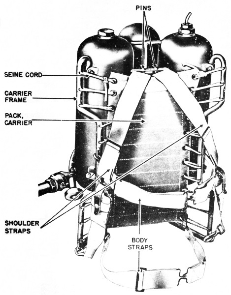
Fig 46. Carrier assembled on tank group.
(2) Straps. Adjust straps to fit each firer, moving slides on straps
as necessary. Straps must fit snugly to prevent shifting of load and to
keep tank group high on firer’s back. Lower body straps may be fastened
in second pair from the bottom of carrier74 eyelets to conform to
firer’s physique. Pins, which hold top ends of shoulder straps to steel
support between the fuel tanks, may be moved to any two of the three
holes so as to provide the best balance in the load.
e. Maintenance of carrier. Keep carrier dry and clean. If flame
thrower becomes wet or muddy, clean and dry carrier thoroughly. Store
in a dry place. If rotted, mildewed, or damaged, replace affected
parts. If cord frays or breaks, use special seine cord from service kit
as replacement.
Section XVII GUN GROUP
72. GENERAL
The gun group consists of the fuel-hose assembly and the gun. The gun
includes the fuel valve, which controls the ejection of fuel, and the
ignition head, which ignites the fuel.
73. FUEL-HOSE ASSEMBLY.
a. Description and functioning. (Fig 47) Hose, fuel, flame thrower,
M1, assembly, provides a flexible connection between the fuel tanks and
the gun.
(1) Hose. Made of synthetic rubber and reinforced with a cover of
metal wire and cotton braid, the hose resists the action of gasoline
and oil, and withstands a pressure of approximately 1,000 pounds per
square inch. Its inside diameter is 7/8 inch; its outside diameter is
approximately 1-1/4 inches.
(2) Nipples. The hose nipple, tank end, connects the hose to the tank
coupling on the tank group. The hose nipple, gun end, is a threaded
connector between the other end of the hose and the fuel-valve body.
b. Removal of fuel-hose assembly. Remove the hose from the gun only
when necessary for maintenance. The threads in the fuel-valve body will
be damaged by frequent screwing and unscrewing of the hose because the
body is a lightweight aluminum casting. Fuel hose is replaced as a unit
and is not disassembled in the second echelon. To disconnect from tank
group, see Paragraph 70 b.
c. Installation of fuel-hose assembly.
(1) To install in tank group, see Paragraph 70 c.
(2) To install in gun, apply anti-seize compound (from service kit)
lightly to threads and screw hose in fuel-valve body by hand. Use
wrench only enough to make a secure connection.
d. Maintenance of fuel-hose assembly. If the hose nipple, tank end,
is badly nicked and does not provide a tight connection75 with a new
coupling washer (Par 70):
(1) File the end surface, being careful to keep the surface at a right
angle to the sides of the nipple.
(2) Couple hose nipple, tank end, to tank coupling. If coupling closes
very easily, indicating washer is not being compressed, replace the
washer and recouple. If coupling still closes too freely, the nipple
has been filed too short, and the fuel-hose assembly should be replaced
as a unit.
74. VALVE GRIP.
a. Description and functioning. (Fig 47) The valve grip is part of
the fuel valve. It includes the controls and is held by the firer in
his right hand to support the gun group. Parts of the valve grip are:
(1) Left and right valve grips. A pistol-type grip is formed by two
aluminum housings designated as the left valve grip and the right valve
grip. The two parts are held together by four screws and four lock
washers.
(2) Grip support. This aluminum housing is mounted above the left and
right valve grips and connected to them by two screws and lock washers.
(3) Valve lever. This control is made to fit the fingers and is
mounted in front of and between the two parts of the valve grip. A
pin at the top of the lever fits into holes in left and right valve
grips and serves as a pivot, governing the movement of the lever. When
the lever and the grip safety are compressed simultaneously by the
operator, the valve is thereby opened and fuel is ejected from the gun.
(4) Grip safety. This control is grasped by the hand simultaneously
with the valve lever. It is mounted back of and between left and right
valve grips. A pin at the base of the safety fits into holes in the
left and right valve grips and serves as a pivot in a manner similar to
the pin on the valve lever. The fuel cannot be discharged unless both
the valve lever and the grip safety are compressed simultaneously.
(5) Rocker arm. The rocker arm, a boat-shaped metal part, is mounted
near its center on a pin. It is held in contact with the valve lever by
means of a valve-grip spring and spring pin. At its top end, the rocker
arm touches the yoke shaft of the valve-diaphragm assembly. When the
valve lever and the grip safety are compressed, the rocker arm pushes
the valve diaphragm assembly forward.
(6) Valve-grip spring. When the firer’s hand releases the valve grip,
the valve-grip spring forces the valve lever, the grip safety, and the
rocker arm back to their normal, nonoperating positions.
b. Removal of valve grip.
(1) Unscrew the four screws and lock washers that hold the grip support
to the valve body. Remove the valve grip as a unit.
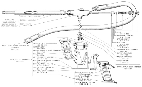
Fig 47. Fuel valve (disassembled) and fuel hose,
showing nomenclature and Chemical Warfare Service stock numbers for
requisitioning spare parts.
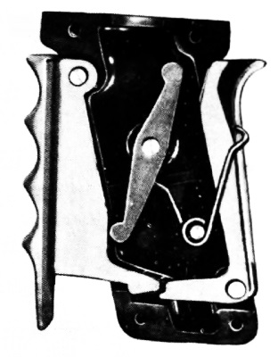
Fig 48. Location of parts in right valve grip before
covering them with left valve grip.
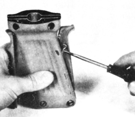
Fig 49. Using screw driver to push long end of
valve-grip spring into groove in grip safety.
(2) To disassemble valve grip, remove screws and lock washers from the
grip. Lift off the left valve grip, exposing contents of grip. Lift out
the following parts: valve-grip spring, rocker arm, grip safety, and
valve lever.
c. Installing valve grip.
(1) Place grip safety, valve lever, and rocker arm in position in right
valve grip. (Fig 48) Be sure the shorter end of rocker arm is at the
top. Place grip spring over spring pin. Slip short end of grip spring
in groove of rocker arm. Place long end of grip spring on outside of
grip safety.
(2) Put left valve grip in place and insert the two lower lock washers
and screws. Tighten the two screws enough to hold parts in place and
still leave space for moving long end of spring into the groove in grip
safety. Push spring into groove with a screw driver. (Fig 49)
(3) With spring in place, fully tighten the two screws with screw
driver.
(4) Place grip support in position, and insert the two upper lock
washers and screws. Tighten screws, using screw driver.
(5) Attach valve grip to valve body, using the four lock washers and
inserting the four screws through the grip support. Make sure that the
yoke shaft of the valve-diaphragm assembly is in front of rocker arm.
d. Maintenance of valve grip. No maintenance is required for the
valve grip other than replacement of worn or damaged parts, tightening
of screws, cleaning, and lubrication. (Par 49)
75. BARREL AND VALVE-BODY ASSEMBLY.
a. Description and functioning. (Fig 47) This assembly is part of the
fuel valve. It includes the barrel, valve body, and78 operating parts
contained in the barrel and valve body. The assembly consists of:
(1) Valve body, an aluminum housing, located at the rear of the
gun and mounted on the grip support by means of four screws and lock
washers. The valve body has four large threaded openings. The lower
opening leads into the valve grip. The side opening, which forms a
Y with the main portion of the body, is connected to the fuel-hose
assembly. The front opening is screwed on the barrel. The rear opening
is closed by the spring retainer and plug.
(2) Valve-diaphragm assembly, which transmits and reverses the
movement imparted to it by the rocker arm of the valve grip. (Par 74 a)
It also serves as a seal, keeping fuel from entering the valve
grip. The valve-diaphragm assembly includes:
(a) Yoke shaft, on which the rocker arm bears at the lower end of
the shaft.
(b) Yoke, a Y-shaped metal part which fits on the upper end of the
yoke shaft and is held to it by a steel pin. The yoke transmits motion
from the shaft to the yoke block, and is located within the valve body
when the valve is assembled.
(c) Diaphragm, a synthetic-rubber diaphragm held in a steel sleeve,
which fits snugly in the lower opening of the valve body. The yoke
shaft passes through the diaphragm.
(3) Diaphragm support, washer, and cap, which hold the
valve-diaphragm assembly in place in the valve body.
(4) Spring retainer, a brass, hollow bushing which screws into the
rear opening of the valve body, and which is threaded internally
to receive the plug. The retainer has a hexagonal head to take a
1-3/8-inch wrench. As its name implies, the retainer holds the valve
spring in position.
(5) Plug, a brass part, resembling a cap screw, which fits into
the spring retainer, closing off the rear end of the gun. It permits
adjustment of the needle (see d below) without removing the valve
spring and spring retainer.
(6) Valve spring, a coil spring located in the valve body between the
spring retainer and the yoke block. The spring keeps the needle seated
in the nozzle until compression of the grip safety and valve lever
forces back the yoke block, spring, and needle.
(7) Yoke block, a steel piece, 1 inch long, which fits into the arms
of the yoke Y. It is secured by an internal thread to the valve needle.
Movement of the yoke in turn moves the yoke block and the valve needle.
(8) Lock nut, on the valve-needle thread at the rear of the yoke
block, which locks the block on the needle.
(9) Valve-needle, a pointed rod, which extends through the inside
of the barrel from the yoke block to the nozzle. The valve needle is
seated in the nozzle except when firing. It controls the79 ejection of
fuel from the nozzle. Two sets of three fins each, known as needle
guides, are mounted on the front and rear of the needle, respectively.
These guides keep the needle centered in the barrel. The rear end
of the valve needle is threaded to hold the yoke block and permit
adjustment of the needle by means of the lock nut which screws on the
threads. (See d below.)
(10) Barrel (Figs 47 and 54), which carries the fuel to the ignition
head. It also supports or contains other components of the gun. The
barrel assembly is replaced as a unit with the needle. It consists of a
tube, made of thin metal, with a threaded fitting at the back end, and
a nozzle brazed into the front end of the tube. The nozzle ejects the
fuel from the barrel through the ignition head. The fuel emerges from
two holes in the nozzle:
(a) Atomizer hole, a small opening which sprays a fine, readily
ignited mist of fuel. This helps ignite the main stream of fuel.
(b) Main hole, which is tapered inside, and which conveys the main
stream of fuel from the barrel. When the gun is not being fired, the
valve needle is seated in the main hole of the nozzle. When the gun is
being fired, the needle is withdrawn from the nozzle seat, permitting
the fuel to be forced from the gun.
b. Removal of barrel and valve-body assembly. If gun group and
tank group are connected, release any pressure in the fuel tanks by
compressing the valve lever and the grip safety. Then disassemble as
follows:
(1) Unscrew the fuel-hose assembly from the fuel-valve body only if
this is necessary for maintenance.
(2) Remove spring retainer and plug from end of fuel-valve body and
remove valve spring.
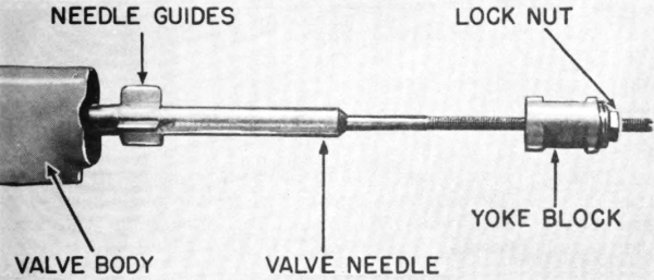
Fig 50. Valve needle, yoke block, and lock nut ready for
installation in fuel-valve body.
(3) Unscrew diaphragm cap and pull out washer, support, and
valve-diaphragm assembly. To prevent loss of valve-needle adjustment80
(Fig 54), do not disturb position of yoke block by turning the needle.
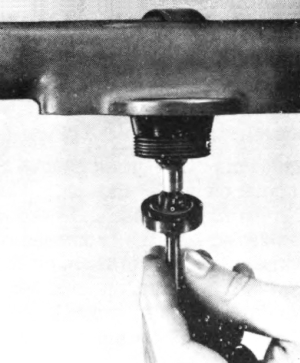
Fig 51. Placing diaphragm assembly in position in
fuel-valve body.
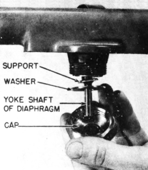
Fig 52. Installing parts in fuel-valve body.
(4) Slide the valve needle out of barrel; the yoke block and the lock
nut may then be unscrewed from the valve needle, but adjustment (see
d below) will be necessary when reinstalling.
c. Installation of barrel and valve-body assembly.
(1) To install valve needle, screw the yoke block and lock nut on the
needle (Fig 50). Insert needle in valve body and barrel.
(2) Insert valve-diaphragm assembly into valve body (Fig 51), making
sure that the yoke slips into the flat notches of yoke block.
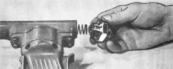
Fig 53. Installing spring retainer in fuel-valve body.
(3) Slip the diaphragm support, washer, and cap over the yoke81 shaft.
(Fig 52) Screw on the diaphragm cap by hand. Do not use a wrench.
Install valve grip. (Par 74 c)
(4) Place valve spring over end of needle and install spring retainer.
(Fig 53) Apply wrench very lightly to tighten spring retainer.
(5) Adjust needle (see d below), and screw plug into the spring
retainer.
(6) If hose has been removed, apply anti-seize compound lightly to the
threads. Screw hose into fuel-valve body. Wrench should be applied very
lightly to tighten.
d. Adjustment of valve needle. Needle is adjusted after installation
of parts in barrel and valve assembly. Use care when resetting needle,
as smooth operation of the weapon depends on accurate adjustment.
(1) Remove ignition shield (Par 18) and plug from gun.
(2) Use the valve-adjusting wrench (Fig 8) to hold the lock nut and
apply a cabinet (narrow-bladed) screw driver (Fig 8) in the end of the
needle. Turn needle until it makes a snug fit in the nozzle opening.
(3) Compress the valve lever and grip safety. The needle should draw
back into the nozzle with the tip of the needle at the smallest
diameter opening in the nozzle. (Fig 54)
(4) When the needle has been correctly adjusted, as in (3) above,
tighten the lock nut with the valve-adjusting wrench, keeping the
needle from turning with the screw driver. This will lock the
adjustment. Screw plug into the spring retainer.
(5) Replace ignition shield. (Par 18)
e. Maintenance of barrel and valve body.
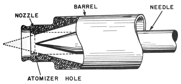
Fig 54. Valve-needle adjustment. Solid lines show needle
in correct open position with point at smallest diameter of nozzle.
Broken lines show needle in closed position.
(1) Damaged parts. Replace worn or damaged parts. If the diaphragm
shows evidence82 of tears or separation, or if leaks occur at the
diaphragm, replace the valve-diaphragm assembly.
(2) Valve spring. If valve spring has lost resiliency, grasp it by
the ends and stretch slightly, or replace.
(3) Nozzle leaks. If valve leaks at nozzle, and cleaning
(Par 55 d) does not remedy the leak, adjust needle (see d above). If leak
persists, either replace barrel and needle, or lap seat. To lap, place
lapping compound on seat (in nozzle) and on needle point. Turn needle
in seat until parts make a tight connection when seated. Remove lapping
compound, reassemble, adjust needle, and test fire.
(4) Atomizer hole. If atomizer hole is clogged, clean with fine wire.
(Par 52 i)
76. IGNITION HEAD.
a. Description and functioning. (Fig 55) The ignition head ignites
the fuel when the flame thrower is fired. It is mounted on the fore
part of the barrel. It consists of:
(1) Ignition-head body, which includes half of the front grip. Three
set screws serve to tighten the ignition-head body to the barrel. The
ignition-head body is made of aluminum.
(2) Trigger and trigger bearing, held between the ignition-head body
and the coverplate by the trigger screw.
(3) Trigger rod, one end of which is held in the trigger bearing,
the other extending through the ignition-head body. Pulling the
trigger shoves the trigger rod forward, causing it to push a match in
the ignition cylinder. The match ignites an incendiary charge in the
ignition cylinder.
(4) Trigger spring, which hooks over a projection of the trigger and
is held at its lower end by a screw, which is held in the ignition-head
body. This spring pulls the trigger rod back from the firing position
after the firer releases the trigger.
(5) Latch, located in the ignition-head body, in front of and above
the trigger guard. The latch, set on a pin, engages the notch of the
ignition shield, locking it in place. A latch spring holds latch in
position.
(6) Coverplate, an aluminum casting which constitutes the left
section of the front grip and covers the working parts seated in the
ignition head body. The coverplate and body are held together by four
screws and four lock washers.
(7) Spring case, which turns the ignition cylinder when the trigger
is pulled.
(a) Four projections on the inner spring case are bent over the outer
spring case to hold the two parts together.
(b) The inner-case pin (Fig 56) engages a stop on the inside of the
ignition cylinder. The five projecting metal matches on the inside
of the ignition cylinder are each in turn stopped by the lug on the
forward-facing surface of the ignition-head body.
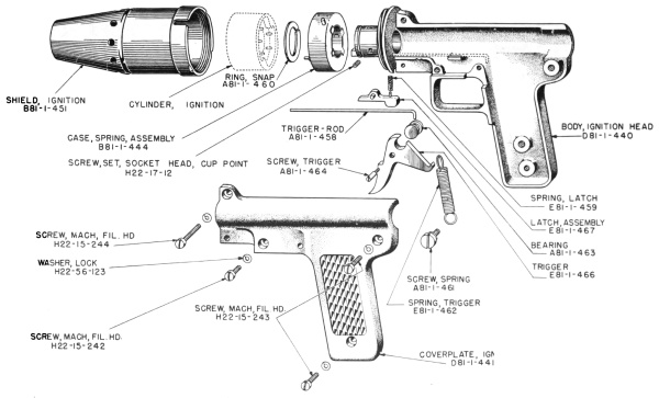
Fig 55. Ignition head disassembled, showing nomenclature
and Chemical Warfare Service stock numbers for requisitioning spare
parts.
84When the trigger is pulled, the trigger rod pushes a match
forward, causing an incendiary charge in the ignition cylinder to
ignite. The spring in the case rotates the ignition cylinder until
another match is stopped by the lug.
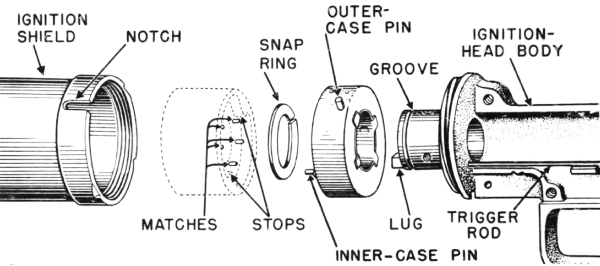
Fig 56. Parts of ignition head and ignition cylinder.
(c) The outer-case pin (on the outside surface of the outer spring
case) fits into the notch in the ignition shield and holds the spring
case as the shield is screwed into position. This action winds the
spring in the case.
(d) A snap ring holds the spring case on the ignition-head body.
(8) Ignition shield, a cylindrical, thin-metal tube with a conical
front end. The shield guides the flame and protects the firer. Eight
holes around the base of the cone provide an air intake for burning
the fuel. The base of the shield is threaded, and it screws onto the
ignition-head body. A notch (Fig 56) in the base of the shield receives
the latch and the outer-case pin of the spring case.
b. Removal of ignition head. To remove the ignition head, proceed as
follows:
(1) Remove shield by lifting latch and unscrewing shield
counterclockwise. (Fig 14) Keep hands and face away from front of
barrel.
(2) If ignition cylinder has not been removed, remove it or allow it to
fall off barrel.
(3) Pry off snap ring which holds spring case in position, using screw
driver. (Fig 57) Be careful not to damage or break the ignition-head
body by applying too much leverage.
(4) Remove the four screws and lock washers which hold ignition-head
body and coverplate together. Lift off coverplate.
(5) Trigger, trigger spring, trigger rod, latch, and latch spring may
be removed.
(6) Using a hex wrench, loosen set screws (Fig 58) and withdraw barrel
from ignition head.
c. Installation of ignition head. To install ignition head, proceed
as follows:
(1) Insert barrel in ignition-head body, pushing it as far forward as
the shoulder on the barrel permits.
(2) Aline front grip and valve grip.
(3) Using hex wrench, tighten set screws on barrel enough to hold but
not so tight that barrel is dented.
(4) Place latch, latch spring, trigger and bearing, trigger rod, and
trigger spring in position.
(5) Put coverplate on ignition-head body and replace the four lock
washers and screws.
(6) Slip spring case over barrel, and lock by forcing snap ring into
the groove.
(7) When weapon is to be used on a mission, fit ignition cylinder
and ignition shield in place on nozzle end of barrel as described in
Paragraph 18.
d. Maintenance of ignition head.
(1) Servicing. The ignition head should be cleaned and lubricated
each time it is disassembled. (Par 49)
(2) Spring-case assembly. If outer case rotates and inner case does
not, and no spring action occurs, spring is broken and spring case
should be replaced as a unit. Do not disassemble or repair this part.
(3) Trigger rod and lug. When trigger is pulled all the way, end
of trigger rod should extend 1/16 inch beyond lug on forward-facing
surface of ignition-head body. If end of trigger rod is worn, replace
rod. Lug on the ignition-head body should be approximately 7/32 inch
high. If lug is worn or broken, replace ignition head body.
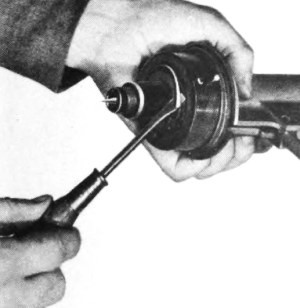
Fig 57. Prying snap ring from ignition head to remove
spring case.
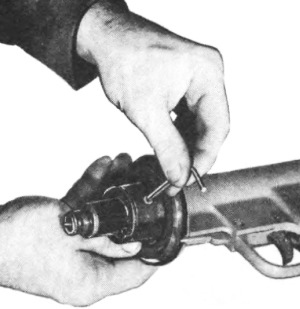
Fig 58. Loosening set screws with wrench so ignition
head may be lifted off barrel.
APPENDIX
Section XVIII SHIPMENT
AND STORAGE
77. SHIPMENT AND STORAGE.
The flame thrower is shipped and stored in a wooden packing case (Fig 59),
which measures approximately 34 inches by 23 inches by 19 inches.
Cubage of the case is approximately 8-1/2 cubic feet.
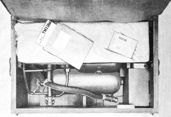
Fig 59. Opened packing chest showing flame thrower and
other contents as received.
a. Storage procedure. After use and servicing (Pars 55 and 56), if
the weapon is not to be promptly reused on another mission, it should
be returned to the packing case. Before disconnecting the gun group
from the tank group and storing the weapon, the ignition cylinder
should be removed, the fuel discharged, and the pressure released.
Operate fuel valve to release any residual pressure in the fuel tanks.
The deflector tube must be removed from the safety head (Fig 11) to
permit the tank group to fit into the chest. The deflector tube should
be kept in the spare parts87 kit or tool kit until the next use of the
weapon. The spare parts kit, the tool kit, the extra cans of cylinders,
TM 3-376A, and the coupling plug (Fig 7) should remain in the chest
except when they are being used. Wooden fittings hold the tank group in
place, with the pressure tank up. The gun group is disconnected from
the tank group and is kept with fuel hose connected to the gun on the
gun mounting board in the chest. (Fig 10)
b. Rust prevention. If the flame thrower, parts, and tools are to be
stored for a considerable length of time, especially in a damp climate,
all exposed metal surfaces should be covered with a rust-preventive
compound. Store in a dry place.
Section XIX LIST OF REFERENCES
78. REFERENCES.
References pertaining to the care and use of flame throwers include:
| AR 850-20 | Precautions in Handling Gasoline |
| AR 850-60 | Compressed Gas Cylinders; Safe Handling, |
| FM 31-50 | Attack on a Fortified Position and Combat in |
| FM 100-5 | Operations |
| TM 3-220 | Decontamination |
| TM 9-850 | Cleaning, Preserving, Lubricating, and Welding |
INDEX
| Paragraphs | ||
|---|---|---|
| – A – | ||
| Adjustable-end wrench, | 10a, 48a | |
| Adjustment of fire, | 25, 26c | |
| After firing, | 30, 55, 56 | |
| After six missions, | 56 | |
| Aging of fuel, | 35j | |
| Aiming, | 25, 26c, 34 | |
| Air compressor, | 32a, 32b, 39a | |
| Alcohol, | 35a | |
| Angles of tanks when firing, | 24b | |
| Anti-seize compound | ||
| source of, | 48b | |
| use of, | 58b, 70c, 73c | |
| Assistants, | 4f, 15 | |
| Atomizer hole | ||
| cleaning, | 52i | |
| description, | 75a | |
| – B – | ||
| Barrel | ||
| adjustment, | 52e, 75d | |
| cleaning, | 55d, 55i | |
| damage to, | 62, 75e | |
| description, | 75a | |
| maintenance, | 62, 75e | |
| Barrel and valve-body assembly, | 75 | |
| Bleeders, | 32c | |
| Burning time of fuels, | 34 | |
| Bursts, | 4b, 9b, 25c, 28, 29 | |
| Bushing, pipe, 3/4 inch by 1/2 inch, | 8, 10b, 48b | |
| – C – | ||
| Cap, diaphragm, | 75 | |
| Capacity, fuel, | 9e, 68a | |
| Carrier | ||
| adjustment, | 19, 56e, 60, 71 | |
| description, | 5a, 71a | |
| installation, | 71c | |
| maintenance, | 71e | |
| preventive maintenance, | 51, 55h | |
| removal, | 71b89 | |
| Carrier frame, | 71 | |
| Carrier pack, | 71 | |
| Carrying the flame thrower, | 19, 20, 55b, 56e, 60, 71 | |
| Catalog, | 48b | |
| Charging of pressure tank, | 4g, 32, 33, 61c, 66a | |
| Check valve | ||
| description, | 66a | |
| installation, | 66b | |
| operation, | 31, 32, 53d | |
| removal, | 66b | |
| replacement, | 66e | |
| Cleaning | ||
| gun, | 49a, 55, 56f, 58c, 74d, 75e, 76d | |
| tank group, | 55, 58c, 68c, 71e | |
| Cold weather, | 34-36, 44, 49, 64 | |
| Compound, anti-seize | ||
| source of, | 48b | |
| use of, | 58b, 70c, 73c | |
| Compound, pipe thread (anti-seize), | 48b, 58b, 70c, 73c | |
| Compressed air | ||
| charging apparatus, | 32, 33, 46, 48b | |
| leaks, | 56b, 61c | |
| release of, | 66b | |
| volume required, | 9g, 32c | |
| Compressor, air, | 32a, 32b | |
| Controls, | 14, 21, 26, 61, 74, 76 | |
| Cord | ||
| description, | 71a | |
| installation, | 71c | |
| replacement, | 48b, 60, 71e | |
| tightening, | 51h, 60, 71d | |
| Cotter pins, | 71 | |
| Coupling plug, | 10f, 17, 39c, 48b, 70 | |
| Coupling washer, | 10b, 48b, 58f, 70, 73d | |
| Coverplate, | 76 | |
| Cubage, | 9d | |
| Crankcase drainings, | 36 | |
| Cylinders | ||
| destruction, | 46 | |
| number required, | 9g, 32b | |
| use of, in charging, | 32, 33 | |
| use of, in filling, | 39 | |
| – D –90 | ||
| Dampness | ||
| effect on fuel, | 35e | |
| effect on ignition cylinder, | 31, 41 | |
| effect on thickener, | 35e | |
| effect on weapon, | 41, 51g, 71e, 77b | |
| Deflector tube, | 12j, 69, 77a | |
| Description of flame thrower, | 5, 65-76 | |
| Destruction | ||
| accessories, | 46b, d | |
| flame thrower, | 46a | |
| fuel, | 46c | |
| ignition cylinders, | 30a, 46f | |
| thickener, | 46e | |
| Diaphragm, | 75 | |
| Diaphragm cap, | 75 | |
| Diaphragm support, | 75 | |
| Diaphragm, valve, assembly, | 10b, 48b, 56e, 58a, 74, 75 | |
| Diaphragm washer, | 75 | |
| Diesel oil, | 35, 36, 40 | |
| Differences in models, | 7 | |
| Diffusion-pipe assembly, | 67, 68 | |
| Dimensions, | 9d | |
| Discharge time, | 9b | |
| Dome-type regulator, | 67d | |
| Drums, | 35-40 | |
| Duration of fire, | 9b, 34 | |
| Dust | ||
| blowing out, | 33j | |
| effect on operation, | 42 | |
| – E – | ||
| E1 ignition cylinders, | 18a, 31 | |
| E3 portable flame thrower, | 7a | |
| Engineers’ wrenches, | 10a, 48a | |
| – F – | ||
| Filling fuel tanks | ||
| by blowing, | 39 | |
| by force pump, | 38 | |
| by pouring, | 37 | |
| service when filling, | 53 | |
| Filling plug, | 37, 39, 49, 51d, 56b, 69 | |
| Filling with fuel, | 4g, 34-4091 | |
| Fire precautions, | 15c, 40, 55 | |
| Firers, | 4f, 15 | |
| Firing technique, | 26-30, 54, 56b | |
| Flexible shaft, | valve | |
| adjustment, | 66d | |
| description, | 66a | |
| installation, | 66c | |
| lubrication, | 49 | |
| removal, | 66b | |
| Frame clamp, | 68a, 71 | |
| Fuel | ||
| capacity, | 9e, 68a | |
| characteristics, | 34 | |
| destruction, | 46c | |
| left in tanks, | 24b | |
| per 100 fillings, | 9g | |
| precautions, | 35-40, 41 | |
| preparation, | 35, 40 | |
| ranges, | 22 | |
| weight, | 9c | |
| Fuel-filling hose, | 39 | |
| Fuel-filling line, | 39, 46b | |
| Fuel hose | ||
| description, | 70a | |
| installation, | 70c, 73c, 75 | |
| length, | 9d | |
| maintenance, | 40j, 52, 73d | |
| removal, | 40j, 70b, 73b, 75 | |
| replacement, | 5b, 48b, 58, 70, 73 | |
| stiffening of, | 21 | |
| Fuel oils, | 35, 36, 40 | |
| Fuel tanks | ||
| angle when firing, | 24b | |
| cleaning, | 53a, 53b | |
| description, | 5a, 68a | |
| fuel level, | 53b, 68a | |
| inspection, | 53a | |
| installation, | 68b | |
| maintenance, | 68c | |
| removal, | 68b | |
| Fuel valve | ||
| adjustment, | 61a | |
| cleaning, | 56f, 61d | |
| description, | 5b, 74a, 75a92 | |
| effects of dirt, | 42 | |
| failure to close, | 62 | |
| installation, | 61a, 74c, 75c | |
| leaks, | 56, 58 | |
| lubrication, | 49 | |
| operation, | 14c, 26b, 61a, 74a, 75a | |
| removal, | 74b, 75b | |
| testing, | 56c | |
| Funnel, | 35-37 | |
| – G – | ||
| Gage, fuel-tank testing, | 48b, 56b, 67d | |
| Gage, pressure testing, | 48b, 53d, 56b, 67d | |
| Gasoline, in fuels, | 34-40, 43, 44 | |
| Gloves, | 21g | |
| Grease, | 49 | |
| Grip safety, | 14c, 49, 56d, 62, 74 | |
| Grip support, | 74 | |
| Gun | ||
| assembling, | 74-76 | |
| carrying, | 25 | |
| cleaning, | 55d, 55i, 56f, 74d, 75e, 76d | |
| description, | 5b, 14, 72, 74-76 | |
| disassembling, | 74-76 | |
| length, | 9d | |
| lubrication, | 49 | |
| mounting board, | 10e | |
| preventive maintenance, | 50, 52, 54-56 | |
| requisitioning, | 5b | |
| storage, | 12g | |
| Gun group | ||
| assembling, | 72-76 | |
| connecting to tank group, | 17, 70, 73 | |
| description, | 5b, 14, 72-76 | |
| disassembly, | 72-76 | |
| lubrication, | 49 | |
| maintenance, | 72-76 | |
| preventive maintenance, | 50, 52, 54-56 | |
| storage, | 12g | |
| weight, | 9c | |
| – H –93 | ||
| Heat, effect on fuel, | 34-36, 40, 43 | |
| Hex wrenches, | 10a, 48a, 67d, 76b, 76c | |
| Hose connector, | 68a | |
| Hose, | fuel | |
| description, | 73a | |
| installation, | 70c, 73c, 75 | |
| length, | 9d | |
| maintenance, | 40j, 73d | |
| removal, | 40j, 70c, 73b, 75 | |
| replacement, | 5b, 48b, 58, 70, 73 | |
| stiffening of, | 21 | |
| – I – | ||
| Identification, | 6 | |
| Ignition action, | 14b, 44, 76a | |
| Ignition cylinders | ||
| action, | 14b, 31, 76a | |
| description, | 31, 76a | |
| destruction, | 30a, 46f | |
| discarding, | 30a | |
| duration of fire, | 9b | |
| failure, | 54a, 63, 64 | |
| loading of gun, | 18, 76a | |
| packing, | 10c, 31 | |
| precautions, | 18, 20, 31 | |
| storing, | 31, 41 | |
| use in training, | 15b, 18a, 30a | |
| Ignition failure, | 18, 26, 31, 44, 54a, 63, 64, 76d | |
| Ignition head | ||
| assembling, | 76c | |
| cleaning, | 49, 52, 54a, 76d | |
| description, | 5b, 76a | |
| disassembling, | 18, 76b | |
| effects of dirt, | 42, 52 | |
| failure, | 54a, 63, 64, 76d | |
| installation, | 76c | |
| loading, | 18, 76a | |
| lubrication, | 49, 76d | |
| maintenance, | 76d | |
| removal, | 76b | |
| Ignition-head body, | 76 | |
| Ignition shield, | 18, 52d, 54a, 55d, 76 | |
| Immersion, effects of, | 41 | |
| Incendiary effects, | 3, 34, 4494 | |
| Interchanging with E3, | 7a | |
| Interchanging with M1 or M1A1, | 7b, 8 | |
| – J – | ||
| Jungle ranges, | 22 | |
| – K – | ||
| Kerosene, | 35a, 36a, 40 | |
| Kit | ||
| tool, | 10, 77a | |
| spare parts, | 10, 77a | |
| service, | 48 | |
| – L – | ||
| Lapping needle and nozzle, | 75e | |
| Latch, | 76 | |
| Leaded gasoline, | 40n | |
| Leaks | ||
| fuel, | 56, 58, 66b, 68-70, 73-75 | |
| pressure, | 21, 51b, 53d, 56b, 61c, 66b | |
| Left valve grip, | 74 | |
| Line, fuel-filling, | 39 | |
| Lines, charging and filling | ||
| destruction, | 46 | |
| source, | 48b | |
| use, | 32, 33 | |
| Liquid fuels | ||
| aiming, | 25 | |
| characteristics, | 34 | |
| filling, | 37, 38 | |
| precautions, | 36-40 | |
| preparation, | 35, 40 | |
| ranges, | 22, 34 | |
| Loading ignition cylinder, | 18, 76a | |
| Lubrication, | 49 | |
| – M – | ||
| Marking, | 6, 18a | |
| M1 and M1A1 portable flame throwers, | 7b, 8 | |
| Moisture | 95 | |
| effect on fuel, | 35e | |
| effect on ignition cylinder, | 31, 41 | |
| effect on thickener, | 35e | |
| effect on weapon, | 41, 51g, 71e, 77b | |
| Mounting board, | 12g | |
| – N – | ||
| Needle | ||
| adjustment, | 52e, 75d | |
| cleaning, | 52, 55d | |
| description, | 75a | |
| installation, | 75c | |
| leaks, | 58 | |
| removal, | 75b | |
| Nitrogen | ||
| charging apparatus, | 32, 33, 46, 48b | |
| leaks, | 56b, 61c | |
| release of, | 66b | |
| volume required, | 9g, 32c | |
| Nozzle | ||
| adjustment, | 52e, 56b, 75d | |
| cleaning, | 52, 55d | |
| description, | 75a | |
| leaks, | 56b, 58, 75e | |
| – O – | ||
| Oxygen, hazard from use, | 32c | |
| – P – | ||
| Packing chest | ||
| cubage, | 9d | |
| dimensions, | 9d | |
| opening, | 12 | |
| use of, | 12, 30 | |
| weight, | 9c | |
| Paddle, | 35, 36 | |
| Painting, | 13, 41, 68c | |
| Pins, | (carrier) 71 | |
| Plug, coupling, | 10f, 17, 39c, 48b, 70 | |
| Plug, filling, | 37, 39, 49, 51d, 56b, 6996 | |
| Plug-retainer assembly, | 69 | |
| Plug, safety-head, | 37, 39, 49, 51d, 69 | |
| Plug, testing, | 56b, 67d | |
| Point-blank range, | 22 | |
| Positions, firing, | 24 | |
| Precautions | ||
| in training, | 15 | |
| when charging, | 33 | |
| when filling with fuel, | 37-40 | |
| when firing, | 22a, 24d | |
| when preparing fuel, | 35, 36, 40 | |
| when servicing, | 57 | |
| with cylinder, | 18, 31, 57 | |
| with gun, | 20 | |
| Pressure | ||
| charging, | 32, 33 | |
| charging apparatus, | 32, 33, 46, 48b | |
| lack of, | 56b, 61 | |
| leaks, | 56b, 61c | |
| pounds of, | 9f, 32, 56b | |
| release of, | 66b | |
| testing for, | 53d, 56b | |
| Pressure regulator | ||
| adjustment, | 56b, 59, 67d | |
| description, | 5a, 67a | |
| effects of dirt, | 42 | |
| installation, | 66c, 67c | |
| removal, | 67b | |
| replacement, | 48b, 56b, 59, 67 | |
| testing, | 56b, 61b, 67d | |
| Pressure tank | ||
| charging, | 32, 33 | |
| description, | 5a, 66a | |
| installation, | 66c | |
| removal, | 66b | |
| replacement, | 4g, 48b | |
| Pressure tank and valve assembly | ||
| adjustment, | 66d | |
| description, | 5a, 66a | |
| installation, | 66c | |
| maintenance, | 66e | |
| removal, | 66b | |
| testing for leaks, | 53d | |
| Pressure-tank clamp | 97 | |
| description, | 66a | |
| installation, | 66c | |
| removal, | 66b | |
| repair, | 51e | |
| Pressure-tank valve | ||
| description, | 5a, 66a | |
| effects of dirt, | 42 | |
| installation, | 66c | |
| operation, | 14a, 21, 55g, 61b | |
| removal, | 66b | |
| replacement, | 48b, 66e | |
| testing, | 51a, 53c | |
| Pressure-tank valve handle, | 14a, 21, 48b, 66 | |
| Preventive maintenance services, | 50-56 | |
| Pump | ||
| force, | 38 | |
| air, | 39a | |
| – R – | ||
| Rain, effect on firing, | 41, 77b | |
| Ranges, | 4c, 15b, 15c, 22, 61, 67d | |
| Recoil, | 24c | |
| Records, | 2, 49a | |
| References, | 1b, 78 | |
| Regulator tube, | 66, 67 | |
| Removal of tank group, | 55b, 66-71 | |
| Right valve grip, | 74 | |
| Rocker arm, | 49, 74, 75a | |
| – S – | ||
| Safety, grip, | 14c, 62, 74 | |
| Safety-head plug, | 37, 39, 51d, 69 | |
| Safety head, replacement, | 51d, 54b, 55f, 56b, 59, 69 | |
| Screening effect, | 3, 34 | |
| Screw drivers, | 10a, 48a, 52f, 74c, 75d, 76b | |
| Seine cord | ||
| description, | 71a | |
| installation, | 71c | |
| replacement, | 48b, 60, 71e | |
| tightening, | 51h, 60, 71d | |
| Service kit, | 48 | |
| Service, on receipt of equipment, | 12, 1398 | |
| Set-screw wrenches, | 10a, 48a, 67d, 76b, 76c | |
| Shield, ignition, | 18, 52d, 54a, 55d, 76 | |
| Shipment, | 77 | |
| Short range, causes of, | 61 | |
| Sighting, | 25 | |
| Skids, use of, | 24 | |
| Smoke, | 3, 34 | |
| Smoking, | 15, 40d | |
| Snap ring, | 76 | |
| Soaking the target, | 29 | |
| Spare parts in service kit, | 48, 77a | |
| Spare parts kit, | 10b | |
| Spray of fuel, | 61a | |
| Spring case | ||
| cleaning, | 52j, 76d | |
| description, | 76 | |
| effects of dust, | 42, 52j | |
| general, | 10b, 18, 31, 76 | |
| lubrication at, | 49, 52j, 76d | |
| maintenance, | 76d | |
| replacement, | 48b, 63b, 76d | |
| Spring retainer and plug, | 52g, 75 | |
| Spring, trigger, | 63d, 76 | |
| Spring-type regulator, | 67d | |
| Spring, valve, | 75 | |
| Spring, valve-grip, | 74 | |
| Stem, pressure valve, | 66d | |
| Storage | ||
| charging lines, | 42 | |
| cylinders, | 33, 77a | |
| filling lines, | 42 | |
| flame thrower, | 12, 30f, 41, 42, 77 | |
| fuel, | 35j, 36i, 40 | |
| ignition cylinders, | 31 | |
| Straps, adjustment, | 19, 51i, 60b, 71d | |
| Sun, exposure of flame thrower to, | 40, 43 | |
| Support, diaphragm, | 75 | |
| – T – | ||
| Tactics, | 3, 4e | |
| Tank connector, | 68a | |
| Tank coupling | ||
| cleaning, | 70d | |
| description, | 70a99 | |
| installation, | 70c | |
| leaks, | 58, 70d | |
| maintenance, | 51c, 70c, 70d, 73d | |
| operation, | 17, 70, 73a | |
| removal, | 70b | |
| testing, | 51c | |
| Tank group | ||
| adjustment, | 66-71 | |
| carrying, | 19, 24, 55b, 71 | |
| connecting to gun, | 4g, 17, 70 | |
| description, | 5a, 65-71 | |
| dimensions, | 9d | |
| interchanging, | 4g, 17, 70 | |
| installation, | 66-71 | |
| maintenance, | 66-71 | |
| preventive maintenance, | 50, 51, 53-56 | |
| removal, | 55b, 66-71 | |
| requisitioning, | 5a | |
| weight, | 9c | |
| Targets, | 3, 25 | |
| Temperature, effects of, | 34-36, 40, 43, 44, 49, 64 | |
| Test firing, | 12k, 35k, 36h, 56b | |
| Thickened fuel | ||
| aiming, | 25c, 26c | |
| characteristics, | 34 | |
| filling, | 37-39 | |
| precautions, | 35, 39, 40 | |
| preparation, | 35, 40 | |
| ranges, | 22, 34 | |
| Thickener | ||
| destruction, | 46e | |
| quantity, | 9g, 35 | |
| storage, | 35 | |
| use, | 35 | |
| Time of discharge, | 9b | |
| Tool kit, | 10a, 77a | |
| Training, | 15, 30a | |
| Trigger, | 14b, 26a, 49, 52, 63, 76 | |
| Trigger rod | ||
| description, | 76a | |
| lubrication, | 49 | |
| maintenance, | 52l, 76d | |
| Trigger screw, | 76 | |
| Trigger spring, | 52k, 63d, 76100 | |
| – U – | ||
| Underbrush, | 22b | |
| Uses of flame throwers, | 3 | |
| – V – | ||
| Valve-adjusting wrench | ||
| source, | 48a | |
| use, | 75d | |
| Valve, pressure-tank, | 75 | |
| Valve-diaphragm assembly, | 10, 48b, 56c, 58a, 74, 75 | |
| Valve flexible shaft | ||
| adjustment, | 66d | |
| description, | 66a | |
| installation, | 66c | |
| lubrication, | 49 | |
| removal, | 66b | |
| Valve grip | ||
| action, | 14c, 74a | |
| description, | 74a | |
| effects of dirt, | 42 | |
| installation, | 74c | |
| leaks, | 58a | |
| lubrication, | 49, 56d, 74d | |
| maintenance, | 74d | |
| removal, | 74b | |
| Valve-grip spring, | 74 | |
| Valve lever | ||
| description, | 74a | |
| installation, | 74c | |
| lubrication, | 49 | |
| operation, | 14c, 62, 74a | |
| play, | 52e | |
| removal, | 74b | |
| Valve needle | ||
| adjustment, | 52e, 75d | |
| cleaning, | 52, 55d | |
| description, | 75a | |
| installation, | 75c | |
| leaks, | 58 | |
| removal, | 75b, 75e | |
| Valve, fuel | 101 | |
| adjustment, | 61a | |
| cleaning, | 56f, 61d | |
| description, | 5b, 74a, 75a | |
| effects of dirt, | 42 | |
| failure to close, | 62 | |
| installation, | 61a, 74c, 75c | |
| leaks, | 56c, 58 | |
| lubrication, | 49 | |
| operation, | 14c, 26b, 61a, 74a, 75a | |
| removal, | 74c, 75c | |
| testing, | 56c | |
| Valve pressure-tank | ||
| description, | 5a, 66a | |
| effects of dirt, | 42 | |
| installation, | 66c | |
| operation, | 14a, 21, 55g, 61b | |
| removal, | 66b | |
| replacement, | 48b, 66e | |
| testing, | 51a, 53c | |
| Valve spring, | 75 | |
| Void in fuel tanks, | 53b, 68a | |
| – W – | ||
| Washer, coupling, | 10b, 48b, 70, 73d | |
| Washer, diaphragm, | 75 | |
| Water | ||
| and ignition cylinder, | 31, 41 | |
| effect on fuel, | 35e | |
| effect on thickener, | 35e | |
| effect on weapon, | 41, 51g, 71e | |
| use in testing, | 56b, 67d | |
| use in training, | 15 | |
| Weights, | 4d, 9c | |
| Wind, effects of, | 23, 45 | |
| Wrenches, | 10a, 48a, 67d | |
| – Y – | ||
| Yoke, | 75 | |
| Yoke block, | 75 | |
| Yoke shaft, | 75 | |
NOTES
REPRODUCTION PLANT
CHEMICAL WARFARE SCHOOL
EDGEWOOD ARSENAL MD
1944
Transcriber’s Notes:
The original accentuation, spelling, punctuation and hyphenation has been retained, except for apparent typographical errors.