LABORATORY MANUAL
OF
GLASS-BLOWING
LABORATORY MANUAL
OF
GLASS-BLOWING
BY
FRANCIS C. FRARY, Ph. D.
ASSISTANT PROFESSOR OF CHEMISTRY
UNIVERSITY OF MINNESOTA
McGRAW-HILL BOOK COMPANY, Inc.
239 WEST 39TH STREET, NEW YORK
6 BOUVERIE STREET, LONDON, E. C.
1914
Copyright, 1914, by the
McGraw-Hill Book Company, Inc.
PREFACE
The purpose of this little book is to provide a clear and
detailed discussion of the elements of glass-blowing.
Many laboratories in this country, especially in the west,
are located a long way from any professional glass-blower,
and the time and money spent in shipping broken apparatus
several hundred miles to be mended could often
be saved if some of the laboratory force could seal on a
new stopcock, replace a broken tube, or make some
temporary repairs. Many men in physical or chemical
laboratories have occasion to modify some piece of apparatus
designed perhaps for other uses, or to design new
apparatus. To such also, the ability to perform some of
the operations herein described may be very valuable.
No originality is claimed for the methods here described.
They are those which the author has found
most suitable and convenient in his own work, and most
easily learned by students. The aim has been to describe
each operation in such detail that a beginner can follow
the process without help and, with practice, attain
satisfactory results. It is, however, much easier to perform
any of the operations described, after seeing some
one else perform it correctly; since the temperature, the
exact time to begin blowing the glass, and many other little
details are very difficult to obtain from a description.
It has not been thought worth while to describe the
process of making stopcocks, thermometers, vacuum
tubes, etc., as such things can be purchased more cheaply
and of much better quality than any amateur can make
unless he is willing to spend a very large amount of time
in practice. For similar reasons the manipulation of
quartz glass has been omitted.
The author will be grateful for all suggestions and criticisms
tending to improve the methods presented. If
some of them appear to be given in excessive detail, the
reader will remember that many things which are obvious
to the experienced worker are not so to the beginner, and
that it is the little details in the manipulation which
often spell success or failure in glass-blowing.
F. C. F.
Minneapolis, Minn.,
January, 1914.
CONTENTS
| Page | |
| Preface | v |
| CHAPTER I | |
| Materials and Apparatus | 1 |
| Varieties and defects of glass—Devitrification—Annealing | |
| glass—Blowpipe and bellows—Light—Arrangement | |
| of exercises. | |
| CHAPTER II | |
| General Operations | 7 |
| Cutting, bending, constricting and flanging the tubing—Methods | |
| of rotation and blowing. | |
| CHAPTER III | |
| Elementary Exercises | 16 |
| Joining two pieces of tubing of the same diameter—The | |
| “tee” tube—Joining two tubes of different diameters—Blowing | |
| bulbs. | |
| CHAPTER IV | |
| Advanced Exercises | 35 |
| Sealing a tube through another tube: The gas-washing | |
| tube, suction pump, and Kjeldahl trap. | |
| CHAPTER V | |
| Modified Methods and Special Operations | 43 |
| Capillary tubing—Glass rod—Mending stopcocks—Closed | |
| circuits of tubing—Spirals—Ground joints—Sealing | |
| in platinum wire—Sealing vacuum tubes—Closed | |
| tubes for heating under pressure. | |
| Index | 59 |
LABORATORY
MANUAL OF GLASS-BLOWING
CHAPTER I
Materials and Apparatus
One of the most important factors in the success of any
piece of glass-blowing is the glass employed. As is well
known, there are two general varieties of glass: Lead
glass and soda glass. Formerly much apparatus was
made of lead glass, but at present it is very seldom met
with, except in the little drops of special glass used to seal
platinum wires into the larger sizes of tubes. Lead glass
is softer and more readily fusible than soda glass, but has
the disagreeable property of growing black in a few
seconds unless worked in a strong oxidizing flame. This
may be prevented by using a “hissing” flame, with a large
excess of air, and working in the extreme end of the flame;
or the black lead formed may thus be reoxidized, and the
glass restored to its original clearness.
Almost all the soft glass on the market is a soda glass,
although sometimes part of the soda is replaced by
potash. Most of the hard glass appears to be a potash
glass. The following qualities are desirable in a glass for
ordinary working: (1) moderately low working temperature,
(2) freedom from air bubbles, striations and
irregularities, (3) proper composition, so that the glass
will not devitrify or crystallize while being handled at its
working temperature, (4) ability to withstand rapid
heating without cracking.
The working temperature of different samples of so[Pg 2]-called
“soft glass” varies a good deal, and is best determined
by trial. The glass should become almost soft
enough for blowing in a flame that still shows a little
yellow near the tip, so that at the highest temperature of
the flame it may flow fairly freely and thus easily eliminate
irregularities in thickness. If the glass is too hard,
the shrinking of the glass, collection of material for a
bulb, and in fact most of the working processes will be
slower, and the glass will not stay at its working temperature
long enough after its removal from the flame
to permit it to be properly blown.
Air bubbles in the original batch of glass are drawn out
into long hair-like tubes during the process of manufacture.
When such tubing is worked, the walls of these
microscopic tubes collapse in spots, and the air thus
enclosed will often collect as a small bubble in the wall,
thus weakening it. Irregularities are of various kinds.
Some of the larger sizes of thin-walled tubing often have
one half of their walls much thicker than the other, and
such tubing should only be used for the simplest work.
Some tubing has occasional knots or lumps of unfused
material. The rest of the tube is usually all right, but
often the defective part must be cut out. The presence
of striations running along the tube is generally an indication
of hard, inferior glass. Crookedness and non-uniformity
of diameter are troublesome only when long
pieces must be used.
Devitrification is one of the worst faults glass can
possibly have. It is especially common in old glass, and
in glass which has contained acids. It seems to be of two
sorts. One variety manifests itself on the surface of the
glass before it reaches its working temperature, but if
the glass be heated to the highest temperature of the
flame it will disappear except in the portion at the edge
of the heated part. The glass seems to work all right, but[Pg 3]
an ugly crystallized ring is left at the edge of the portion
heated. This kind appears most frequently in old glass
which was originally of good quality, but has in time been
superficially altered, probably by the loss of alkalies.
The other variety of devitrification does not appear
when the glass is first heated; but after it has been maintained
at or above its working temperature for a longer
or shorter time, it will be noticed that the outer surface
has lost its smoothness, and appears to be covered with
minute wrinkles. It will also be found that the glass has
become harder, so that it becomes impossible to work it
easily. Further heating only makes the matter worse,
as does the use of a higher temperature from the start.
In fact it will often be found that a piece of comparatively
soft glass which devitrifies almost at once in a
“hissing” flame can be worked without serious difficulty
if care be taken to use a flame still decidedly tinged with
yellow. Even good glass will begin to devitrify in this
way if heated too long at the highest temperature of the
flame, so care should always be taken (1) to reduce the
time of heating of any spot of glass to a minimum; i.e., get
the desired result at the first attempt, if possible, or at
least with the minimum of reheating and “doctoring,”
and (2) avoid keeping the glass at the highest temperature
of the flame any longer than necessary. This may be
accomplished by doing all heating, shrinking, etc., of the
glass in a flame more or less tinged with yellow, and only
raising the temperature to the highest point when ready
to blow the glass. This kind of devitrification is apparently
due to volatilization of the alkalies from the glass in
the flame, and it is said that it can be partly remedied or
prevented by holding a swab of cotton saturated with a
strong solution of common salt in the flame from time to
time as the glass is heated.
The toughness of glass, i.e., its ability to withstand[Pg 4]
variations of temperature, depends on its composition
and the care taken in its annealing. In general, large
pieces of glass should be heated very slowly in the smoky
flame, and the larger the diameter of the tube the greater
the length which must be kept warm to prevent cracking.
All large pieces should be carefully heated over their
whole circumference to the point where the soot deposit
burns off, before being finally cooled. After being thus
heated they are cooled in a large smoky flame until well
coated with soot, then the flame is gradually reduced in
size and the object finally cooled in the hot air above it
until it will not set fire to cotton. If thought necessary,
it may then be well wrapped in cotton and allowed to
cool in the air. If not properly annealed the place heated
may crack spontaneously when cold, and it is quite certain
to crack if it is reheated later.
Next in importance to the glass are the blow-pipe and
the bellows. Any good blast lamp, such as is ordinarily
used in a chemical laboratory for the ignition of precipitates,
will be satisfactory; provided it gives a smooth
regular flame of sufficient size for the work in hand,
and when turned down will give a sharp-pointed flame
with well-defined parts. Where gas is not available, an
ordinary gasoline blow-torch does very well for all operations
requiring a large flame, and a mouth blow-pipe
arranged to blow through a kerosene flame does well for
a small flame. Several dealers make blow-torches for
oil or alcohol which are arranged to give a small well-defined
flame, and they would doubtless be very satisfactory
for glass-work. Any good bellows will be
satisfactory if it does not leak and will give a steady
supply of air under sufficient pressure for the maximum
size of flame given by the lamp used. A bellows with a
leaky valve will give a pulsating flame which is very
annoying and makes good work very difficult. When[Pg 5]
compressed air is available it can be used, but if possible
it should be arranged so that the supply can be controlled
by the foot, as both hands are usually needed to hold the
work. For the same reason the supply of air is usually
regulated by varying the rate of operation of the bellows,
rather than by adjusting the valve of the blast-lamp.
On the other hand, it will be found best to always adjust
the flow of the gas by means of the cock on the lamp,
rather than that at the supply pipe. The operator must
have complete control over the flame, and be able to
change its size and character at short notice without
giving the work a chance to cool, and often without ceasing
to support it with both hands.
Glass-blowing should be done in a good light, but preferably
not in direct sunlight. The operator should be
seated in a chair or on a stool of such a height that when
working he may comfortably rest one or both elbows on
the table. The comfort of the operator has a decided
influence on the character of his work; especially in the
case of a beginner, who often defeats his purpose by
assuming uncomfortable and strained positions. Steadiness
and exact control of both hands are essential in most
operations; any uncomfortable or strained position tires
the muscles and weakens the control of the operator over
them.
In the arrangement of the exercises here presented,
several factors have been considered. It is important
that the first exercises be simple, although not necessarily
the simplest, and they should teach the fundamental
operations which will be used and amplified later. They
should in themselves be things which are of importance
and commonly used in glass-work, and they should be so
arranged that the fundamental points, such as the rotation
of glass, the proper temperature, blowing and shrinking
the glass may be learned with a minimum expenditure[Pg 6]
of time, glass and gas. It is therefore recommended that
the beginner take them up in the order given, at least as
far as No. 7, and that each be mastered before attempting
the next. The beginner should not leave the first exercise,
for example, until he can join together two pieces
of tubing so that they form one piece of substantially
uniform inner and outer diameter, and without thick or
thin spots. From two to four practice periods of two
hours each should suffice for this. This chapter and the
following one should also be frequently read over, as many
of the points discussed will not be understood at first and
many of the manipulations described will not be necessary
in the simpler exercises.
CHAPTER II
General Operations
Cutting the Glass.—For this purpose a “glass-knife”
is preferred to a file, if the glass is cold: if it is hot a file
must always be used, and its edge slightly moistened to
prevent drawing the temper. The glass-knife is simply
a flat piece of hard steel, with the edges ground sharp on
an emery wheel. The bevel of the edge should be from
30 to 60 degrees. An old flat file can easily be ground
into a suitable knife. The glass-knife makes a narrower
scratch than the file but appears more likely to start the
minute crack which is to cause the tube to break at that
point, and the break is more likely to give a good square
end. The scratch should be made by passing part of
the knife or file once across the glass, never by “sawing”
the tool back and forth. This latter procedure dulls the
tool very quickly.
In breaking a piece of glass tubing, many persons forget
that it is necessary to pull the ends apart, as well
as to bend the tube very slightly in such a direction as to
open up the minute crack started in the scratch. Care
in breaking the tube is essential, as it is impossible to do
as good work with uneven ends as with square ones.
When tubing of large diameter or thin wall is to be cut,
it is often better not to attempt to break it in the usual
way, but to heat a very small globule of glass (1⁄16 to 1⁄8
inch diameter) to red heat, and touch it to the scratch.
This will usually start the crack around the tube; if it
has not proceeded far enough, or has not gone in the de[Pg 8]sired
direction, it may be led along with a hot point of
glass. This is put a little beyond the end of the crack,
and as the latter grows out toward it, moved along the
path where the crack is desired. This point of glass is
also very useful in breaking off very short ends of tubes,
where there is not room to get a firm enough hold and
sufficient leverage to break the tube in the ordinary
way, and for breaking tubes attached to large or heavy
objects, which would be likely to make trouble if treated
in the ordinary way.
Another way of cutting large tubing, especially if it
has rather thick walls, is to make a scratch in the usual
way, and then turn on the smallest and sharpest possible
flame of the blast lamp. The tube is next taken in both
hands and held horizontally above the flame so that the
scratch is exactly over it. The tubing is now rotated
rapidly about its axis, and lowered so that the flame is
just tangent to its lower side. After about ten seconds
of heating, it is removed from the flame and the hot portion
quickly breathed upon, when it will generally crack
apart very nicely. Care must be taken to hold the tube
at right angles to the flame during the heating, and to
rotate it so that only a narrow strip of the circumference
is heated, and the scratch should be in the center of this
heated strip. By this means tubing as large as two inches
in diameter is readily broken.
Griffin’s glass cutter, which contains a hardened steel
wheel, like that on any ordinary window-glass cutter, and
a device by which this can be made to make a true cut
clear around the tube, is a very handy article, especially
for large tubing, and may be obtained from any dealers
in chemical apparatus.
Bending Glass.—Inasmuch as this is one of the commonest
operations in the laboratory, it is assumed that
the reader knows how to perform it. However, it[Pg 9]
should be noted that in order to obtain the best results
a broad (fish-tail burner) flame should generally be used,
and the tube rotated on its axis during the heating, and
allowed to bend mostly by its own weight. If large tubing
is to be bent, one end must be stoppered and great
care used. Whenever the tube shows signs of collapsing
or becoming deformed, it must be gently blown out into
shape, heating the desired spot locally if necessary. A
blast-lamp is likely to be more useful here than the fish-tail
burner.
Drawing Out a Tube.—Most students learn this the
first day of their laboratory work in chemistry, but few
take pains to do it well. The tube should be heated in
the flame of a Bunsen burner, or blast lamp (preferably
the latter) until it is very soft. During this time it must
be continuously rotated about its axis, and so held that
the edges of the heated zone are sharply defined; i.e.,
it should not be allowed to move back and forth along
its own axis. When so hot that it cannot longer be held
in shape, the tube is removed from the flame, and the
ends slowly and regularly drawn apart, continuing the
rotation of the tube about its axis. By regulating the rate
of drawing and the length of tube heated, the desired
length and diameter of capillary may be obtained. The
tube should always be rotated and kept in a straight line
until the glass has set, so that the capillary may have the
same axis as the main tube. This capillary or “tail”
is often a very necessary handle in glass-blowing, and if
it is not straight and true, will continually make trouble.
In drawing out very large tubing, say from one to
two inches in diameter, it is often necessary to draw the
tube in the flame, proceeding very slowly and at a
lower temperature than would be used with small tubing.
This is partly on account of the difficulty of heating
large tubing uniformly to a high temperature, and[Pg 10]
partly in order to prevent making the conical part of
the tube too thin for subsequent operations.
Constricting a Tube.—Where a constriction is to be
made in a tube, the above method must be modified, as
the strength of the tube must be maintained, and the
constricted portion is usually short. Small tubes are
often constricted without materially changing their outside
diameter, by a process of thickening the walls. The
tube is heated before the blast lamp, rotating it about
its axis as later described, and as
it softens is gradually pushed
together so as to thicken the walls
at the heated point, as in a, Fig. 1.
When this operation has proceeded
far enough, the tube is removed
from the flame, and the ends cautiously
and gently drawn apart,
continuing the rotation of the tube
about its axis and taking care not
to draw too rapidly at first. The
resulting tube should have a uniform exterior diameter,
as shown in b, Fig. 1.
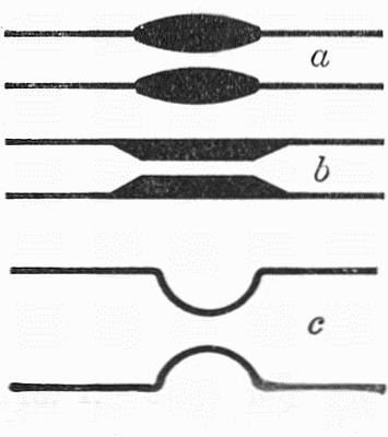
Fig. 1.—Constricting a
tube.
This method of constriction is not suited to tubes
much over 1⁄4 inch in diameter, since the mass of glass
in the constricted part becomes so thick as to be difficult
to handle when hot, and likely to crack on cooling.
Larger tubes are therefore constricted by heating in a
narrow flame, with constant rotation, and when soft,
alternately gently pulling the ends apart and pushing
them together, each motion being so regulated that the
diameter of a short section of the tube is gradually reduced,
while the thickness of the wall of the reduced
portion remains the same as that of the rest of the tube,
or increases only slightly. This pulling and pushing of
the glass takes place in the flame, while the rotation is[Pg 11]
being continued regularly. The result may appear as
indicated in c, Fig. 1. The strength of the work depends
upon the thickness of the walls of the constricted portion,
which should never be less than that in the main tube,
and usually a little greater. This operation is most
successful with tubing having a relatively thin wall.
Flanging a Tube.—This operation produces the characteristic
flange seen on test-tubes, necks of flasks, etc.,
the object being twofold: to finish the end neatly and to
strengthen it so that a cork may be inserted without
breaking it. This flanging may be done in several ways.
In any case the first operation is to cut the tube to a
square end, and then heat this end so that the extreme
sixteenth or eighth of an inch of it is soft and begins to
shrink. The tube is of course rotated during this heating,
which should take place in a flame of slightly greater
diameter than the tube, if possible. The flange is now
produced by expanding this softened part with some
suitable tool. A cone of charcoal has been recommended
for this purpose, and works fairly well, if made so its
height is about equal to the diameter of its base. The
tube is rotated and the cone, held in the other hand, is
pressed into the open end until the flange is formed. A
pyramid with eight or ten sides would probably be better
than the cone.
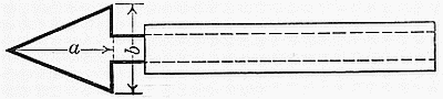
Fig. 2.—Flanging tool.
A better flanging tool is made from a triangular piece
of copper or brass, about 1⁄16 inch thick, and mounted
in a suitable handle. Such a tool is shown in Fig. 2,
being cut from a sheet of copper and provided with a[Pg 12]
handle made by wrapping asbestos paper moistened with
sodium silicate solution about the shank of the tool.
It is well to have several sizes and shapes of these tools,
for different sizes of tubing. The two sizes most used
will be those having about the following dimensions:
(1) a = 2 inches, b = 1 inch; (2) a = 1 inch, b = 1 inch.
When the end of the tube is softened, the tool is inserted
at an angle, as indicated in Fig. 3, and pressed against
the soft part, while the tube is quickly rotated about its
axis. If the flange is insufficient the operation may be
repeated. The tool should always be warmed in the
flame before use, and occasionally greased by touching
it to a piece of wax or paraffin. After the flange is complete,
the end must be heated again to the softening temperature
and cooled slowly, to prevent it from cracking.
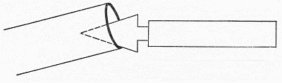
Fig. 3.—Flanging a tube with flanging tool.
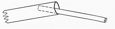
Fig. 4.—Flanging a tube with carbon rod or wire.
Some glass-blowers use a small carbon rod, about
3⁄16 inch in diameter, as a flanging tool for tubes larger
than about 3⁄8 inch diameter, and a small iron wire or
similar piece of metal for smaller tubes. In this case the
tube is heated as above described, and the rod or wire
inserted in the end at an angle and pressed against the
softened part, as indicated in Fig. 4, while the tube is[Pg 13]
rotated about its axis. For large heavy tubes a larger
carbon would be used.
Rotation of the Tube.—This is the fundamental manipulation
in glass-blowing, and upon it more than all
else depends the uniformity and finish of the work, and
often the possibility of accomplishing the work at all.
Directions for it will be given on the assumption that
the reader is right-handed; if otherwise, the position of
the hands is of course reversed. The object of rotation
is to insure even heating of the whole circumference of
the tube at the point of attack, to equalize the effect of
gravity on the hot glass and prevent it from falling out of
shape when soft, and to keep the parts of the tube on
each side of the heated portion in the same straight line.
In rotating the tube, both hands must be used, so that
the two ends may revolve at the same rate and the glass
in the hot part not be twisted. The rotation is performed
by the thumb and first finger of each hand, the other
fingers serving to support the tube. As it is almost
always necessary to follow rotating and heating a tube by
blowing it, the hands should be so placed that it will be
easy to bring the right-hand end up to the mouth without
shifting the hold on the glass. For this reason the left
hand grasps the glass with the palm down, and the right
hand with the palm turned toward the left. If there is
any choice, the longer and heavier part of the tube is
usually given to the left hand, and it is planned to blow
into the shorter end. This is because it is easier to
support the tube with the hand which has the palm
down. This support is accomplished by bending the
hand at the wrist so that it points slightly downward, and
then curling the second, third and little fingers in under
the tube, which is held between them and the palm.
This support should be loose enough so that the thumb
and first finger can easily cause the tube to rotate regu[Pg 14]larly
on its axis, but firm enough to carry all the weight
of the tube, leaving the thumb and first finger nothing
to do but rotate it. The hand must be so turned, and
the other fingers so bent, that the thumb and first finger
stretch out nearly to their full length to grasp the tube
comfortably.
The right hand is held with the palm toward the left,
the fingers except the first slightly bent, and the tube
held between the first finger and the thumb while it
rests on the second finger and that portion of the hand
between the base of the first finger and the thumb.
Rotation of the tube is accomplished by rolling it between
the thumbs and first fingers: the rotation being continued
in the same direction regularly, and not reversed. It
is better to roll slowly and evenly, with a series of light
touches, each of which moves the tube a little, than to
attempt to turn the tube a half a revolution or so with
each motion of the hands. The hands must be held
steady, and the tube must be under good control at all
times, so that both ends may be rotated at the same angular
velocity, even though they may be of different diameters,
and the tube be neither drawn apart nor pushed
together unless such a motion is expressly desired, as it
sometimes is. The hot part of the glass must be constantly
watched to see that it is uniformly rotated and
not twisted, nor pulled out or pushed together more than
is desired. Care must also be taken to keep the parts of
the tube in the same straight line, or as near it as possible,
during the heating and all other manipulations.
When flanging a tube, it is held and rotated with the
left hand as above described, while the right hand holds
the flanging tool.
When part of the end of a tube must be heated, as in
Exercise 6, and rotation must be very carefully performed
and continued during the blowing, both hands are used.[Pg 15]
The right hand is held as above described, and the left
hand close to it and either as above described or else
with the palm toward the right, grasping the tube in the
same way as the right hand does. This puts both hands
in a position where the tube may be blown and rotated
uniformly while its axis is kept horizontal.
Smoothness and exactness are the two things for which
the beginner must constantly strive in glass-blowing, and
they are only attained by a careful attention to the
details of manipulation, with a steady hand and watchful
eye. Every move must count, and the exercise must be
finished with a minimum of reheating and retouching, for
the best results.
CHAPTER III
ELEMENTARY EXERCISES
EXERCISE NO. 1
Joining Two Pieces of Tubing, End to End—First
Method
This exercise is most easily learned on tubing with an exterior
diameter of 1⁄4 inch, or a little less, having moderately
heavy walls. A piece of such tubing is heated before
the blow-pipe at a point ten or twelve inches from
the end, and there drawn out to a capillary as previously
described (page 9). The capillary is sealed off about
two inches from the main tube, and the latter is cut near
the middle. Care should be taken to get square ends[Pg 17]
where the cut is made (page 7). The flame is now so
regulated that it is a little broader than the diameter of
the tube, the sealed half of the tube taken in the left
hand and the other half in the right. The open end of
the sealed part and one of the ends of the other part
are now held in opposite sides of the flame, inclined at a
slight angle to one another as indicated in Fig. 5, and
rotated and heated until the surfaces of both ends are
just softened. The two ends are then carefully and
quickly brought together (a, Fig. 6), removed from the
flame and pulled apart a little, to reduce the lump formed
at the joint as much as possible, as indicated in b. The
joint is then tested by blowing into the open end of the
tube to see if it is tight. If so, the flame is reduced to
half or less than half of its former size, and the joint
heated in it, holding the tube and continually rotating it
as directed in the last chapter (page 13).
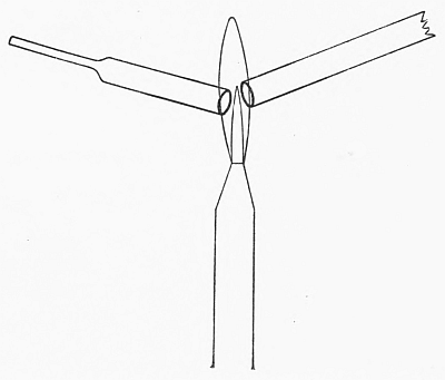
Fig. 5.—Softening ends of two pieces of tubing.
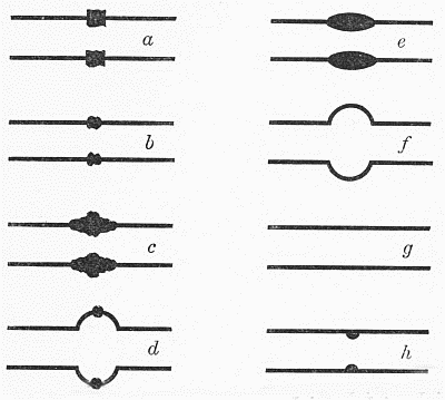
Fig. 6.—Joining two pieces of tubing end to end—first method.
As the tube softens and tends to shrink, the two ends
are pressed together a little and the walls allowed to[Pg 18]
thicken slightly, as in c. It is then quickly removed
from the flame and gently blown as indicated in d,
continuing the rotation of the tube during the blowing,
and at the same time pressing the ends of the tube together
a little so as to make a short thick-walled bulb.
The joint is then returned to the flame and reheated,
rotating as before, shrinking to about the shape of e.
When this stage is reached, the glass should be very hot
and fluid, and the mass of hot glass thick enough to
remain at its working temperature for about five seconds
after removal from the flame. The glass is now reblown
as indicated in f, to form a bulb having walls of practically
the same thickness as the original tube. As soon as the
bulb is blown, the tube is removed from the mouth, held
horizontally in front of the worker, and gently drawn out
to form one continuous tube, as indicated in g. During
both the blowing and drawing of this bulb the rotation
must be continued, and both blowing and drawing must
be carefully regulated so that the resulting tube may have
the same internal and external diameter at the joint as
elsewhere.
Discussion.—In making the original joint, (a, Fig. 6),
care should be taken that the lump formed is as small as
possible so that it may be entirely removed during the
subsequent operations. For this reason, only the very
tip ends of the two pieces of tubing are held in the flame,
and the softening should not extend more than 1⁄16
inch down the tube. As soon as the ends are sufficiently
soft to stick together, they are made to do so. The first
drawing of the tube (b) should take place immediately,
and reduce the lump as much as possible without making
the adjacent walls of the tube thin. The whole purpose
of the rest of the manipulation is to absorb or “iron out”
the lump at the joint. For this reason, care is taken that
this lump is always in the center of the flame while the[Pg 19]
joint is being heated, and a small flame is used so that
little of the main tube may be softened. During the first
shrinking of the joint (c) the walls next the lump, being
thinner than it is, reach the softening temperature first
and are thickened by the slight pushing together of the
ends, so that they taper from the lump to the unchanged
wall. Upon blowing this joint, these thickened walls
blow out with the lump, but as they are thinnest next the
unchanged tube, they stiffen there first. Then as the
thicker parts are still hot, these blow out more, and with
the lump make a more or less uniform wall. By this first
operation most of the lump will have been removed, provided
it was not too large at first, and the tube was hot
enough when it was blown. Beginners almost invariably
have the glass too cool here, and find difficulty in blowing
out a satisfactory bulb. Under such circumstances the
lump will be scarcely affected by the operation.
During the shrinking of this bulb, the thinner parts of
course are the first to reach the softening point, and thus
contract more than the thick parts, so that practically all
of the lump can be absorbed, and a uniformly thickened
part of the tube left as in e. When this is just accomplished,
the second bulb must be blown during one or
two seconds, and the tube then drawn out as described,
so as to change the bulb to a tube. The drawing must
proceed with care: portions nearest the unchanged tubes
are the first to reach the proper diameter, and must be
given time to just set at that point before the center of
the bulb is finally drawn into shape. The drawing is
perhaps best done intermittently in a series of quick
pulls, each drawing the tube perhaps 1⁄16 inch, and each
taking place as the thumbs and first fingers grasp the tube
for a new turn in the rotation. If the tube is not rotated
during the blowing, the bulbs will be lop-sided and it will
be impossible to get a joint of uniform wall-thickness;[Pg 20]
if rotation is omitted during the drawing, the tube will
almost invariably be quite crooked.
If the lump still shows distinctly after the operations
described, the cross-section of the tube will be as in h, and
the tube will be likely to break if ever reheated at this
point after it becomes cold. The operations d, e, f, and
g may be repeated upon it, and it may be possible to get
it to come out all right.
Care must be taken not to blow the bulbs d and f too
thin as they then become very difficult to handle, and the
joint is usually spoiled. The wall-thickness of these
bulbs must never be much less than that of the original
tube. If the joint as completed has thinner walls than
the rest of the tube, it will be more easily broken. It
should be remembered that the length of the finished
tube must be exactly the same as that of the original
piece, if the walls of the joint are to be of their original
thickness. Therefore the pushing together during the
two operations c and d must shorten the tube just as
much as the final drawing (f to g) lengthens it.
The interval between the removal of the work from
the flame and the beginning of the blowing must be made
as short as possible, or else the portions next the main
parts of the tube will set before they can be blown out,
and cause irregular shrunken areas.
EXERCISE NO. 2
Joining Two Tubes End to End—Second Method
The method described in Exercise No. 1 is very satisfactory
for joining short lengths of straight tubing, but
becomes inconvenient or impossible when the pieces are
long or bent, on account of the difficulty in uniformly
rotating such work. In such cases, this second method is[Pg 21]
used. It does not usually give as smooth and pretty a
joint as the first method, and takes a little longer.
The joint is begun exactly as in the first method, and
the manipulation is the same until after the preliminary
tight joint (b, Fig. 6) is made. The flame is reduced as
usual, but instead of rotating the tube in the flame, only
one part of the circumference is heated, and this is
allowed to shrink thoroughly before blowing. It is then
blown gently so that it becomes a slight swelling on the
tube, and the operation repeated on an adjoining part of
the joint. Three or four repetitions of the operation will
usually cover the whole circumference of the joint, in a
small tube, the result being a swelling roughly similar
to the first thick bulb in the first method (d, Fig. 6). If
all the lumps of the original joint have not been removed
by this operation, it may now be repeated upon such parts
as may require it. The thickness of the wall in the bulb
should be about the same as that in the original tube.
The whole of the expanded joint is now heated as uniformly
as may be until soft enough so that it begins to
shrink a little, and the swelling is gently drawn down to
the same diameter as the main tube, as in the first case.
Any irregularities in the finished joint may be corrected
by local reheating, shrinking or blowing as required.
Discussion.—In using this method, especially with
larger sizes of tubing, it is very important to keep the
whole circumference of the joint hot enough during the
operation so that it does not crack apart at the part
which has not yet been worked. For that reason the
first heating, shrinking and blowing should be performed
as quickly as possible, leaving the resulting irregularities
to be corrected later, rather than attempting to reblow
the same part of the joint several times in succession
until it is satisfactory. Care must be taken in this as in
the first method that the blowing follows immediately[Pg 22]
upon the completion of the shrinking and removal of
the object from the flame: delay in blowing will cause
shrunken places where the joint meets the original tubes,
on account of the cooling and setting of the glass before
it was blown. Most beginners err in being afraid to
shrink the part of the joint enough before blowing it.
On small tubing, the shrinkage may often extend so far
that the inner surface of the shrunken part reaches the
center of the tube. Insufficient shrinking results in
failure to remove the lump formed at the original joint.
It is often of advantage, after blowing out part of the
joint, to allow that part a few seconds to set before going
on with the rest, keeping the whole joint warm meanwhile
in or near the smoky flame. This helps to prevent the
twisting of the joint, or other distortion incident to the
handling of a piece of work of awkward shape.
In making a joint on a very long or heavy piece by
this method, it is often advantageous to attach a piece
of rubber tubing to the open end, hold the other end of
this tubing in the mouth during the process, and blow
through it, rather than attempt to bring the end of the
glass up to the mouth. This enables one to keep closer
watch on the joint, and avoid drawing it out or distorting
it in handling. On the other hand, the rubber tube is an
inconvenience on account of its weight and the consequent
pull on the end of the apparatus, and makes rotation
difficult.
EXERCISE NO. 3
The “Tee” Tube
The operations involved are two: the blowing of a
short side tube on a piece of tubing, and sealing another
piece of tubing on this, by what is essentially the second
method as just described.[Pg 23]
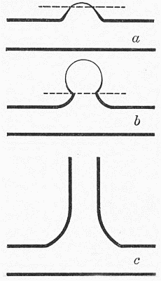
Fig. 7.—The “tee” tube.
The two pieces of tubing to be used each have one end
cut square and the other sealed in the usual manner.
The longer of the two is now heated at the point at which
the joint is to be made, until it begins to color the flame.
A small flame is used, and the tube rotated until the
flame begins to be colored, when the rotation is stopped,
and only one spot heated until a spot the diameter of the
tube to be sealed on has become red hot and begun to
shrink. This is now gently blown out into a small bulb,
as in a, Fig. 7, and it will be noted
that this bulb will have walls tapering
from the thick walls of the
tube to a very thin wall at the
top. The sides of this bulb, below
the dotted line, are to form
the small side tube to which the
main side tube is to be sealed.
The top of the bulb is now softened
by directing a small flame
directly upon it, and as soon as
it shrinks to the level indicated
by the dotted line, it is removed
from the flame and quickly blown
out to form a thin bulb, as indicated
in b, Fig. 7. This will usually
be so very thin that a stroke of the file or glass-knife
will break it off at the dotted line, leaving the
side tube, to which the short piece of tubing is now
sealed according to the second method (Exercise No 2).
In doing this, care is taken to direct the flame partly on
the main tube in the two crotches, so that both tubes blow
out a little and give space for the gases to turn in, as
indicated in c, Fig. 7, and at the same time increase the
mechanical strength of the job. On the other hand,
care is taken not to deform the main tube, and not to[Pg 24]
produce such a bulge or bulb at the joint as will prevent
the finished tube from lying flat on a table.
Discussion.—Most beginners tend to err in the first
steps of this operation, by blowing too hard and too long
when blowing out the little bulb. The result is a large,
very thin bulb, which breaks off in such a way as to leave
a hole in the main tube, occupying nearly half the circumference
of the tube at that point, instead of the neat
side tube which they should have. It is not difficult to
seal a tube on this side tube, but it is very difficult to seal
a tube into a hole in another tube. Care should be taken
here, as in the two previous exercises, that the lump
obtained at the joint when the two tubes are put together
is made as small as possible, and reduced if possible by
gently drawing on the side tube as soon as the tubes have
actually joined. It is much easier to prevent the formation
of a lump at the joint than it is to remove the lump
after it is formed. The remarks previously made about
blowing quickly after removing the work from the flame
apply here with especial force. A “tee” tube, from its
very nature, is exposed to a good many strains, so care
must be taken that the walls of the joint are of uniform
thickness with the rest of the tube.
The beginner will find it easiest to make this tube out
of two pieces of the same tube, about 1⁄4 inch in diameter.
Larger or smaller tubing is usually more difficult. If
tubing much more than 1⁄4 inch is used, the whole joint,
including part of the main tube, must be heated nearly
to the softening point at the close of the operation, and
well annealed, as described in Chapter 1 (page 3) or it
will be almost certain to crack. In the larger sizes of
tube it will be necessary to heat the whole circumference
of the main tube frequently during the operation, to
prevent it from cracking.
In sealing a small tube on the side of a large one, it is[Pg 25]
usually advisable, after warming the spot where the joint
is to be made, to attach a small drop of glass to the tube
at that point, and direct the flame upon that, thus supplying
at the same time both a definite point to be heated
and an extra supply of glass for the little side tube which
is desired. In this way it is also easier to blow out a
side tube with a sufficiently small diameter. If the
diameter of this tube should be much greater than that
of the small tube, the latter may be enlarged with a
carbon or a flanging tool.
EXERCISE NO. 4
To Join Two Tubes of Different Diameters
In this case the first method (Exercise No. 1) is to be
used whenever possible, as it gives a much smoother joint
than the second method. The directions given will
describe the adaptation of this method to the problem:
if the second method must be used on account of awkward
shape, etc., of the work, the modifications required
will be obvious to any one who has learned to make the
joint by the first method.
After sealing or corking one end of the larger tube, the
other end is drawn out to form a tail as described on page
9, taking care to have the tube uniformly heated, and
to draw the tail rapidly enough so that the cone is short,
as indicated in a, Fig. 8. The tube is now rotated, a
small flame directed against the cone at right angles
to an element of it, and it is allowed to shrink a little,
as indicated in b, Fig. 8, so that its walls will thicken.
When the tail is cut off, at the dotted line, the diameter
of the opening and the thickness of the walls at that point
should correspond with the dimensions of the tube to be
sealed on. As the glass is hot, the scratch for cutting it
must be made with a file (moisten the edge!), and it[Pg 26]
often will not break square across. Before proceeding
to seal on the small tube, any large projections on the
cut end are best removed, by warming the cut surface a
little, directing the small flame upon each projection in
turn and touching it with a warm scrap of glass. It will
adhere to this and may then be removed by rotating this
scrap a little so as to wind up the projection on it, and
then drawing it off, while the flame is still playing on the
spot. This must be done rapidly and care taken not to
soften the main part of the cone.
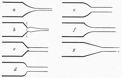
Fig. 8.—Joining two tubes of different diameters.
The large tube is now taken in the left hand, the small
one in the right, the ends heated and joined in the usual
manner, taking care not to get any larger lump at the
joint than necessary. A small flame is now directed on
the cone at right angles to its elements as before, and the
tube rotated so as to heat the whole circumference. The
flame should be just large enough to heat the whole of
the cone. As the latter shrinks, the lump at the joint
is brought into the edge of the flame, and it and a very
little of the small tube allowed to shrink with the cone.
When well shrunk and heated to blowing temperature[Pg 27]
the joint is removed from the flame and blown gently
with careful rotation, pushing the tubes together a little
when the blowing is about finished, so that the cone
becomes a short thick half-bulb, as shown in d, Fig. 8.
This corresponds to the first thick bulb in the first method
(d, Fig. 6), and is treated similarly. It is again heated
and shrunk, taking care not to involve either the large
tube or the small one in the shrinking, blown quickly to
about the same shape as before, (d, Fig. 8), and then
gently drawn out into a smooth cone (e), exactly as in the
first exercise. Care should be taken not to draw too
rapidly or too far, as then the resulting cone (f) is weaker
than it should be, and does not look well.
Discussion.—The beginner will find that this operation
is best learned on two tubes which are not too nearly of
the same diameter. A tube about 5⁄8 inch in diameter
and one a little less than 1⁄4 inch will be suitable. Both
should have moderately heavy walls (1⁄16 inch or a
trifle over for the large tube, and a trifle less for the small
one) but the large tube should not be too heavy or else it
will be hard to prevent melting down too much of the
small tube, and getting this drawn out too thin during the
process. One of the troublesome features of this exercise
is the difficulty of rotating two tubes of different diameters
with the same angular velocity, so as not to twist the
joint. Another difficulty is found in getting the cone
uniformly heated to blowing temperature without overheating
and overshrinking the small tube. The reason
for this is obviously the much greater circumference of
the cone, especially at its large end, so that relatively
much less of it is being heated at any time. The beginner
is also inclined to start with too long a cone, or else heat
so much of the large tube that part of its glass is included
in the cone, with the result that in order to get the[Pg 28]
right wall-thickness the cone must be made too long (g,
Fig. 8). This does not look well, and usually will be
irregular in shape.
EXERCISE NO. 5
Tube for Condensing Sulphur Dioxide
This is useful as a test of mastery of the preceding
exercise. A piece of 3⁄16 or 7⁄32 inch tubing is joined
to each end of a piece of tubing 5⁄8 by about 5 inches, and
two constrictions made in the large tube, by the method
described on page 10. The small tubes are then bent
in the same plane, as shown, and their ends fire-polished
(Fig. 9).
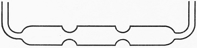
Fig. 9.—Tube for condensing sulphur dioxide.
EXERCISE NO. 6
Bulb at the End of a Tube
For this exercise tubing of 1⁄4 inch diameter and moderately
strong walls is selected. A tail is drawn out on one
end of the tube, and a piece of tubing about nine or ten
inches long is cut off. The tail should be carefully drawn
in the axis of the tube, and in the same straight line with
it, as it is to be used as a handle in assembling the glass
for the bulb. This tail must be long enough so that it
can be conveniently held in the left hand, as described on
page 13, and rotated about the same axis as the main
tube. Holding the main tube in the right hand and the
tail in the left, the tube is rotated in a large flame so[Pg 29]
that a piece of it, beginning where the tail stops and
extending about an inch to the right, may be uniformly
heated to the highest temperature at which it can be
kept in shape. As soon as
this temperature is reached,
the tube is removed from the
flame, continuing the rotation
and taking care not to draw
out the heated part, and
gently blown. The rotation
is carefully continued during
the blowing, holding the tube
in approximately a horizontal
position. As soon as the tube
has expanded a little the tail
is pushed gently toward the
main tube, continuing the
gentle blowing. If this is
properly done, the heated
piece of tube will become a
short bulb of about double its
original diameter, and about
the same wall thickness as the
original tube. It will have
somewhat the appearance of
a, Fig. 10, when properly manipulated.
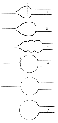
Fig. 10.—Blowing a bulb on
the end of a tube.
The tube is now reheated as before, taking care this
time that the heating extends over all that part of the
bulb to the right of the dotted line in the figure, as well
as part of the main tube adjoining. If this heating has
been properly placed, when the operation of blowing and
pushing together is repeated the result will be to lengthen
the bulb into a uniform cylinder, as shown in b, Fig. 10.
Otherwise the result will be a series of bulbs, as in c,[Pg 30]
Fig. 10, separated by thickened ridges which will be
almost impossible of removal later and will disfigure the
final bulb. This operation of heating, blowing and
pushing together is repeated several times, until the
cylinder becomes as long as can be conveniently handled
(about 1-1⁄4 inches to 1-1⁄2 inches). If more glass is
needed than is then contained in the cylinder, the latter
may now be heated as a whole, and blown and pushed
gently into a shorter cylinder of a slightly greater diameter,
and more glass then added as before.
When enough glass has been collected for the bulb, it
is all well heated and blown gently a couple of times,
pushing the mass together as required, until a thick bulb
like d, Fig. 10, is obtained. The tail must now be
removed at the point indicated by the dotted line. To
do this, a very fine flame is directed on the point where
the tail joins the bulb, and the tube well rotated as the
glass softens at that point. When sufficiently soft, the
work is raised a little, so that the flame instead of striking
the glass squarely at the point indicated passes below and
tangential to it. The tail is now drawn off slowly, continuing
the rotation, raising the work just out of the
flame whenever the thread of glass drawn off becomes too
thin, and lowering it again to the point where the flame
just touches it when the glass stiffens a little. By this
means the tail may be drawn off without leaving an
appreciable lump behind, as indicated in e and f, Fig. 10.
When as much of the extra glass has been removed as is
practicable, the flame is brought to play squarely upon
the little lump left, the last of the tail removed, and the
lump heated and gently blown to a small excrescence on
the main bulb. The whole end of the latter is now heated
until it begins to shrink a little, and gently blown to
make it uniform in thickness. The whole bulb is then
heated in a flame of the proper size, so that it all may[Pg 31]
shrink to about two-thirds of its diameter. The flame
must be very carefully chosen and directed, so as to
shrink all the bulb, right up to the main tube, but not
soften the latter. As soon as this stage is reached, the
bulb is removed from the flame, continuing the even
rotation, and blown to the desired size, preferably by a
series of gentle puffs following one another at very short
intervals. During the blowing, the main tube is held in
a horizontal position, and any tendency of the bulb to
fall out of line is corrected by the rotation. If the shape
of the bulb or its size are not satisfactory, it may be
shrunk again and reblown. Such shrinking should begin
in a large yellow flame, with just enough air to give it
direction. The amount of air may be gradually increased
as the bulb shrinks and the walls become thick enough to
bear it without collapsing. If the bulb starts to collapse
at any time, it must be immediately blown enough to
regain its convex surface, before the shrinking proceeds
further.
Discussion.—In collecting the glass for the bulb,
enough must be gathered to give the walls the desired
strength. Since the area of a sphere is proportional to
the cube of its diameter, it is evident that doubling the
size of a bulb diminishes the thickness of its walls to a
very large extent. The limit of diameter for a strong
bulb on ordinary 1⁄4-inch tubing, collecting the glass as
above, is about 1-1⁄2 inches, and the beginner will do well
not to blow his bulbs more than an inch in diameter.
The collection of the glass is one of the most important
parts of the process. If the mass of glass be twisted, furrowed
or ridged, or lop-sided, it is very difficult to get a
good, even, spherical bulb, no matter how many times it
is shrunk and blown. The greatest care should therefore
be taken to get a uniform cylinder, on the same axis as
the main tube; and to this end the rotation of the tube[Pg 32]
must be carried on very evenly. For method of holding
the tube, see page 14.
If a very large bulb is required, it will often be economical
to seal on the end of the tube a short piece of a large
tube, provided with the proper tail, and use the glass in
the large tube for the bulb instead of attempting to collect
it from the small tube. In this case part of the small
tube will usually be included in the bulb, so that the joint
comes in the latter, and not where it joins the tube. As
the amount of glass carried on the end of the tube
increases in weight and size the difficulties of heating it
uniformly, keeping it in the proper position and handling
it increase rapidly.
In collecting glass, it is usually best not to leave the
part of the cylinder next the tube with too thick walls.
This is always the coolest part during the preparation for
blowing the bulb, consequently it does not get blown out,
and causes an ugly thickened appearance on that end of
the bulb.
If the bulb grows too long or pear-shaped, it may be
easily shortened by heating to the blowing temperature,
and then blowing gently with the main tube in a vertical
position, and the bulb at the top of it. Gravity will then
shorten the bulb nicely.
The finished bulb should be a nearly perfect sphere,
with the axis of the tube passing through its center, and
the portion of the tube adjoining the bulb must not be
distorted, twisted, or blown out. In order to prevent the
distortion of the tube, care must be taken that it is never
heated quite to its softening point during the process.
EXERCISE NO. 7
Blowing a Bulb in a Tube
The tube is selected and one end closed as in the previous
exercise, but it should be cut a little longer, say[Pg 33]
about twelve inches. Beginning at a point about four
inches from the closed end, glass is collected and blown into
a thick-walled bulb, exactly as in the previous exercise.
Greater care must be taken, however, that the cylinder
collected and this thick bulb are of uniform thickness and
set squarely in the axis of the tube. Instead of removing
the tail, the bulb must be blown in this case with both
pieces of tubing attached, and care must be taken that
they “line up” properly, i.e., are in the same straight
line, and that this line passes as near as may be through
the center of the bulb. The tube is held in approximately
horizontal position during the blowing of the bulb, as in
the previous case, and especial care taken with the rotation.
Both pieces of tube must of course be rotated at
the same rate, and their softened ends must be kept at
exactly the proper distance from each other, so that the
bulb may be spherical and not elongated. If the blowing
of the bulb be quickly and accurately done, it may
usually be completed before the glass is quite set, and the
alignment of the two tubes may then be rectified while
looking straight through the bore of the tube.
Discussion.—The two points of greatest importance
are the collection of the glass, and the uniform rotation
of the tube. A larger tube may be sealed in the middle of
a small one when a large amount of glass is necessary.
The piece of tubing used for the exercise must be long
enough so that the fingers may be kept on a cool part of
the glass without getting uncomfortably near the ends
of the tube. It should not be any longer than necessary,
however, as the extra weight and length make the manipulation
of the hot glass more difficult.
When a string of bulbs are required on the same tube, a
piece of glass 18 inches long may be used at the start,
and the first bulb made near the closed end, as described.
Each succeeding bulb will then be in plain view during the[Pg 34]
blowing, and when the open end becomes too short for
comfort, it may be dried out, cut off, and another piece
joined to it, starting as in the first method (Exercise
No. 1), but instead of drawing out the thick bulb to a
tube, it is made part of the glass collected for the next
bulb. If the string of bulbs becomes awkward to handle
on account of its length and weight, it may be made in
several parts and these later sealed together by the second
method, preferably blowing through a rubber tube attached
to the open end, as described on page 22.
Very neat small bulbs may be made on tubing of a
diameter of 3⁄16 inch or a little less, but the beginner is
advised to start with tubing of about 1⁄4 inch diameter.
The use of tubing with too thick walls usually produces
bulbs which are thick-walled at the point where they
leave the tube, but inclined to be too thin at the point of
maximum diameter (perpendicular to the axis of the tube)
where most of the strain comes and strength is particularly
needed.
CHAPTER IV
Advanced Exercises
EXERCISE NO. 8
Sealing a Tube Through Another Tube
First Method—Making a Gas-washing Tube
This first method can be used whenever one can work
through an open end opposite to the end of the tube
where the joint is to be made. To illustrate it, take a
piece of rather thin-walled tubing, about 3⁄4 inch in
diameter, and some pieces of rather strong tubing a little
less than 1⁄4 inch in diameter. Draw off the large tube
in a short cone, then draw off the tail as in the making of
the bulb on the end of the tube, blow out the little lump
slightly, shrink the whole cone a little and blow gently to
form a rounded end like that on a test-tube, with walls
about the thickness of those of the rest of the tube. Cut
this tube to a suitable length, say about six inches, and provide
two corks which will fit the open end of it. Now cut
a piece of the small tubing of the proper length to form
the piece which is to be inside the large tube. For practice
purposes, this piece should be about an inch shorter
than the large tube. Flange one end of this tube a little,
and anneal the flange well in the smoky flame. Bore one
of the corks so that a piece of the small tubing will fit it,
and cut a couple of notches in the side of this cork so that
air can pass between it and the glass. Pass a short piece
of the small tubing through this cork, and attach the[Pg 36]
flanged piece of small tube to this by means of a short
piece of rubber tubing, so that when the whole is inserted
in the large tube it is arranged as in a, Fig. 11. The piece
of glass tubing projecting out through the cork is now cut
off so as to leave an end about 1⁄2 inch long when the
cork is firmly seated and the inner tube pushed into
contact with the center of the end of the large tube, as
shown in the drawing. Care should be taken that the
little rubber tube which joins the two pieces is arranged
as in the figure; i.e., most of it on the piece of tubing which
passes through the cork, and very little on the other
piece, so that when the cork is removed after the small
tube has been sealed through the large one, the rubber
tube may easily come with it. Select a short piece of the
small tubing of suitable length for the piece which is to[Pg 37]
be on the outside of the large tube as a continuation of
the piece inside, and another piece for the delivery tube.
A small bulb may be blown in the latter at a point about
2-1⁄2 inches from the closed end, and the open end cut
off about 1-1⁄2 inches from the bulb. A cork or cork-boring
of suitable size to stopper the small tube is prepared,
and laid ready with the other (unbored) cork for
the large tube.
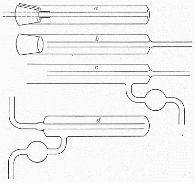
Fig. 11.—Gas-washing tube.
When everything is in readiness, the rounded end of the
large tube is slowly heated until it softens and joins firmly
to the small tube inside. After it has shrunk down well,
it is blown out to its original size, placing the whole end
of the large tube, cork and all, in the mouth. Now with a
fine-pointed flame the glass covering the end of the small
tube is heated to the softening temperature, and then is
blown out to an excrescence by blowing on the end of the
small tube which passes through the cork. The end of
this excrescence is heated and blown off in the usual way,
so as to leave the small tube sealed on the inside of the
large one and opening through it into this short tube which
has been blown out. The end of the small tube which
passes through the cork is now closed with the cork prepared
for it, and the short outer tube is joined to the tube
that has just been blown out, so that the joint appears
like b, Fig. 11. Use the first method (Exercise No. 1)
for this joint. Reheat the whole of the end of the tube
nearly to the softening temperature, anneal it a little,
and allow to cool a few seconds until well set. Now
remove the cork, short glass tube and rubber tube from
the open end of the large tube and insert the solid cork
in their place. Warm the joint and the whole of that
end of the tube again carefully up to about the softening
point, then seal on the side tube for the delivery of the
gas in the usual way, taking care that the whole of the
end and the joint are kept warm meanwhile. When[Pg 38]
thoroughly sealed, the delivery tube is bent up parallel
to the tube through which the gas enters, and then out
at right angles to it, as shown in c. The whole of the
end of the tube is now cautiously reheated and then cooled
slowly to anneal it.
The cork may now be removed from the open end of
the large tube, this end heated in a large flame, caught
together with a scrap of glass tubing and drawn off into
a cone so that the base of the cone is about opposite the
end of the inner tube. The lump of glass is drawn off the
point of this cone and it is reblown to form a rounded
end, as previously described.
After this cools, the tube through which the gas enters
may be heated at the proper point and bent at right
angles to form the finished apparatus as shown in d.
The ends of the small tube are cut off square and fire-polished.
Discussion.—After the joint has once been made, great
care must be taken that it is kept hot during all the subsequent
manipulations, and if it becomes somewhat
cool at any time it must be reheated very slowly. It is
obvious that the rate of heating and cooling of the inner
tube will be slower than that of the outer tube, and this
will readily produce stresses which tend to crack the tube
at the joint. The amount of heating and cooling which
such a joint will stand depends upon its form. The
beginner should examine such a joint on regular factory-made
apparatus, and note the uniformity of wall-thickness
and the “clean-cut” appearance of the joint, as a
model for his imitation. A ragged joint, where the line
of joining of the inner and outer tubes wavers instead of
going squarely around the tube, is almost sure to crack
during the cooling and heating unless extra precautions
are taken with it. The presence of a small lump of glass
at any point on the joint affords an excellent starting[Pg 39]
place for a crack, as do also the points on a ragged joint
where the inner tube comes farther down on the outer
tube than at other points.
In order to insure a joint which is square and not
ragged, it is essential that the angle between the inner
and outer tubes at the joint be very nearly a right angle.
For this reason the two tubes should not be of too near
the same size, or if this cannot be avoided, a small bulb
should be blown on the end where the joint is to be made.
If this bulb be made with the same wall-thickness as the
rest of the tube, and somewhat pear-shaped, it may be
drawn out to the same size as the rest of the tube, if
necessary, after the joint has been made.
This method is used wherever possible in preference to
the second method (Exercise No. 9), as it is easier to get
a good joint with it. It may also be used where it is
desired to seal the tube through the side of a tube, or for
a tube sealed through the wall of a bulb, as in a Geissler
potash bulb or similar apparatus. Where there is not
space to join the inner tube to the blowing tube by a
rubber tube, this joint may be made with a small piece
of gummed paper, which can readily be broken when
desired.
EXERCISE NO. 9
Sealing a Tube Through Another Tube
Second Method—Making a Suction Pump
Select a piece of tubing 3⁄8 to 1⁄2 inch in diameter,
with walls about 1⁄16 inch or a little less in thickness,
heat a place about 4 inches from one end and draw it
out so that when cut off at the proper point it will look
like a, Fig. 12; the open end of the drawn out part being
small enough to slip inside another piece of the original
tube. A small thick-walled bulb is now blown as[Pg 40]
indicated by the dotted lines, and annealed. A piece of
the original tubing is now prepared, 7 or 8 inches long,
with one end cut square off and the other closed. A
piece of 1⁄4-inch tubing about 2 inches long, and drawn out
at one end to a tail several inches long is also prepared, to
form the inlet tube for the air. Another piece of the
3⁄8-inch tube is prepared, about 4 inches long, and provided
with a tail drawn out as indicated in b, so that when
cut off at about 2-1⁄2 or 3 inches from the main tube its
inner diameter may be slightly less than that of the narrowest
point of the tube a. A small thick-walled bulb
is blown at the point indicated by the dotted lines, and
annealed. Care must be taken in drawing the capillary
and blowing the bulb in both a and b that the capillary
tubes are in the axis of the main tube, and in the same
straight line with it.
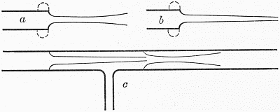
Fig. 12.—Suction pump.
The open end of the 8-inch piece of tube and the bulb
of the piece a are now warmed together, the end of the
tube only moderately and the bulb to about its softening
temperature. The tube a is now inserted in the open end
of the large tube, and the bulb softened with a suitable
flame and pressed into good contact with the tube. It
is then reheated, including the joint, blown a little and
pulled out to form a straight tube in line with the main
tube. By warming the joint a little, and proper rotation,[Pg 41]
the capillary may be brought into the same straight line
with the rest of the tube.
Keeping this joint hot, a place about an inch from it on
the tube a is warmed, and the piece of 1⁄4-inch tubing
previously prepared is sealed on at that point. The
joint is then well annealed and allowed to cool.
The tube a is now cut at such a place that when b is
inserted in the open end the point will come near the
end of the constriction of a, as shown in c. Care is
taken to get a clean square cut. The side tube is now
cut off about an inch from the main tube and corked.
Tube b is sealed into the open end of a, in the same way as
a was sealed into the large tube, and the joint carefully
annealed.
Discussion.—As in the first method, the secret of success
lies in getting a square joint, and having the inner
tube leave the outer one at nearly right angles. All the
remarks about annealing, lumps, etc., made under the
previous method apply here.
This method may be applied in sealing a small tube
into the end of a large one, the latter being either drawn
to a cone and cut off at the desired diameter, or else
given a rounded end like a test-tube and a hole the proper
size blown in the center of it. A suitable thick-walled
bulb is to be blown on the small tube, as in the case
described above. This method is also used in making
the Kjeldahl trap (a, Fig. 13), the small tube to be
inserted being first drawn, the thick bulb blown at its
point of union with the main tube, and then the small
tube bent and cut. The large bulb is best made with
rather heavy wall, being either blown in the middle of
a tube, and one piece of the tube drawn or cut off, or
else made on the end of a tube. In the latter case a drop
of glass must be put on the point where the joint is to
be, so as to get a hole of the proper size with enough glass[Pg 42]
around it to prevent it from growing larger when it is
heated. The author prefers to blow the bulb in the
middle of the tube, draw off one end of the bulb, and
blow out the desired hole where the tube was drawn off.
The whole bulb must generally be reheated and blown
a little at the end of the process, and well annealed.
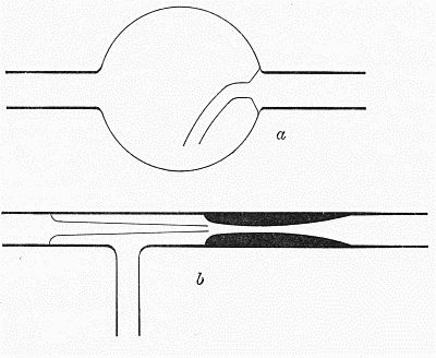
Fig. 13.—a, Kjeldahl trap; b, suction pump on smaller tubing.
The suction pump can also be made on 1⁄4-inch tubing,
and one joint saved if desired, by constricting the tube
to form the raceway for the water and air, as shown in
b, Fig. 13. (See page 10 for method.) But it is more
difficult to make a square joint on such small tubing.
CHAPTER V
Modified Methods and Special Operations
CAPILLARY TUBING
This is commonly used in many forms of apparatus
for gas analysis, and one is often called upon to join two
pieces or to make a tee on it. The methods are nearly
the same as with other tubing, except that more care and
patience are required. The work must be done much
more slowly on account of the thickness of the walls, and
open ends of the tube must always
be enlarged before joining them to
anything. This is best done by carefully
sealing the end and then blowing,
with several suitable reheatings, to
form a pear-shaped bulb as in a, Fig.
14. The end of this is then heated
and blown off, and the piece is ready
to be joined to another similar end, or
to a piece of ordinary tubing if desired.
The joints are best not blown
too much, as thick walls shrink very slowly. Much may
be done by gently pushing the tube together or pulling
it apart in the flame, to remove lumps and irregularities.
It is necessary that the bore of the joint be approximately
that of the main tube, and care must be
taken that the latter is not constricted at the point
where the joint begins.
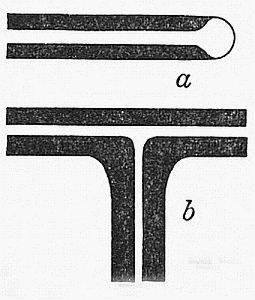
Fig. 14.—Capillary
tubing.
Especial care must be taken to warm the tube slowly
when starting and cool it slowly when through, as the[Pg 44]
thick walls frequently crack if not carefully handled.
For this reason the whole neighborhood of the joint must
be heated somewhat so that there may not be stresses set
up between the heated and unheated portions.
In making the tee (b, Fig. 14) the inability to blow the
joint makes itself decidedly felt, but if the side tube is
properly enlarged as previously described, a good joint
can be made by alternately pulling and pushing on the
end of the side tube, and shrinking well.
Very fine capillary tubing should be blown with a
rubber bulb instead of the mouth, so as not to get
moisture into the tube. The rubber bulb may also be
used to advantage on some of the coarser capillary
tubing.
When a bulb is to be joined to a piece of capillary
tubing, the joint is preferably made before blowing the
bulb, and will then be taken up a little way on the bulb
during the process. Care must of course be taken not to
constrict the capillary; the pear-shaped bulb blown on
the end (a, Fig. 14) may well extend back a little further
than usual into the tube so as to prevent this. If a bulb
is required in the middle of a capillary tube, the latter
is usually best cut and a piece of ordinary tubing of suitable
size sealed in to provide material for the bulb.
GLASS ROD
Joints, tees, etc., in glass rod are made on the same
principle as in tubing, except that of course they cannot
be blown, and regularity must be obtained by accumulating
a small mass of uniformly heated glass, and then
drawing it to a suitable rod, on the same principle as
Exercise No. 1.
Great care must be taken in heating and cooling this,
as in the case of the capillary tubing, and for the same
reasons.
By joining pieces side by side, pressing with carbon[Pg 45]
plates or a plate and a rod, and other suitable manipulations,
stirrers, spatulas, and other objects may easily
be made from rod, and its manipulation is relatively easy
on account of the fact that one does not have to worry
about the bore of the tube. But the same general rule
about not having thick and thin spots in contact, and
making all changes in diameter on a taper if possible
instead of abruptly, applies here. Thick pieces will cool
and contract at different rates from thin ones, and cracks
are likely to develop where they join. Work which
has been formed with any tool must always be heated to
the softening point afterward before allowing it to cool
in order to remove the stresses caused by the contact of
the tool with the hot glass.
When it is necessary to join a piece of rod to the side
of a piece of tubing, the end of the rod is made very hot
while the wall of the tube at the spot desired is heated to
just below the softening temperature. The rod can then
be pressed into firm union with the tube and drawn a
little to remove the excess of glass without deforming the
tube.
MENDING STOPCOCKS
Mending the Plug.—The plug of the stopcock occasionally
falls out and is broken. If the break is in the
main part of the plug, nothing can be done except to
search for a spare plug of suitable size and grind it to
fit, as described below. If only the little cross-piece at
the end is broken off, it can easily be replaced. In
most ordinary stopcocks the plug is solid, but the little
handle is hollow. What has been said above regarding
care in heating and cooling glass rod applies with especial
force here. It is usually best to wind the whole of the
plug with several thicknesses of asbestos cord, leaving[Pg 46]
bare only the end where the handle is to be joined. This
diminishes the danger of cracking the plug by too rapid
heating, and also makes it more comfortable to hold. A
piece of rather thick-walled tubing of suitable diameter is
chosen, drawn out so as to have a suitable taper (taking
care to heat enough of the tube so that the capillary tail
has good wall-thickness and strength), and then a
corresponding taper is drawn to form the other side
of the handle. The result is shown in Fig. 15, a. The
capillary tail is now heated and bent back to form a
handle which will be in the same straight line as the axis
of the plug (b, Fig. 15) and the main part of the tube
drawn off at the dotted line, making a neat seal at that
point. The broken end of the plug is now slowly warmed
in the smoky flame, the heat gradually increased by a
gentle stream of air from the bellows, and the point at
which this handle is to be attached finally brought to
the temperature at which the glass flows freely. In the
mean time, the little handle has been warmed almost to
the softening point. It is now quickly pushed into place
(c, Fig. 15), taking care that its axis is parallel to the hole
in the plug, and then drawn away from the plug just
enough to make a graceful neck instead of the bulging one[Pg 47]
indicated by the arrow in the figure. With a fine pointed
flame the little tail is now drawn off at the point indicated
by the dotted line (c, Fig. 15) and the whole carefully annealed.
If necessary, the handle can be blown a little
before the tail is removed. Local heating and blowing at
the point where the handle joins the plug is often necessary
in order to make a smooth job.
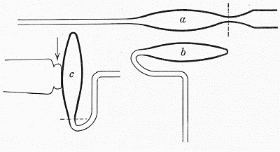
Fig. 15.—Stopcock plug.
Regrinding.—This is sometimes necessary to make
stopcocks tight, when the grinding has not been properly
done in the factory. For this, a very little fine flour of
emery or carborundum is the best and quickest. If this
is not at hand, some clean sand may be ground in an agate
mortar, and if possible sieved. Only material which
passes the 100-mesh sieve should be used. It will be
ground still finer in the process. For the final polishing,
a little infusorial earth or even kaolin will do.
The surface to be ground is moistened with water and
dusted over with a little of the abrasive. The plug is
now inserted in the stopcock, and turned with a gentle
pressure. This turning should be in the same direction
for several revolutions, then in the opposite direction for
several more revolutions, etc. As the abrasive becomes
finer during the grinding, a little more may be added if
necessary. In general, only a little grinding will be
required, and one small pinch of carborundum or emery
will be ample. The beginner usually grinds too much,
and with too coarse material. As the grinding surface
becomes dry, water is added drop by drop, and the grinding
continued until the abrasive seems to be reduced to
an impalpable powder, most of which has been squeezed
out of the stopcock. The two surfaces in the stopcock
are usually grinding upon each other at this stage, and
inspection will show whether the contact between them
is uniformly good. If not, the grinding must be continued
with a little fresh abrasive. If contact appears[Pg 48]
to be good, the surfaces are ground together for a little
with practically no abrasive, so as to polish them, and
the joint is then washed out and tested.
In grinding in a new plug to replace a broken one, the
plug selected should have practically the same taper as
the seat into which it is to be ground, and should be a
very little too large. Care must be taken to so distribute
the abrasive material as to grind mostly on the places
where the plug fits tightly.
Sealing on a New Tube.—It frequently happens that
one of the tubes of the stopcock is broken off close to
the cock itself, and a new one must be joined to the
stub of the old one. With care, this may often be successfully
done even where the break is within 1⁄4 inch
of the stopcock. The first step is to clean and dry the
stopcock, remove the plug, cork the open ends of the
stopcock sleeve and the other tube, and wind a couple
of layers of asbestos cord carefully over the sleeve and
the most of the corks which close it. A suitable tube,
having as near as possible the same diameter and wall
strength as the one broken off, is selected and a piece
the desired length cut off. The broken end of the tube
on the stopcock is now squared off as well as possible,
by cutting or by heating and drawing off the projections,
and the new tube sealed on, usually with the first method
(Exercise No. 1). If the break is very close to the stopcock,
very little reheating and blowing can be done, on
account of the danger of getting the stopcock sleeve out
of shape, and the work must be heated very slowly to
prevent cracking. The main reliance is then placed on
making a good joint when the tubes are brought together,
and then drawing out this joint a little, at once, to get an
even wall.
CLOSED CIRCUITS OF TUBING.
In some pieces of apparatus closed circuits of circular
or rectangular shape are required. A similar problem
is involved in apparatus like the ordinary Soxhlet
extractor, where a small tube is joined to the side
of a large one, bent to form a siphon, and attached
again to a continuation of the original large tube.
The difficulty in all such cases is to provide for the
contraction taking place as the last joint cools. If
part of the circuit has the shape of the letter S, or is a
spiral, the natural springiness of the glass will take care
of this. If not, the side of the circuit opposite to the
joint and parallel to it must be heated also, the two being
finally heated together to the softening point after the
joint is completed, and then allowed to cool together.
To make the last joint, the rest of the tube is made in
approximately the desired form, the two pieces which are
to be joined to make the last joint being just enough out
of the desired position to allow them to pass one another.
The final joint is preferably made in the middle of a
straight piece of tube, not at a tee. The two pieces
which are to be joined are bent so as to just pass each
other, marked at the right point with the glass-knife,
and cut there, preferably with a small bead of hot glass.
One or both of these tubes are now warmed to the softening
point in such a place that the tubes can be made to
meet properly, and the two cut ends pressed together.
They are now warmed in the flame, and joined together,
either by simultaneously warming the opposite side of
the circuit or some other suitable part, so as to allow the
two ends to be pushed together again after they are
softened, or by gently touching the places that do not
unite with a hot bead of glass, and using the glass to fill
up the crack where the ends do not quite meet. Care[Pg 50]
must be taken not to leave knots or lumps of glass in the
finished joint, and the latter should be well reblown, and
if necessary left as a small bulb or enlargement, rather
than have it have too thick walls.
SPIRALS
Spirals of glass tubing are probably best made free-hand
before the blow-pipe, unless one has a great many of
them to make, and extreme accuracy is desired. To
begin with, a piece of tubing of the desired size (say 3⁄16
inch in diameter) and a convenient length (about two feet)
is selected, one end closed, and a right-angle bend made
about six inches from the closed end. Holding the closed
end in the left hand and the long open one in the right,
the spiral is begun. The short closed end is to be parallel
to the axis of the spiral, and preferably in that axis.
Using a moderate-sized flame, of somewhat yellow color,
and taking care to heat the whole circumference of the
tube, the long open end is wound little by little into a
spiral having the short end a (Fig. 16) as an axis. The
bend at b, where the tube changes from the radius to the
circumference of the circle, must be rather short, but
the tube must not be flattened or constricted here.[Pg 51]
Especial pains is to be taken with the first turn of the
spiral (b to c, Fig. 16), as the shape of this determines the
diameter of the whole spiral, and serves as a guide for the
rest of the turns. The winding of the tube is best accomplished,
after a portion has been softened, by slowly
turning the short end a a little about its own axis, while
the long open end remains where it was. This winds
the tube into a spiral, just as if there were a solid cylinder
in the center of it, and this cylinder was being turned
about its axis, and was winding up the soft glass upon its
circumference. As the cylinder is not actually there, the
curve of the turns must be carefully estimated by the
eye, so that the spiral may be uniform and moderately
smooth. When the original piece of tube has been used
up, another piece is sealed on to the open end, and the
operation continued as far as may be required.
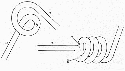
Fig. 16.—Making a spiral.
GROUND JOINTS
It is sometimes required to join two pieces of tubing
end to end, by means of a ground joint. Whenever
possible, a regular sealed joint should be used instead
of this ground joint, as it is quicker to make, and
more certain to be tight. Where a ground joint is
necessary, however, it is best made in the conical form
shown in c, Fig. 17. If the wall of the tube to be used[Pg 52]
is not very thick, it is thickened by collecting glass as
for a bulb on the ends of two tubes (Exercise No. 6), and
drawing to form cones of suitable shape (a and b, Fig. 17)
and of such relative sizes that a will slip about half way
into b. In order to make a straight and give it the proper
angle, it may be rolled when hot, upon a hot plate of carbon.
Blowing during this rolling is often helpful to
remove depressions. After b has been drawn to nearly
the proper size and shape, it may be smoothed by the use
of a small carbon rod, held inside it at a slight angle, or
better by the use of a truncated hexagonal pyramid of
carbon, whose edges have the proper slant to make the
inside of the cone right. The proper taper for both these
cones is the same as that used in stopcocks of similar size.
The hexagonal carbon can easily be made by carefully
filing down an electric light carbon, and finally impregnating
it with paraffin or beeswax, and is extremely useful
wherever a conical surface has to be formed from the
inside of a tube.
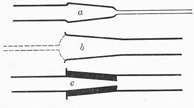
Fig. 17.—Ground joint.
The tail is allowed to remain on piece a, as a sort of
guide in grinding, and should therefore be in the axis of
the tube and have rather thick walls. Grind with emery
or carborundum, as described under a previous head.
(Regrinding plug for stopcock.) If many such joints are
to be made, it will pay to have a little sleeve of brass made
with the proper taper, and rough down the plug a in it
to about the proper size, while b is roughed down by
means of a brass or iron plug having the same taper.
This prevents excessive grinding of one-half of the joint
in order to remove a defect in the other half, and is the
method commercially used in making stopcocks.
SEALING IN PLATINUM WIRE
Very often it is necessary to seal platinum wire into
the wall of a tube. Professional glass-blowers usually[Pg 53]
use a special sort of glass (“Einschmelzglas”) which
is usually a lead glass, and is made of such composition
that it has the same or practically the same
coefficient of expansion as platinum. A little globule
of this glass is sealed into the tube in such a way that
it joins the platinum to the glass of the tube. To do
this, the small globule of special glass is fused on the
platinum wire at the proper point and the tube into
which the wire is to be sealed is heated and a small tail
drawn out at the point where the wire is to be inserted.
The lump of the special glass should be from 3⁄32 to
1⁄8 inch in diameter, and the tail drawn on the tube
should have a slightly less diameter at the point (about
1⁄8 inch or less from the tube) where it is cut off. There
are now two ways of sealing in the wire. (1) The wire
with the globule of glass is placed inside the tube and
the latter revolved until the end of the wire sticks out
of the cut tail (a, Fig. 18). The latter is now gently
heated, and the two glass surfaces fused together, taking
care to use only the end of the hissing flame, if the special
glass contains lead. (See Chapter I, page 1.) The
whole circumference of the tube is then heated and annealed
carefully. (2) The end of the wire which is to
be outside the tube is attached to the end of a thin scrap[Pg 54]
of glass, by heating the glass and thrusting the wire into
it a very little way. Using this piece of glass as a handle,
the wire is inserted in the cut tail (b, Fig. 18) and the
globule brought near to the end of the tail. (If the main
tube is cold, it must of course first be warmed.) With
the end of the hissing flame, as in the first method, the
globule of glass is melted and the end of the tail softened.
The wire is now pushed into place, the handle removed
by heating the end and withdrawing it, and the tail reheated
a little if necessary to make it shrink back into
line with the walls of the tube. The whole circumference
of the tube is heated at that point and annealed as
usual.
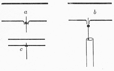
Fig. 18.
The use of this special glass is not absolutely necessary
if the platinum wire is small (1⁄4 millimeter or less in
diameter), and in fact it is often better in such cases
not to use it, unless the apparatus is to be subjected to
a very high vacuum. On small tubes, especially, it is
undesirable to use the special glass, as a lump of it will
usually cause the tube to crack on cooling. When such
glass is not at hand or is not to be used, the procedure
is altered somewhat. The tail which is drawn out is
very fine, having only a sufficient diameter so that when
it is cut off the wire can be inserted in it. Such a fine
tail is readily made by heating a small spot on the tube,
touching it with a warm platinum wire, removing from
the flame and drawing out the tail with the wire. After
cutting off the tail the wire is inserted in it, being held
on a scrap of glass as in the previous case, and the wire
and tail heated until the latter shrinks back into line
with the walls of the tube. If too great shrinkage occurs,
the place may be blown out gently after reheating.
Thus the wire is sealed through the wall of the tube without
changing the thickness of the latter, and consequently
without developing undue stresses at that point. Such[Pg 55]
a joint must of course be carefully reheated and annealed.
With fine platinum wire there is very little
risk of the tube cracking if care is taken to avoid formation
of any lump and to reheat the whole circumference
of the tube at that point.
Any glass adhering to the end of the platinum wire,
where the scrap of glass was sealed on for a handle, may
be removed when the glass has cooled by crushing it
carefully with a pair of pliers.
SEALING VACUUM TUBES
Tubes which have been evacuated usually are sealed
off while they are still connected to the vacuum pump.
The connection should be through a small, rather
thick-walled tube. When this is to be sealed, it is slowly
heated toward the softening point. As the glass just
begins to soften, the air-pressure will force it in, and
care must be taken that the softening is uniform over
the whole circumference of the tube. As the shrinking
goes on, the tube is gently drawn out to make a thick-walled
cone at that place, and the end is drawn off as
soon as the tube is sealed. The principal point to be
guarded is the thickness of the walls of the cone, and
uniform heating. A thin place or a hot place will give
way under the air-pressure and be sucked into the tube.
CLOSED TUBES FOR HEATING UNDER PRESSURE
(Carius method for determination of the halogens and
sulphur.) In this case the tubing used must have thick
walls (usually about 3⁄32 inch) to withstand the pressure.
Its external diameter is usually about 3⁄4 inch. One
length will usually make two tubes of standard length
for the cannon furnace. Especial care must be taken in
heating and cooling it on account of the thick walls. A[Pg 56]
length is gradually warmed in the center, finally heated
at that point until soft, drawn out, cut apart and annealed.
Taking one of the pieces, the cone is carefully
heated and shrunk, as in Exercise 4, until its walls are
as thick as those of the main tube. A flame with a little
tinge of yellow should be used for this operation to prevent
devitrification (page 2), as the thick glass shrinks
slowly. The tail is now drawn off and the whole end
heated and gently blown several times to make a rounded
end, like a test-tube, with walls as thick as those of the
main tube. This must be carefully annealed. It is
more important that the walls be thick than that the end
be nicely rounded: it may indeed be left somewhat
conical in shape.
At a point about two inches from the open end of the
tube, it is slowly warmed and finally heated to the
softening point. Grasping the open end with a pair of
crucible tongs, it is cautiously pulled out, a little at a
time, usually during rotation in the flame, to make a
constriction of moderate wall-thickness, but of sufficient
internal diameter to admit the tube containing the substance.
After annealing this, cooling and cleaning the
tube, the acid and salt are introduced (the former by
means of a long-stemmed funnel) and the tube is inclined
and rotated about its axis so that the acid wets
its surface about half way up from the bottom. The
substance is now weighed out in a piece of thin-walled
glass tubing, closed at one end, and about two inches long.
Inclining the large tube at a suitable angle, the small one
is introduced, closed end first, and allowed to slide down
the walls of the large tube until it reaches the place where
the acid has wet the tube. Here it will stop, and if the
tube is kept inclined during the rest of the operation it
will roll around inside the tube at this point and thus
not get down where any acid is likely to get into it and[Pg 57]
produce any pressure by decomposing it before the open
end of the tube is sealed. Now the tube is held in an
inclined position, taking care that the acid does not reach
up to the substance, the constricted portion cautiously
warmed and shrunk. It is finally shrunk and drawn out
into a somewhat elongated cone, with walls as thick as
the rest of the tube, and when this is accomplished the
end of the cone is sealed and the waste piece drawn off.
Anneal with great care, and cool in such a position that
the acid cannot reach the hot glass. The shrinking of
this cone takes a good deal of patience, and is one of the
most important parts of the process. If the walls are
left too thin, the tube may burst when heated, and the
whole labor is lost. If care is taken, the same tube can
be used for a number of determinations, until it becomes
quite short.
INDEX
Bellows, 4,
Bending glass, 8,
Blowing glass, 13, 19, 20, 21, 24, 29, 31,
with a rubber tube, 22,
Blowpipe, 4,
Bulb at end of tube, 28,
in middle of tube, 32,
very large, 32,
Bulbs, string of, 33,
Capillary tube, drawing on larger tube, 9, 54,
tubing, working, 43,
Carius method, tubes for, 55,
Closed circuits of tubing, 48,
tubes, for heating under pressure, 55,
Collecting glass for bulb, 29, 31, 32,
Constricting a tube, 10,
Crystallization of glass, see Devitrification.
Drawing out a tube, 9, 18, 19, 27,
Flanging a tube, 11, 14,
tool, 11,
Gas-washing tube, 35,
Glass, bending, 8,
blowing, 13, 19, 20, 21, 24, 29, 31,
collecting for bulb, 29, 31, 32,
cutting, 7,
defects, 2,
grinding, 47,
hard, 1,
knife, 7,
lead, 1,
qualities desired, 1,
rod and tube, joining, 45,
rod, working, 44,
shrinking, 18, 19, 22, 26,
soft, 1,
working temperature, 1, 13, 19, 27,
Grinding stopcock or joint, 47,
Ground joints, 51,
Handle on stopcock, mending, 45,
Hard glass, 1,
Insertion of tube through another, see Sealing a tube through another tube.
Joints, ground, 51,
Joining rod and tube, 45,
tubing end to end: first method, 16,
second method, 20,
Joining tubes of different diameters, 25,
a new tube to a stopcock, 48,
Kjeldahl trap, 41,
Lead glass, 1,
Lump of glass, removed, 18, 19, 20, 21, 24, 26, 30, 38,
Platinum wires, sealed into glass, 1, 52,
Position for glass-working, 5,
Pressure, tubes for heating under, 55,
Quality of glass, 1,
Rod, glass, working, 44,
Rubber tube used for blowing, 22,
Sealing a tube through another tube, 35, 39,
Sealing vacuum tubes, 55,
Shrinking glass, 18, 19, 22, 26, 31,
Soda glass, 1,
Soft glass, 1,
Spirals, making, 50,
Stopcocks, mending, 45,
Sulphur dioxide tube, 28,
“Tail” of glass, drawing out, 9, 54,
removed, 30, 35,
Tubes, closed, for heating under pressure, 55,
“Tee” tube, 22,
on capillary tubing, 43,
small side tube on a large tube, 24,
Vacuum tubes, sealing, 55,